Note: Descriptions are shown in the official language in which they were submitted.
CA 03150060 2022-02-04
WO 2021/026357 PCT/US2020/045210
BUNION CORRECTION SYSTEM AND METHOD
INCORPORATION BY REFERENCE TO ANY RELATED APPLICATIONS
[0001] The present application is related to U.S. Patent Application
No.
16/033,086, titled "BUNION CORRECTION SYSTEM AND METHOD." The entire
disclosure of which is hereby made part of this specification as if set forth
fully herein and
incorporated by reference for all purposes, for all that it contains. This
application claims the
benefit of U.S. Patent Application No. 62/883,819, titled "BUNION CORRECTION
SYSTEM AND METHOD," filed August 7, 2019, the entirety of which is hereby
incorporated by reference.
FIELD
[0002] The present invention relates to surgical treatment for
deformities of the
foot. More specifically, the present invention relates to implants,
instrumentation and
methods for minimally invasive bunion correction.
BACKGROUND
[0003] Bunions are a progressive disorder typically beginning with a
leaning of
the great toe, which may gradually change the angle of the bones and produce a
characteristic
bump on the medial side of the metatarsal near the joint of the metatarsal
with the proximal
phalanx. Specifically, the bunion is the prominence made of bone and at times
an inflamed
bursa. Hallux valgus is the condition in which the great toe deviates from the
normal position
toward the direction of the second toe.
[0004] Bunion correction or repair is a common surgery with over
100,000
surgeries performed annually in the US. Many surgical procedures for bunion
repair are
invasive and painful, requiring an incision of several inches and a long
period of
convalescence, of up to 10-12 weeks. Minimally invasive surgery has been
performed in
orthopedics for decades. However, creating the bone cuts has been performed
with burrs and
drill bits inserted blindly through small incisions. This method of surgery
lends itself to
potential adjacent soft tissue damage and unrepeatable results from patient to
patient. The
disclosure contained herein seeks to remedy this problem by providing an
instrumented
-1-
CA 03150060 2022-02-04
WO 2021/026357 PCT/US2020/045210
technique and guides to provide repeatability and limit the damage to tissue
along with a
simple implant insertion technique.
[0005] Disclosed herein is an implant and method for bunion repair
which can be
performed as a minimally invasive procedure, thus reducing discomfort,
scarring and
recovery time in comparison with more invasive bunion correction procedures.
SUMMARY OF THE INVENTION
[0006] The various systems and methods of the present invention have
been
developed in response to the present state of the art, and in particular, in
response to the
problems and needs in the art that have not yet been fully solved by currently
available
techniques. The systems and methods of the present invention may provide
techniques for
bunion correction which result in a streamlined procedure, faster recovery,
reduced scarring,
and reduced discomfort during healing.
[0007] To achieve the foregoing, and in accordance with the invention
as
embodied and broadly described herein, one aspect of the disclosure is a first
method for
correcting a bunion formed at the joint between a metatarsal and a great toe.
An incision is
made along a side of the metatarsal. A target location is selected on the
metatarsal. The
metatarsal is resected into a first metatarsal portion and a separate second
metatarsal portion
at the target location. The first metatarsal portion has a distal-facing
surface created by the
resecting. A pocket instrument is inserted into the first metatarsal portion
at the distal-facing
surface to create a pocket in the first metatarsal portion at the distal-
facing surface. An
implant is inserted through the incision into the pocket of the first
metatarsal portion, the
implant having a monolithic body with a head and an anchor.
[0008] In another aspect of the first method, the pocket extends into
an
intramedullary canal of the first metatarsal portion through the distal-facing
surface.
[0009] In another aspect of the first method, at least one k-wire
inserts into the
first metatarsal portion through the distal-facing surface. The first k-wire
guides the first
instrument into the first metatarsal portion to create the pocket.
[0010] In another aspect of the first method, the first pocket
instrument is a
broach.
-2-
CA 03150060 2022-02-04
WO 2021/026357 PCT/US2020/045210
[0011] In another aspect of the first method, the broach includes a
handle aligned
along a first axis, a insertion portion having a plurality of teeth aligned
along a second axis,
and an offset portion between the handle and the insertion portion such that
the first axis is
angled with respect to the second axis.
[0012] In another aspect of the first method, the implant head
attaches to the first
metatarsal portion.
[0013] In another aspect of the first method, the implant head
attached to the first
metatarsal portion includes inserting a screw through an aperture of the
implant head and into
the first metatarsal portion.
[0014] In another aspect of the first method, the implant head
attaches to the
second metatarsal portion.
[0015] In another aspect of the first method, a length of suture is
secured to the
great toe, tensioning the suture to re-align the great toe relative to the
first metatarsal portion,
and attaching the length of suture to the implant head.
[0016] In another aspect of the first method, the second metatarsal
portion
translates to expose the distal-facing surface on the first metatarsal
portion.
[0017] Another aspect of the disclosure is a second method for
correcting a
bunion. An incision is made along a side of the metatarsal. A target location
is selected on the
metatarsal. The metatarsal is resected into a first metatarsal portion and a
separate second
metatarsal portion, the first metatarsal portion having a distal-facing
surface created by the
resecting. An implant is implanted through the incision into the first
metatarsal portion. The
implant has a monolithic body having a head and an anchor, the anchor
extending along an
implant axis. The implant head is firstly attached to the first metatarsal
portion at the distal-
facing surface; and the implant head is secondly attached to the second
metatarsal portion.
[0018] In another aspect of the second method, the implant head is
attached to the
first metatarsal portion and includes inserting a first screw through a first
aperture of the
implant head and into the distal-facing surface of the first metatarsal
portion.
[0019] In another aspect of the second method, the first aperture is
aligned along a
first axis at a first angle relative to the implant axis.
-3-
CA 03150060 2022-02-04
WO 2021/026357 PCT/US2020/045210
[0020] In another aspect of the second method, the first angle is less
than
approximately 45 .
[0021] In another aspect of the second method, attaching the implant
head to the
second metatarsal portion includes inserting a second screw through a second
aperture of the
implant head and into the second metatarsal portion.
[0022] In another aspect of the second method, the second aperture is
aligned
along a second axis at a second angle relative to the implant axis, the second
angle being
greater than the first angle.
[0023] In another aspect of the second method, the second angle is
greater than
60 .
[0024] In another aspect of the second method, the second metatarsal
portion
translates to expose the distal-facing surface on the first metatarsal
portion. A pocket is
created in the first metatarsal portion at the distal-facing surface, and the
pocket extends into
an intramedullary canal of the first metatarsal portion through the distal-
facing surface.
[0025] In another aspect of the second method, a pocket instrument is
inserted
and guided by at least one k-wire into the first metatarsal portion at the
distal-facing surface
to create the pocket.
[0026] In another aspect of the second method, a length of suture is
secured to the
great toe, tensioning the suture to re-align the great toe relative to the
first metatarsal portion,
and attaching the length of suture to the implant.
[0027] Another aspect of the disclosure is a third method for
correcting a bunion.
An incision is made along a side of the metatarsal. A first k-wire is
introduced through the
incision and into the metatarsal at a selected target location. The metatarsal
is resected into a
first metatarsal portion and a separate second metatarsal portion at the
selected target
location. The first metatarsal portion has a distal-facing surface created by
the resecting. A
second k-wire is inserted into the first metatarsal portion at the distal-
facing surface. A pocket
instrument is inserted into the first metatarsal portion at the distal-facing
surface guided by
the second k-wire to create a pocket in the first metatarsal portion at the
distal-facing surface.
An implant is inserted through the incision into the first metatarsal portion,
the implant
having a monolithic body having a head and an anchor, the anchor extending
along an
-4-
CA 03150060 2022-02-04
WO 2021/026357 PCT/US2020/045210
implant axis. The implant head is attached to the first metatarsal portion at
the distal-facing
surface and attaching the implant head to the second metatarsal portion.
[0028] In another aspect of the third method, attaching the implant
head to the
first metatarsal portion includes inserting a first screw through a first
aperture of the implant
head and into the distal-facing surface of the first metatarsal portion and
attaching the implant
head to the second metatarsal portion includes inserting a second screw
through a second
aperture of the implant head and into the second metatarsal portion.
[0029] In another aspect of the third method, the second metatarsal
portion
translates to expose the distal-facing surface on the first metatarsal
portion; and a pocket is
created in the first metatarsal portion at the distal-facing surface, wherein
the pocket extends
into an intramedullary canal of the first metatarsal portion through the
distal-facing surface.
[0030] These and other features and advantages of the present
invention will
become more fully apparent from the following description and appended claims,
or may be
learned by the practice of the invention as set forth hereinafter.
BRIEF DESCRIPTION OF THE DRAWINGS
[0031] Exemplary embodiments of the invention will become more fully
apparent
from the following description and appended claims, taken in conjunction with
the
accompanying drawings. Understanding that these drawings depict only exemplary
embodiments and are, therefore, not to be considered limiting of the
invention's scope, the
exemplary embodiments of the invention will be described with additional
specificity and
detail through use of the accompanying drawings in which:
[0032] Figure 1A is a perspective view of a bunion correction implant,
comprising a nail and a fastener, according to one embodiment of the
invention; Figure 1B is
an exploded view of the implant;
[0033] Figure 2 is a perspective view of a partial skeleton of a foot,
with the
implant of Figure 1A implanted into the first metatarsal;
[0034] Figure 3A is medial view of the nail of Figure 1A; Figure 3B is
lateral
view of the nail of Figure 1A; Figure 3C is a superior view of the nail of
Figure 1A;
-5-
CA 03150060 2022-02-04
WO 2021/026357 PCT/US2020/045210
[0035] Figure 4 is a perspective view of the foot skeleton with a k-
wire inserted
into the metatarsal and a first guide mounted on the k-wire, the first guide
having a plurality
of guide holes;
[0036] Figure 5 is a perspective view of the foot skeleton, k-wire and
guide of
Figure 4, with additional k-wires inserted into the metatarsal;
[0037] Figure 6 is a perspective view of the foot skeleton, k-wires
and first guide
of Figure 5, with a trocar extending through one of the guide holes to create
a hole in the
metatarsal;
[0038] Figure 7 is a perspective view of the foot skeleton and k-wires
of Figure 5,
with a second guide mounted on the k-wires;
[0039] Figure 8 is a perspective view of the foot skeleton, k-wires
and second
guide of Figure 7, with a broach extending through a guide slot to cut an
osteotomy in the
metatarsal and separate the metatarsal into a proximal metatarsal portion and
a distal
metatarsal portion;
[0040] Figure 9 is a perspective view of the foot skeleton of Figure
8, with the
distal metatarsal portion shifted laterally relative to the proximal
metatarsal portion;
[0041] Figure 10 is a perspective view of the foot skeleton of Figure
9, with the
nail of Figure 1 mounted on an implant inserter and implanted into the
proximal metatarsal
portion;
[0042] Figure 11A is a medial view of the foot with the nail of Figure
1 implanted
in the proximal metatarsal portion and a needle and suture inserted into the
foot through an
incision at the site of the implant and exiting at a first location on the
great toe at the
proximal phalanx; Figure 11B is a medial view of the foot of Figure 11A, with
a first stitch
being made at the first location on the great toe; Figure 11C is a medial view
of the foot of
Figure 11B, with the needle emerging at a second location on the great toe;
Figure 11D is a
medial view of the foot of Figure 11C, with a second stitch being made at the
second location
on the great toe; Figure 11E is a medial view of the foot of Figure 11D, with
the suture routed
through an implant bore, and the needle and suture emerging through the
incision, and
showing a path of the suture;
-6-
CA 03150060 2022-02-04
WO 2021/026357 PCT/US2020/045210
[0043] Figure 12 is a perspective view of the foot skeleton of Figure
10 showing
the suture and the fastener aimed toward an opening of the nail;
[0044] Figure 13A is a perspective view of the first guide of Figure
5; Figure 13B
is a medial view of the first guide of Figure 5; Figure 13C is a lateral view
of the first guide
of Figure 5; Figure 13D is a superior view of the first guide of Figure 5;
Figure 13E is a distal
view of the distal end of the metatarsal, the first guide, and the trocar of
Figure 6 extending
through another one of the guide holes, with dotted lines indicating the
trajectories of the
plurality of guide holes;
[0045] Figure 14A is a medial perspective view of the second guide of
Figure 7;
Figure 14B is a medial view of the second guide of Figure 7; Figure 14C is a
side view of the
second guide of Figure 7; Figure 14D is a lateral perspective view of the
second guide of
Figure 7; Figure 14E is a medial view of another embodiment of a second guide;
[0046] Figure 15 is a perspective view of the broach of Figure 8;
[0047] Figure 16 is a perspective view of the implant inserter of
Figure 10;
[0048] Figure 17 is a perspective view of the foot skeleton of Figure
9, showing
the insertion of a k-wire into the proximal metatarsal portion;
[0049] Figure 18 is a perspective view of the foot skeleton of Figure
17, showing
a pocket instrument for forming a pocket inserted into the proximal metatarsal
portion as
guided by the k-wire;
[0050] Figure 19 is a side view of the pocket instrument shown in
Figure 18;
[0051] Figure 20 is a bottom view of the pocket instrument shown in
Figure 18;
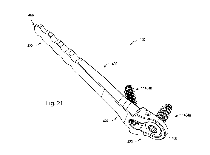
[0052] Figure 21 is a perspective view of another bunion correction
implant;
[0053] Figure 22 is an exploded view of the implant of Figure 21;
[0054] Figure 23 is a medial view of a nail of the implant of Figure
21;
[0055] Figure 24 is a lateral view of the nail of Figure 23;
[0056] Figure 25 is a section view of the implant of Figure 21;
[0057] Figure 26 is a medial view of a nail of another implant system;
[0058] Figure 27 is a lateral view of the nail of Figure 26;
[0059] Figure 28 is a superior view of the nail of Figure 26;
[0060] Figure 29 is a section view of the implant of Figure 26.
-7-
CA 03150060 2022-02-04
WO 2021/026357 PCT/US2020/045210
DETAILED DESCRIPTION
[0061] Exemplary embodiments of the invention will be best understood
by
reference to the drawings, wherein like parts are designated by like numerals
throughout. It
will be readily understood that the components of the invention, as generally
described and
illustrated in the Figures herein, could be arranged and designed in a wide
variety of different
configurations. Thus, the following more detailed description of the
embodiments of the
apparatus, system, and method, as represented in Figures 1A through 25, is not
intended to
limit the scope of the invention, as claimed, but is merely representative
exemplary of
exemplary embodiments of the invention.
[0062] The phrases "connected to," "coupled to" and "in communication
with"
refer to any form of interaction between two or more entities, including
mechanical,
electrical, magnetic, electromagnetic, fluid, and thermal interaction. Two
components may be
functionally coupled to each other even though they are not in direct contact
with each other.
The term "abutting" refers to items that are in direct physical contact with
each other,
although the items may not necessarily be attached together. The phrase "fluid
communication" refers to two features that are connected such that a fluid
within one feature
is able to pass into the other feature.
[0063] Directional and/or relational terms such as, but not limited
to, left, right,
superior, inferior, top, bottom, vertical, horizontal, medial, and lateral are
relative to each
other, are dependent on the specific orientation of an applicable element or
article, are used
accordingly to aid in the description of the various embodiments in this
specification and the
appended claims, and are not necessarily intended to be construed as limiting.
Standard
medical terminology may be used to describe human anatomy, or the relationship
of objects
to the human anatomy. For example, proximal refers to an object or anatomical
element
closer to the center of the body, while distal refers to an object or
anatomical element farther
away from the center of the body.
[0064] The word "exemplary" is used herein to mean "serving as an
example,
instance, or illustration." Any embodiment described herein as "exemplary" is
not necessarily
to be construed as preferred or advantageous over other embodiments. While the
various
-8-
CA 03150060 2022-02-04
WO 2021/026357 PCT/US2020/045210
aspects of the embodiments are presented in drawings, the drawings are not
necessarily
drawn to scale unless specifically indicated.
[0065] Referring to Figure 1A, a bunion correction implant system 100
according
to one embodiment of the invention includes a nail 102 and a fastener 104. As
seen in Figure
2, the nail 102 may be implanted to extend longitudinally into a proximal
portion 2a of a
resected metatarsal 2, and the fastener 104 inserted through a portion of the
nail to secure it to
the distal portion 2b of the metatarsal 2. The bunion correction implant
system 100 may
further include a suture which may be routed through the medial capsule of the
metatarsophalangeal (MTP) joint, secured in the soft tissues of the great toe,
tensioned to re-
align the position of the proximal phalanx 4 relative to the metatarsal, and
secured to the nail.
[0066] Referring to Figures 1A-B, and 3A-C, the implant nail 102 is a
monolithic
body extending from a first end 106 which may be a distal end, to a second end
108 which
may be a proximal end. The nail 102 may be generally rectangular in cross-
section, having a
medial side 110 which may be an outer side, a lateral side 112 which may be an
inner side, a
superior side 114, and an inferior side 116. The nail 102 includes a head 120,
an anchor 122,
and a neck 124 extending between the head 120 and the anchor 122.
[0067] With particular reference to Figures 3B and 3C, the nail anchor
122 and
neck 124 extend along a longitudinal axis 105, and the nail head 120 extends
distally away
from the neck 124 at an angle. The nail head extends between a head first end
126 and a head
second end 128 along a head first axis 107. In the embodiment depicted, the
angle a between
the head first axis 107 and the longitudinal axis 105 is 15 , with an angle 0
between the neck
lateral surface and the head lateral surface of 165 . In other embodiments of
the invention,
angle a may be in the range of 0 to 25 . In at least the embodiment depicted,
the nail 102
and assembled implant 100 are bilaterally symmetrical with respect to the
longitudinal axis
105, and with respect to the head first axis 107.
[0068] The nail head 120 includes an opening 130 centered on a head
second axis
109, which is perpendicular to the head first axis 107. The head second axis
may extend
generally medially-laterally (ML) upon implantation. In the embodiment
depicted, the
opening 130 extends between a head lateral side 115 and a head medial side
113, and
includes threads 132 for engagement with the fastener 104, although additional
embodiments
-9-
CA 03150060 2022-02-04
WO 2021/026357 PCT/US2020/045210
may lack threads. A concave lip 134 encircles the opening 130. The head second
end 128 is
wider than the neck 124 with respect to the superior-inferior dimension, and
includes a first
shoulder 140 and a second shoulder 142, the shoulders 140, 142 projecting
superiorly and
inferiorly, respectively, away from the neck 124 at the intersection of the
neck and the head.
The first shoulder 140 includes a first proximal shoulder surface 141, and the
second
shoulder 142 includes a second proximal shoulder surface 143. The proximal
shoulder
surfaces 141, 143 face proximally away from the head 120 and are at right
angles to the neck
superior and inferior sides 114, 116. The head 120 may further include a
transverse bore 148,
extending along a head third axis 111 which is perpendicular to the head first
axis 107 and
the head second axis 109. The head third axis 111 may extend generally
superiorly-inferiorly
(SI) upon implantation. In the embodiment depicted, the thickness of the head
120 between
its medial 113 and lateral 115 sides increases between the head first end 126
and the head
second end 128, so that the thickest part of the head is at the shoulders 140,
142.
[0069] The neck 124 extends between and connects the head 120 with the
anchor
122. The thickness of the neck 124 between the medial 110 and lateral 112
sides can vary
depending on the desired degree of shift of the metatarsal. In at least the
embodiment
depicted, the neck thickness tapers between the head 120 and the anchor
122.The width of the
neck 124 between the superior 114 and inferior 116 sides may also vary. The
length of the
nail between the first and second ends 106, 108 can vary, as can the relative
lengths of the
head, neck, and/or anchor portions. The anchor 122 is coaxial with the neck
124, and extends
from the neck to the second end 108 of the nail. Both the thickness of the
anchor between the
medial 110 and lateral 112 sides, and the width of the anchor between the
superior 114 and
inferior 116 sides may taper towards the nail second end, promoting easy
insertion of the nail
into bone. The anchor second end may be rounded as in the embodiment depicted
in Figures
1A and 1B; in other embodiments it may be pointed, flattened, serrated, or
another shape.
The anchor 122 includes a plurality of bone engagement features 144 which may
be shaped
as teeth, scallops, serrations, or other shapes to promote engagement within
bone. For
example, the scallops 146 in the embodiment depicted provide surface
irregularities which
resist nail backup. In the embodiment shown, the neck and anchor are free from
openings;
-10-
CA 03150060 2022-02-04
WO 2021/026357 PCT/US2020/045210
other embodiments could include openings for supplementary fixation or
instrument
connection.
[0070] Fastener 104 includes a fastener head 150, fastener shaft 152,
and tip 154.
The head 150 includes threads 156 for locking engagement with threads 132 in
the nail head
120; other embodiments may lack threads 156. The shaft 152 includes threads
158 for
engagement in bone. The head 150 may include a driving feature 157 for
engagement with a
driver. In the embodiment depicted, fastener 104 is a locking screw type
fastener; in other
embodiments the fastener may be locking or non-locking, and may be polyaxially
adjustable
or non-polyaxially adjustable.
[0071] The nail 102 and fastener 104 may comprise titanium, stainless
steel,
polyether ether ketone (PEEK), nitinol, and/or other rigid biocompatible
materials or
combinations thereof. The suture is a non-resorbable suture, although other
embodiments
may include a resorbable suture.
[0072] Referring to Figures 4-16, a method of correcting a bunion
includes one or
more of the following steps. Although the steps are described in an order, in
other
embodiments of the method one or more of the steps may be repeated, omitted,
or performed
in a different order.
[0073] A small incision is made in the affected metatarsal at the
medial side of
the bunion. Preferably, the incision is .5 inch long or less. Referring to
Figure 4, a first k-wire
159 is introduced through the incision and into the metatarsal at a selected
target location. A
first guide block 164 is mounted onto the k-wire 159 and urged toward the
metatarsal 2.
Referring to Figure 5, second and third k-wires 160, 162 are introduced
through the guide
block 164 into the metatarsal, on either side of the selected target location.
The second k-wire
160 is located in a proximal metatarsal portion 2a, and the third k-wire 162
is introduced into
a distal metatarsal portion 2b. The first k-wire 159 is removed from the
metatarsal.
[0074] As shown in Figures 13A-E, the first guide block 164 extends
between a
first or lateral side 166, and a second or medial side 168. First and second
guide portions 170,
172 project superiorly and inferiorly, respectively. A series of guide holes
174 extend through
the guide block, each defining a trajectory 175, which converge at a common
point, as seen in
Figure 13E. The guide holes 174 and their trajectories 175 are coplanar,
defining a cut plane
-11-
CA 03150060 2022-02-04
WO 2021/026357 PCT/US2020/045210
when the first guide block 164 is mounted on the k-wires 160, 162. A pair of
mounting holes
176, 178 are sized to slide over the k-wires. First and second mounting
supports 180, 182
extend medially from the guide block 164 and are separated by a gap 184. The
mounting
supports 180, 182 include slots 186, 188 for guiding and supporting the k-
wires, and prevent
rotation of the guide block 164 once mounted. The medial side 168 of the guide
block 164
may be convexly curved as shown.
[0075] Referring to Figures 6 and 13E, after the first guide block 164
is mounted
on the k-wires and abuts the metatarsal 2, a trocar 192, reamer or other
instrument is
introduced through one of the guide holes 174 and inserted into the metatarsal
2 to create a
hole through the metatarsal along the trajectory of the guide hole. The trocar
192 may then be
inserted through more of the guide holes 174 and through the metatarsal. This
step creates a
linear series of openings through the bone at the targeted location, weakening
the bone at that
location in preparation for a subsequent osteotomy to resect the metatarsal
head. After the
desired number of openings are created, the first guide block 164 is withdrawn
from the k-
wires .
[0076] Referring to Figure 7, a second guide block 200 is introduced
onto the k-
wires 160, 162. As shown in Figures 14A-D, the second guide block 200 extends
between a
first or lateral side 202, and a second or medial side 204. First and second
guide portions 206,
208 project superiorly and inferiorly, respectively. A cutting slot 210
extends through the
guide block 200, opening out on the lateral and medial sides 202, 204, and
mounting holes
212, 214 extend between the medial and lateral sides for mounting the block on
the k-wires.
The guide block 200 may be curved as shown, wherein the medial side 204 of the
guide block
200 is convexly curved and the lateral side 202 is concave. At least the
concave lateral
surface may allow the guide to fit closely against the targeted location. When
the second
guide block 200 is mounted on the k-wires 160, 162, the mid-plane of the
opening defined by
the cutting slot 210 is coplanar or at least parallel with the cut plane
defined by the first guide
block guide holes 174 and trajectories 175, and with the series of openings
created in the
bone in the previous step.
[0077] Figure 14E shows an alternative embodiment of a second guide
block
200a, similar to the second guide block 200 with the differences noted below.
The second
-12-
CA 03150060 2022-02-04
WO 2021/026357 PCT/US2020/045210
guide block 200a can extend between a first or medial side (204a) and a
lateral side (not
shown). The lateral side can be concave and the medial side 204a can be
convex. A cutting
slot 210a extends through the guide block 200a. The cutting slot 210a can
include a first
concave channel 210b on a first side of the cutting slot 210a and/or a second
concave channel
210c on a second side of the cutting slot 210a. The channels 210b, 210c can
form an aperture
for receiving a k-wire (e.g., first k-wire 159). First and second guide
portions 206a, 208a
project superiorly and inferiorly from the cutting slot 210a. Mounting holes
212a, 214a
extend between the medial and lateral sides. The second guide block 200a can
be mounted
first on a k-wire through the channels 210b, 210c and urged toward the
metatarsal 2 (See
Figure 4). Second and third k-wires 160, 162 can then be introduced through
the mounting
holes 212a, 214a and into the metatarsal 2. The first k-wire 159 can then be
removed from
the metatarsal 2.
[0078] Referring to Figures 8 and 15, a broach 220 is used to create
an osteotomy
in the metatarsal 2, resecting the metatarsal into the first or proximal
metatarsal portion 2a
and the second or distal metatarsal portion 2b. The broach 220 includes a
handle portion 222,
a shaft portion 224, and a insertion portion 226 with a cutting tip 228 and
cutting edges 230,
232. The cutting edges and tip may be beveled, sharpened, serrated and/or
otherwise
configured to cut through bone. The broach insertion portion 226 is urged
laterally through
the cutting slot 210 and into the bone to create the osteotomy. The shaft
portion 224 may act
as a stop to limit lateral insertion of the insertion portion through the
cutting slot. In other
embodiments of the method, instead of or in combination with broach 220, a
saw, blade,
chisel, osteotome, curette, pick, rasp or other instrument or combinations
thereof may be used
to perform the osteotomy. When the osteotomy step is completed, the second
guide block 200
is removed from the k-wires. Similarly, a cutting instrument, such as those
listed above, can
be urged laterally through the cutting slot 210a of the second guide block
200a and into the
bone to create the osteotomy.
[0079] Referring to Figure 9, the now separate distal metatarsal bone
portion 2b is
translated laterally relative to proximal metatarsal bone portion 2a. A
generally flat distal-
facing surface 2c on the proximal metatarsal portion 2a is exposed, and it is
into this surface
that the nail 102 is implanted. Distal-facing surface 2c of the proximal
metatarsal bone
-13-
CA 03150060 2022-02-04
WO 2021/026357 PCT/US2020/045210
portion 2a, and a medial-facing surface 2d of the distal metatarsal bone
portion 2b may be
referred to as abutment surfaces. The degree of offset of the distal
metatarsal portion may
vary but is sufficient to permit implantation of nail 102 into the distal-
facing surface 2c so
that the nail head 120 does not protrude medially beyond the medial outer
surface of the
proximal metatarsal portion 2a after implantation. The k-wires 160, 162 may be
removed
before or after the shifting of the distal metatarsal portion relative to
proximal metatarsal
portion.
[0080] Referring to Figures 10 and 16, the nail 102 is inserted
through the
incision and anchored into the prepared proximal metatarsal portion 2a. Prior
to implantation,
a suture 250 may be introduced to extend through the transverse bore 148. An
implant
inserter such as inserter 240 may be employed to implant the nail 102 into the
bone. Inserter
240 comprises a handle portion 242, a shaft portion 244, and an implant
engagement end 246.
Threads 248 are formed on the implant engagement end 246, which may cooperate
with the
nail threads 132 to removably attach the nail 102 to the inserter 240. The
inserter 240 is
moved to insert the anchor 122 and neck 124 proximally into the distal-facing
surface 2c and
into the intramedullary canal of the metatarsal, leaving the head 120 distal
to the proximal
metatarsal portion 2a. If needed, the inserter 240 may be tapped to drive the
nail 102 into
position in the proximal metatarsal portion 2a. The nail 102 is positioned so
that the proximal
surfaces 141, 143 of shoulders 140, 142 abut the prepared distal-facing
surface 2c of the
metatarsal, and the nail head lateral side 115 is immediately adjacent to
medial surface 2d of
the distal metatarsal portion 2b. When the nail 102 is properly seated in the
desired location,
the inserter 240 may be rotated to disengage it from the implanted nail 102.
[0081] Referring to Figures 11A-11F and 12, the suture 250 may be
engaged with
implant 100 and secured to soft tissues of the great toe 6 to change the
alignment of the
phalanx 4 relative to the metatarsal 2 and correcting hallux valgus. As shown
in Figure 11A,
a needle 260 carrying suture 250 is introduced through the incision 5, enters
the medial
capsule and emerges at a first location 6a on the epidermis of the great toe.
The suture
includes a first end 252 and a second end 254. As shown in Figure 11B, the
needle re-enters
the skin at location 6a, creating a first stitch 256 in the soft tissue
surrounding the phalanx 4.
Continuing to Figure 11C, the needle 260 and suture 250 emerge at a second
location 6b on
-14-
CA 03150060 2022-02-04
WO 2021/026357 PCT/US2020/045210
the epidermis of the great toe. Referring to Figure 11D, the needle 260 and
suture 250 re-
enter the great toe at location 6b, creating a second stitch 258 in the soft
tissue of the great toe
6. As shown in Figure 11E, the needle and suture second end 252 emerge through
the
incision 5. The suture 250 is tensioned to change the alignment of the phalanx
4 relative to
the metatarsal 2, providing tensile force along the medial side of the phalanx
and correcting
the hallux valgus. The nail shoulders 140, 142, abutting against the proximal
metatarsal
portion 2a act as a buttress to support the tension and alignment correction.
The tensioned
suture 250 is attached to the nail 102, with one or both of the first and
second ends 252, 254
passing through the transverse bore 148. The suture first end 252 may pass
through the
transverse bore 148 from the inferior side 116 to the superior side 114 of the
nail 102, and a
knot 262 may be tied at the superior side of the bore 148, maintaining the
suture tension and
the correction. The knot 262 may be wider than the diameter of the transverse
bore 148, so
that the knot cannot pass through the bore. After knotting, the remaining
suture free ends 252,
254 may be trimmed off. As seen in Figures 11E and 12, the suture 250 may
follow a three-
sided path from the implant 100 to the first and second stitches in the great
toe, and back to
the implant 100.
[0082] Referring to Figures 12 and 2, the screw tip 154 and shaft 152
are inserted
through the nail opening 130 to secure the nail head 120 to the distal
metatarsal portion 2b.
As the shaft threads 158 engage in the bone, the nail head 120 lateral side
115 is urged to
medial surface 2d of the distal metatarsal portion 2b. The screw head threads
156 engage
with the nail opening threads 132 to lock the screw 104 to the nail 102. The
incision 5 is
closed. Following closure of the incision, the suture 250 remains secured to
the great toe and
attached to the implant 100.
[0083] Figures 17-18 show an optional additional step in the insertion
process for
the bunion correction implant system 100 into a patient's foot, as shown and
described in
Figures 1-16 and the accompanying text. Figure 17 shows the separate distal
metatarsal
portion 2b and the proximal metatarsal portion 2a before the insertion of the
nail 102 into the
proximal metatarsal portion 2a. The distal metatarsal portion 2b can include
the medial facing
surface 2d. The proximal metatarsal portion 2a can include the distal facing
surface 2c. A k-
wire 360 can be inserted into the proximal metatarsal portion 2a. The k-wire
360 can be
-15-
CA 03150060 2022-02-04
WO 2021/026357 PCT/US2020/045210
inserted through the distal facing surface 2c. The k-wire 360 can include an
end 362. The end
362 can include a sharpened point. The end 362 can be inserted into the
intramedullary
portion of the metatarsal 2. The k-wire 360 can be inserted into the proximal
metatarsal
portion 2a after the distal metatarsal portion 2b is shifted relative to the
proximal metatarsal
portion 2a (e.g., to expose the distal facing surface 2c).
[0084] The k-wire 360 can be inserted at an angle corresponding to the
desired
positioning of the implant 100 within the proximal metatarsal portion 2a. The
entry point
and/or the angle of entry of the k-wire 360 into the distal facing surface 2c
can determine the
amount of offset between the distal metatarsal portion 2b and the proximal
metatarsal portion
2a. The k-wire 360 can accordingly be used to estimate the final positioning
of the distal
metatarsal portion 2b and the proximal metatarsal portion 2a. If the k-wire
360 is inserted in
an undesirable position, the k-wire can be easily removed and repositioned
within the
proximal metatarsal portion 2a. The k-wire 360 can be used as a guide for a
pocket
instrument 320. As shown in Figure 18, the pocket instrument 320 can be used
to remove
bone material from the proximal metatarsal portion 2a to form a pocket 380 for
the nail 102.
The nail 102 of the implant 100 can be inserted into the proximal metatarsal
portion 2a (e.g.,
into the pocket 380) using the steps and/or tools described above in Figure 10
and the
accompanying text. The nail head 120 can be aligned and attached with the
medially facing
surface 2d of the distal metatarsal portion 2b.
[0085] As shown further in Figures 19-20, the pocket instrument 320
can include
a handle 322. The pocket instrument 320 can include a insertion portion 326.
The handle 322
can be generally aligned along a first axis 323. The insertion portion 326 can
be generally
aligned along a second axis 327. In one implementation, the first and second
axes 323, 327
are parallel, although this is not required. The insertion portion 326 can be
connected at the
handle 322 by an offset neck 324. The offset neck 324 can space the handle
portion 322 apart
from the insertion portion 326.
[0086] The insertion portion 326 can be a broach, punch, or a non-
rotating cutting
instrument. The insertion portion 326 can include one or more cutting edges
330. The cutting
edges 330 can be used to remove material from the proximal metatarsal portion
2a to form
the pocket 380. Alternatively, the insertion portion 326 can be smoothed. The
insertion
-16-
CA 03150060 2022-02-04
WO 2021/026357 PCT/US2020/045210
portion 326 can include a tip 328. The insertion portion 326, whether smoothed
or including
the cutting edges 330, can be used to create a trial pocket for the nail 102.
The shape of the
pocket 380 can correspond to the shape of the nail 102 of the implant 100
(e.g., the insertion
portion 326). The insertion portion 326 can include a lateral side 312 and a
medial side 310.
The insertion portion 326 can include a superior side 314 and an inferior side
316. The
insertion portion 326 can be non-cylindrical in cross sectional shape (e.g.,
rectangular, as
shown). The non-cylindrical in cross sectional shape can enhance stability of
the nail 102
within the pocket 380. The pocket 380 (and/or the insertion portion 326) can
be smaller, in
one or more dimensions and/or along one or more sides, than the nail 102. The
nail 102 can
be in a press-fit condition within the pocket 380 (e.g., engaged with one or
more opposing
sides of the pocket 380) after insertion. In some implementations, the
aperture 380 and
insertion portion 326 can be sized to the dimensions of the nail 102.
[0087] The insertion portion 326 can include a channel 340. The
channel 340 can
extend along the second axis 327 of the insertion portion 326. The channel 340
can include a
proximate opening 342 and a distal opening 344. The proximal opening 342 can
be adjacent
to the offset neck portion 324. The distal opening 344 can be adjacent to the
tip 328.
[0088] In use to form the pocket 380, the insertion portion 326 of the
pocket
instrument 320 can be guided into the proximal metatarsal portion 2a along the
k-wire 360.
The offset neck 324 can space the handle portion 322 from the k-wire 360 to
improve the
ergonomics of the pocket instrument 320. The k-wire 360 can be received within
the channel
340. The pocket instrument 320 can be slid along a length of the k-wire 360
into the proximal
metatarsal bone portion 2a. The pocket instrument 320 can be moved in one or
more sawing
strokes or impacts (e.g., from a hammer striking the pocket instrument 320) to
form the
pocket 380. After forming the pocket 380, the k-wire 360 and the insertion
portion 326 can
be removed from the proximal metatarsal portion 2a. This implant system 100
can be
installed within the pocket 380, as described above.
[0089] Referring to Figures 21-25, a bunion correction implant system
400
according to another embodiment of the invention includes a nail 402, a first
fastener 404a,
and a second fastener 404b. The nail 402 may be implanted to extend
longitudinally into the
proximal metatarsal portion 2a of the resected metatarsal 2. The first
fastener 404a can be
-17-
CA 03150060 2022-02-04
WO 2021/026357 PCT/US2020/045210
inserted through a first portion of the nail 402 to secure it to the distal
metatarsal portion 2b
of the metatarsal 2. The second fastener 404b can be inserted through a second
portion of the
nail 402 to secure it to the proximal metatarsal portion 2a of the metatarsal
2. The implant
system 400 may further include a suture which may be routed through the medial
capsule of
the MTP joint, secured in the soft tissues of the great toe, tensioned to re-
align the position of
the proximal phalanx 4 relative to the metatarsal, and/or secured to the nail,
as described
above in relation to Figures 1-20 and the accompanying description.
[0090] The implant nail 402 can be a monolithic body extending from a
first end
406 which may be a distal end, to a second end 408 which may be a proximal
end. The nail
402 may be generally rectangular in cross-section. The nail 402 can have a
medial side 410
which may be an outer side, a lateral side 412 which may be an inner side, a
superior side
414, and/or an inferior side 416. The nail 402 can include a head 420. The
head 420 can be
one the first end 406. The nail 402 can include an anchor 422. The anchor 422
can be on the
second end 408. The nail 402 can include a neck 424. The neck 424 can extend
between the
head 420 and the anchor 422.
[0091] The nail anchor 422 and neck 424 can extend along an implant
axis 405.
The nail head 420 can extend distally away from the neck 424 at an angle a.
The nail head
420 can extend between a head first end 426 and a head second end 428 along a
head first
axis 407. The angle a between the neck lateral surface and the head lateral
surface can be
approximately 25 . In other implementations of the invention, angle a may be
in the range of
00 to 90 . Desirably, the angle a may be in the range of 0 to 60 . Desirably,
the angle a may
be in the range of 15 to 60 . In at least the embodiment depicted, the nail
402 and assembled
implant 400 are bilaterally symmetrical with respect to the implant axis 405,
and with respect
to the head first axis 407.
[0092] The nail head 420 includes a first opening 430a. The first
opening 430a
can be centered on the nail head 420. The first opening 430a can extend along
a head second
axis 410a. The head second axis 410a can be at an angle Al to the implant axis
405. The
angle Al can be between approximately 0 and 135 . Desirably, the angle Al may
be in the
range of 30 to 60 . The head second axis 410a may extend generally medially-
laterally (ML)
upon implantation. The first opening 430a can extend between a head lateral
side 415 and a
-18-
CA 03150060 2022-02-04
WO 2021/026357 PCT/US2020/045210
head medial side 413. The first opening 430a can include threads 432a for
engagement with
the first fastener 404a. Other implementations may lack threads. A concave lip
434a can
encircle the first opening 430. The head second axis 410a can be at an angle y
with the head
first axis 407. Angle y can be approximately 90 . Desirably, the angle y may
be in the range
of 45 to 135 .
[0093] The nail 402 can include a second opening 430b. The second
opening
430b can be on the nail head 420 and/or the neck 424. The second opening 430b
can be
centered on a head third axis 410b. The second opening 430b can extend between
the head
lateral side 415 and the head medial side 413. The head third axis 410b can be
at an angle A2
to the implant axis 405. The angle A2 can be less than approximately 45 .
Desirably, the
angle A2 may be in the range of 0 to 90 . Desirably, the angle A2 may be in
the range of 30
to 60 . The second opening 430b can include concave lip 434b. In some
implementations, the
second opening 430b can include threads (not shown) for engagement with the
second
fastener 404b.
[0094] The head second end 428 can be wider than the neck 424 with
respect to
the superior-inferior dimension. The head second end 428 can include a first
shoulder 440
and a second shoulder 442. The shoulders 440, 442 can project superiorly and
inferiorly,
respectively, away from the neck 424 at the intersection of the neck 424 and
the head 420.
The first shoulder 440 can include a first proximal shoulder surface 441. The
second shoulder
442 can include a second proximal shoulder surface 443. The proximal shoulder
surfaces
441, 443 can face proximally away from the head 420. The proximal shoulder
surfaces 441,
443 can be at right angles to the neck superior and inferior sides 414, 416.
[0095] The head 420 can include a transverse bore 448. The transverse
bore 448
can extend along a head fourth axis 411 which is perpendicular to the head
first axis 407 and
the head second axis 410a. The head fourth axis 411 can extend generally
superiorly-
inferiorly (SI) upon implantation. The thickness of the head 420 between the
medial 413 and
lateral 415 sides can increase between the head first end 426 and the head
second end 428 so
that the thickest part of the head 420 is at the shoulders 440, 442. A greater
thickness of the
head 420 between the medial 413 and lateral 415 sides can shift the head 420
further
-19-
CA 03150060 2022-02-04
WO 2021/026357 PCT/US2020/045210
outwardly with respect to a medial axis of the proximal metatarsal portion 2a.
The transverse
bore 448 can extend through the thickest part of the head 420.
[0096] The neck 424 can extend between and connect the head 420 with
the
anchor 422. The thickness of the neck 424 between the medial and lateral sides
410, 412 can
vary depending on the desired degree of shift of the metatarsal. The neck
thickness can taper
between the head 420 and the anchor 422. The width of the neck 424 between the
superior
414 and inferior 416 sides may also vary. The length of the nail 402 between
the first and
second ends 406, 408 can vary, as can the relative lengths of the head, neck,
and/or anchor
portions. The anchor 422 can be coaxial with the neck 424. The anchor 422 can
extend from
the neck 424 to the second end 408 of the nail 402. Both the thickness of the
anchor 422
between the medial and lateral sides 410, 412, and the width of the anchor 422
between the
superior 414 and inferior 416 sides can taper towards the nail second end 408.
This can
promote easy insertion of the nail 402 into metatarsal 2.
[0097] The anchor 422 at its second end 408 can be rounded, pointed,
flattened,
serrated, or another shape. The anchor 422 can include a plurality of bone
engagement
features 444 which may be shaped as teeth, scallops, serrations, or other
shapes to promote
engagement within bone. The neck 424 and anchor 422 can be free from or
include openings
for supplementary fixation or instrument connection.
[0098] Fastener 404a can include a fastener head 450a, driving feature
459a,
fastener shaft 452a, tip 454a, threads 456a for locking engagement with
threads in the nail
head 420 (e.g., opening 430a), and/or threads 458a for engagement in bone.
Fastener 404b
can include a fastener head 450b, driving feature 459b, fastener shaft 452b,
tip 454b and/or
threads 458b for engagement in bone. The fasteners 404a/404b can be locking
screw type
fasteners; in other implementations the fasteners 404a/404b can be locking or
non-locking,
and may be polyaxially adjustable or non-polyaxially adjustable. The nail 402
and fasteners
404a/404b may comprise titanium, stainless steel, PEEK, nitinol, and/or other
rigid
biocompatible materials or combinations thereof.
[0099] The implant system 400 can be used in place of the implant
system 100 in
the insertion process into a patient's foot as shown and described in Figures
1-20 and the
-20-
CA 03150060 2022-02-04
WO 2021/026357 PCT/US2020/045210
accompanying text. The implant system 400 can require the following further
steps to anchor
the nail 402 into the prepared proximal metatarsal portion 2a.
[0100] An implant inserter such as the inserter 240 may be employed to
implant
the nail 402 into the proximal metatarsal portion 2a. The implant engagement
end 246 can
cooperate with the openings 430a and/or 430b or otherwise with the nail 402.
The implant
engagement end 246 can include threads 248 that can engage with nail threads
432a (or nail
threads in the second opening 430b) to removably attach the nail 402 to the
inserter 240. The
inserter 240 is moved to insert the anchor 422 and neck 424 proximally into
the distal-facing
surface 2c and into the intramedullary canal of the metatarsal 2. Desirably,
the engagement
end 246 can cooperate with the opening 430b, which can more closely align the
inserter 240
with the anchor 422 and neck 424. Accordingly, the inserter 240 can be used to
apply force
more directly into the proximal metatarsal portion 2a as the anchor 422 and
neck are inserted.
[0101] The head 420 can be left distal to the proximal metatarsal
portion 2a. If
needed, the inserter 240 may be tapped to drive the nail 402 into position in
the proximal
metatarsal portion 2a. The nail 402 can be positioned so that the proximal
surfaces 441, 443
of shoulders 440, 442 abut the distal-facing surface 2c of the metatarsal. The
nail head lateral
side 415 can be immediately adjacent to medial surface 2d of the distal
metatarsal portion 2b.
With the nail 402 seated in the desired location, the inserter 240 can be
rotated to disengage it
from the implanted nail 402.
[0102] The fastener 404b can fasten the nail 402 with the proximal
metatarsal
portion 2a. A driver (e.g., screwdriver) can be employed to implant the
fastener 404b. The
driver can couple with the driving feature 459b. The tip 454b and shaft 452b
can be inserted
into the second opening 430b. The fastener 404b can be rotated to engage the
threads 458b
with the proximal metatarsal portion 2a. The installation of the fastener 404b
can
advantageously secure the position of the nail 402 relative to the metatarsal
2. Accordingly,
the suturing steps and alignment of the distal metatarsal portion 2b relative
to the nail 402 as
shown in Figures 11A-12 and described in the accompanying description can be
performed
more accurately.
[0103] Referring to Figures 26-29, a bunion correction implant system
500
according to another embodiment of the invention includes a nail 502. The
implant system
-21-
CA 03150060 2022-02-04
WO 2021/026357 PCT/US2020/045210
500 can be used in place of the implant system 400 in the insertion process
into a patient's
foot as shown and described above. The nail 502 may be implanted to extend
longitudinally
into the proximal metatarsal portion 2a of the resected metatarsal 2. The nail
502 can be fixed
with fasteners in the manner similar to the fasteners 404a, 404b described
above.
[0104] The implant nail 502 can be a monolithic body extending from a
first end
506 which may be a distal end, to a second end 508 which may be a proximal
end. The nail
502 can have a medial side 510 which may be an outer side, a lateral side 512
which may be
an inner side, a superior side 514, and/or an inferior side 516. The nail 502
can include a head
520. The head 520 can be one the first end 506. The nail 502 can include an
anchor 522. The
anchor 522 can be on the second end 508. The nail 502 can include a neck 524.
The neck 524
can extend between the head 520 and the anchor 522.
[0105] The nail anchor 522 and neck 524 can extend along an implant
axis 505.
The nail head 520 can extend distally away from the neck 524 at an angle al
along head axis
507. The angle al between the neck lateral surface (along axis 505) and the
head lateral
surface (along head axis 507) can be approximately 25 . In other
implementations of the
invention, angle al may be in the range of 0 to 90 . Desirably, the angle al
may be in the
range of 0 to 60 . Desirably, the angle al may be in the range of 15 to 60 .
In at least the
embodiment depicted, the nail 502 and assembled implant 500 are bilaterally
symmetrical
with respect to the implant axis 505.
[0106] The nail head 520 includes a first opening 530a and a second
opening
530b. The first and second head openings 530a, 530b can extend along
respective first and
second axes 510a, 510b. The first axis 510a can be at an angle B1 to the
implant axis 505.
The second axis 510b can be at an angle B2 to the implant axis 505. Angle B1
and B2 can be
equal, although this is not required. The angles Bl, B2 can be between
approximately 0 and
135 . Desirably, the angles Bl, B2 may be in the range of 30 to 90 . The axes
510a, 501b
may extend generally medially-laterally (ML) upon implantation. The first and
second
openings 530a, 530b can extend between a head lateral side and a head medial
side. The first
and second openings 530a, 530b can include threads 532a, 532b for engagement
with
fasteners. Other implementations may lack threads. A concave lip can encircle
the respective
-22-
CA 03150060 2022-02-04
WO 2021/026357 PCT/US2020/045210
first and second openings 530a, 530b. The first and/or second axes 510a, 510b
can be at
perpendicular to the axis 507.
[0107] The nail 502 can include a third opening 530c. The third
opening 530c can
be on the nail head 520 and/or the neck 522. The third opening 530c can be
centered on a
third axis 510c. The third opening 530c can extend between the head lateral
side and the head
medial side. The head third axis 510c can be at an angle B3 to the implant
axis 505. The
angle B3 can be less than approximately 45 . Desirably, the angle B3 may be in
the range of
0 to 90 . Desirably, the angle B3 may be in the range of 30 to 60 . The
third opening 530c
can include a concave or tapered up lip. In some implementations, the third
opening 530c can
include threads (not shown) for engagement with a fastener.
[0108] The neck 524 can extend between and connect the head 520 with
the
anchor 522. The neck 524 and/or anchor 522 may be generally rectangular in
cross-section.
The anchor 522 can extend from the neck 524 to the second end 508 of the nail
502. Both the
thickness of the anchor 522 between the medial and lateral sides 510, 512, and
the width of
the anchor 522 between the superior 514 and inferior 516 sides can taper
towards the nail
second end 508. This can promote easy insertion of the nail 502 into
metatarsal 2. The head
520 can include a transverse bore 548. The transverse bore 548 can extend
generally
superiorly-inferiorly (SI) upon implantation.
[0109] The anchor 522 at its second end 508 can be rounded, pointed,
flattened,
serrated, or another shape. The anchor 522 can include a plurality of bone
engagement
features 544 which may be shaped as teeth, scallops, serrations, or other
shapes to promote
engagement within bone. The neck 524 and anchor 522 can be free from or
include openings
for supplementary fixation or instrument connection.
[0110] Any methods disclosed herein comprise one or more steps or
actions for
performing the described method. The method steps and/or actions may be
interchanged with
one another. In other words, unless a specific order of steps or actions is
required for proper
operation of the embodiment, the order and/or use of specific steps and/or
actions may be
modified.
[0111] Reference throughout this specification to "an embodiment" or
"the
embodiment" means that a particular feature, structure or characteristic
described in
-23-
CA 03150060 2022-02-04
WO 2021/026357 PCT/US2020/045210
connection with that embodiment is included in at least one embodiment. Thus,
the quoted
phrases, or variations thereof, as recited throughout this specification are
not necessarily all
referring to the same embodiment.
[0112] Similarly, it should be appreciated that in the above
description of
embodiments, various features are sometimes grouped together in a single
embodiment,
Figure, or description thereof for the purpose of streamlining the disclosure.
This method of
disclosure, however, is not to be interpreted as reflecting an intention that
any claim require
more features than those expressly recited in that claim. Rather, as the
following claims
reflect, inventive aspects lie in a combination of fewer than all features of
any single
foregoing disclosed embodiment. Thus, the claims following this Detailed
Description are
hereby expressly incorporated into this Detailed Description, with each claim
standing on its
own as a separate embodiment. This disclosure includes all permutations of the
independent
claims with their dependent claims.
[0113] Recitation in the claims of the term "first" with respect to a
feature or
element does not necessarily imply the existence of a second or additional
such feature or
element. Elements recited in means-plus-function format are intended to be
construed in
accordance with 35 U.S.C. 112 Para. 6. It will be apparent to those having
skill in the art
that changes may be made to the details of the above-described embodiments
without
departing from the underlying principles of the invention.
[0114] While specific embodiments and applications of the present
invention
have been illustrated and described, it is to be understood that the invention
is not limited to
the precise configuration and components disclosed herein. Various
modifications, changes,
and variations which will be apparent to those skilled in the art may be made
in the
arrangement, operation, and details of the methods and systems of the present
invention
disclosed herein without departing from the spirit and scope of the invention.
[0115] The terms "approximately," "about," and "substantially" as used
herein
represent an amount close to the stated amount that still performs a desired
function or
achieves a desired result. For example, in some embodiments, as the context
may dictate, the
terms "approximately," "about," and "substantially," may refer to an amount
that is within
less than or equal to 10% of the stated amount. The term "generally" as used
herein
-24-
CA 03150060 2022-02-04
WO 2021/026357 PCT/US2020/045210
represents a value, amount, or characteristic that predominantly includes or
tends toward a
particular value, amount, or characteristic. As an example, in certain
embodiments, as the
context may dictate, the term "generally parallel" can refer to something that
departs from
exactly parallel by less than or equal to 20 degrees. Given ranges are
inclusive of endpoints.
-25-