Note: Descriptions are shown in the official language in which they were submitted.
INTEGRATED ELECTROMAGNET AND MAGLEV TRAIN
This application claims priority to Chinese Patent Application No.
202010211874.7,
titled "INTEGRATED ELECTROMAGNET AND MAGLEV TRAIN", filed on March 23,
2020 with the China National Intellectual Property Administration.
FIELD
The present disclosure relates to the technical field of maglev trains, and in
particular, to
an integrated electromagnet and a maglev train.
BACKGROUND
Currently, a high-speed maglev train in China has a maximum running speed of
503km/h, and higher guiding capability and braking capability are required
under high-speed
running. At present, the guiding function and emergency braking function of
the high-speed
.. maglev train are realized by a guiding electromagnet and a brake
electromagnet respectively.
In the conventional technology, two brake electromagnets and eight brake
controllers
are usually installed in each carriage. But the usage rate of this brake
system is extremely low.
The brake system is activated only when a serious failure occurs in the train.
However, even if
the brake system is not activated under normal operation of the train, it is
still equipped with a
power supply system, a controller and a brake electromagnet, which cause
serious waste of
resources, that is, a large amount of mechanical space is occupied, the weight
of the train is
increased, and the required capacity of the power supply system is also
increased. Therefore, it
is a problem to be solved by those skilled in the art to provide an integrated
electromagnet, to
solve the problem of resource waste of brake electromagnets.
SUMMARY
An objective of the present disclosure is to provide an integrated
electromagnet which
- -
Date Recue/Date Received 2023-07-12
can reduce the waste of brake electromagnet resources by combining the guiding
function and
the braking function together. Another objective of the present disclosure is
to provide a maglev
train which can reduce the waste of brake electromagnet resources by combining
the guiding
function and the braking function together.
To solve the above technical problems, an integrated electromagnet is provided
according to the present disclosure. The integrated electromagnet includes a
magnetic yoke and
magnetic poles in two rows that are located on a surface of the magnetic yoke
facing a guide
plate, the magnetic poles in one row correspond to the magnetic poles in the
other row one by
one, and an axis of a magnetic core in the magnetic pole is perpendicular to
the surface of the
magnetic yoke facing the guide plate;
where the magnetic poles include a first magnetic pole and a second magnetic
pole,
the first magnetic pole and the second magnetic pole in a row are arranged
alternately, the
first magnetic pole in any row is adjacent to the second magnetic pole in the
other row, the
first magnetic poles in a row are connected in series with each other and
connected to a
one-way output controller, and the second magnetic poles in a row are
connected in series
with each other and connected to a bidirectional output controller; and
where in a guiding state, the magnetic poles in a row have a same polarity,
and a
polarity of the magnetic poles in one row is opposite to a polarity of the
magnetic poles in
the other row; a current output by the bidirectional output controller in a
braking state has
a direction opposite to a current output by the bidirectional output
controller in the guiding
state.
Optionally, the first magnetic pole and the second magnetic pole in a row are
alternately
arranged one by one.
Optionally, the number of the magnetic poles in a row is an even number.
Optionally, a wear plate is provided on a surface of the magnetic poles facing
the guide
plate.
Optionally, the magnetic yoke is fixedly connected with three load-bearing
battens, the
three load-bearing battens are parallel to each other, and an axis of the load-
bearing batten is
- 2 -
Date Recue/Date Received 2023-07-12
parallel to an arrangement direction of the magnetic poles in a row.
Optionally, a back box is provided on a side of the magnetic yoke facing away
from the
guide plate, and the back box is fixedly connected to the load-bearing
battens.
Optionally, the integrated electromagnet further includes Y-direction
connection
subassemblies, and each Y-direction connection subassembly is simultaneously
fixedly
connected to surfaces of the three load-bearing battens facing away from the
guide plate.
Optionally, a cross section of the magnetic pole along a direction
perpendicular to the
axis of the magnetic core is in a rounded square shape, and the magnetic pole
includes the
magnetic core, a winding, an insulating layer, a short interface and a long
interface;
where the insulating layer covers a side wall of the insulating layer, and the
winding is
wound around the magnetic core along a surface of the insulating layer facing
away from the
magnetic core; the short interface is electrically connected to one port of
the winding, the long
interface is electrically connected to the other port of the winding, and both
the short interface
and the long interface extend to one end surface of the magnetic pole along
the axis of the
magnetic core.
Optionally, the cross section of the magnetic core along a direction
perpendicular to the
axis of the magnetic core is in a chamfered square shape, and the magnetic
pole further includes
an insulating support block; where the insulating support block is located at
four corners of the
magnetic core, and the insulating layer covers the magnetic core and the
insulating support
__ block.
A maglev train is provided according to the present disclosure, including any
one of the
above-mentioned integrated electromagnets.
The integrated electromagnet according to the present disclosure includes a
magnetic
yoke and magnetic poles in two rows that are located on a surface of the
magnetic yoke facing a
guide plate, the magnetic poles in one row correspond to the magnetic poles in
the other row
one by one, and an axis of a magnetic core in the magnetic pole is
perpendicular to the surface
of the magnetic yoke facing the guide plate. The magnetic poles include a
first magnetic pole
and a second magnetic pole, the first magnetic pole and the second magnetic
pole in a row are
- 3 -
Date Recue/Date Received 2023-07-12
arranged alternately, the first magnetic pole in any row is adjacent to the
second magnetic pole
in the other row, the first magnetic poles in a row are connected in series
with each other and
connected to a one-way output controller, and the second magnetic poles in a
row are connected
in series with each other and connected to a bidirectional output controller.
In a guiding state,
the magnetic poles in a row have a same polarity, and a polarity of the
magnetic poles in one
row is opposite to a polarity of the magnetic poles in the other row; a
current output by the
bidirectional output controller in a braking state has a direction opposite to
a current output by
the bidirectional output controller in the guiding state.
In the normal guiding state, a magnetic field is generated between adjacent
magnetic
poles in different rows due to their different polarities, thus a guiding
force with a direction
perpendicular to a forwarding direction of the train is generated between the
magnetic poles and
the guiding plate for guiding. When a braking operation is required, the
bidirectional output
controller outputs a reverse current, and in this case the polarity of the
second magnetic pole
will be reversed. Since the first magnetic pole in any row is adjacent to the
second magnetic
pole in the other row, and the first magnetic pole and the second magnetic
pole in a row are
alternately arranged, alternate polarities N and S along the forwarding
direction of the train are
formed, and a magnetic field is generated, thus a braking force for braking
the train is generated.
During the braking operation, polarities of adjacent magnetic poles in
different rows become
the same, thus no interference will occur. In this way, by integrating the
braking function and
the guiding function into one integrated electromagnet, resource waste of
brake electromagnets
can be greatly reduced.
A maglev train is provided according to the present disclosure, and the maglev
train also
has the above-mentioned beneficial effects, which will not be described
herein.
BRIEF DESCRIPTION OF THE DRAWINGS
In order to more clearly illustrate technical solutions in embodiments of the
present
disclosure or in the conventional technology, drawings used in the description
of the
embodiments or the conventional technology are introduced briefly hereinafter.
Apparently, the
drawings described in the following illustrate some embodiments of the present
disclosure, and
- 4 -
Date Recue/Date Received 2023-07-12
other drawings may be obtained by those ordinarily skilled in the art based on
these drawings
without any creative efforts.
Figure 1 is a schematic structural diagram of an integrated electromagnet
according to
an embodiment of the present disclosure;
Figure 2 is a cross-sectional view of Figure 1;
Figure 3 is a diagram of a power supply circuit in a guiding state according
to an
embodiment of the present disclosure;
Figure 4 is a of a power supply circuit in a braking state according to an
embodiment of
the present disclosure;
Figure 5 is a diagram of a magnetic path in a guiding state according to an
embodiment
of the present disclosure;
Figure 6 is a diagram of a magnetic path in a braking state according to an
embodiment
of the present disclosure;
Figure 7 is a principle diagram of power supply of a one-way output controller
according to an embodiment of the present disclosure;
Figure 8 is a principle diagram of power supply of a bidirectional output
controller
according to an embodiment of the present disclosure;
Figure 9 is a schematic structural diagram of an integrated electromagnet
according to
an embodiment of the present disclosure; and
Figure 10 is a schematic structural diagram of a magnetic pole according to an
embodiment of the present disclosure.
In the Figures:
1: Magnetic yoke; 2: First magnetic pole;
3: Second magnetic pole; 4: One-way output controller;
5: Bidirectional output controller; 6: Wear plate;
7: Load-bearing batten; 8: Back box;
- 5 -
Date Recue/Date Received 2023-07-12
9: Y-direction connection subassembly;
10: Gap sensor;
11: Guide plate; 21: Magnetic core;
22: Insulating layer; 23: Winding;
24: Short interface; 25: Long interface;
26: Insulating support block.
DETAILED DESCRIPTION
The present disclosure aims to provide an integrated electromagnet. In the
conventional
technology, two brake electromagnets and eight brake controllers are usually
installed in each
carriage. But the usage rate of this brake system is extremely low. The brake
system is activated
only when a serious failure occurs in the train. However, even if the brake
system is not
activated under normal operation of the train, it is still equipped with a
power supply system, a
controller and a brake electromagnet, which cause serious waste of resources,
that is, a large
amount of mechanical space is occupied, the weight of the train is increased,
and the required
capacity of the power supply system is also increased.
The integrated electromagnet according to the present disclosure includes a
magnetic
yoke and magnetic poles in two rows that are located on a surface of the
magnetic yoke facing a
guide plate, the magnetic poles in one row correspond to the magnetic poles in
the other row
one by one, and an axis of a magnetic core in the magnetic pole is
perpendicular to the surface
of the magnetic yoke facing the guide plate. The magnetic poles include a
first magnetic pole
and a second magnetic pole, the first magnetic pole and the second magnetic
pole in a row are
arranged alternately, the first magnetic pole in any row is adjacent to the
second magnetic pole
in the other row, the first magnetic poles in a row are connected in series
with each other and
connected to a one-way output controller, and the second magnetic poles in a
row are connected
in series with each other and connected to a bidirectional output controller.
In a guiding state,
the magnetic poles in a row have a same polarity, and a polarity of the
magnetic poles in one
- 6 -
Date Recue/Date Received 2023-07-12
row is opposite to a polarity of the magnetic poles in the other row; a
current output by the
bidirectional output controller in a braking state has a direction opposite to
a current output by
the bidirectional output controller in the guiding state.
In the normal guiding state, a magnetic field is generated between adjacent
magnetic
poles in different rows due to their different polarities, thus a guiding
force with a direction
perpendicular to a forwarding direction of the train is generated between the
magnetic poles and
the guiding plate for guiding. When a braking operation is required, the
bidirectional output
controller outputs a reverse current, and in this case the polarity of the
second magnetic pole
will be reversed. Since the first magnetic pole in any row is adjacent to the
second magnetic
pole in the other row, and the first magnetic pole and the second magnetic
pole in a row are
alternately arranged, alternate polarities N and S along the forwarding
direction of the train are
formed, and a magnetic field is generated, thus a braking force for braking
the train is generated.
During the braking operation, polarities of adjacent magnetic poles in
different rows become
the same, thus no interference will occur. In this way, by integrating the
braking function and
the guiding function into one integrated electromagnet, resource waste of
brake electromagnets
can be greatly reduced.
In order to make those skilled in the art understand the technical solutions
of the present
disclosure better, the technical solutions in the present disclosure are
described in detail below
in conjunction with the drawings and the embodiments of the present
disclosure. Apparently,
the described embodiments are only a part of the embodiments of the present
disclosure, rather
than all embodiments. Based on the embodiments in the present disclosure, all
of other
embodiments, made by the person skilled in the art without any creative
efforts, fall into the
scope of protection of the present disclosure.
Reference is made to Figures 1 to 8, in which Figure 1 is a schematic
structural diagram
of an integrated electromagnet according to an embodiment of the present
disclosure, Figure 2
is a cross-sectional view of Figure 1, Figure 3 is a diagram of a power supply
circuit in a
guiding state, Figure 4 is a diagram of a power supply circuit in a braking
state, Figure 5 is a
diagram of a magnetic path in a guiding state, Figure 6 is a diagram of a
magnetic path in a
braking state, Figure 7 is a principle diagram of power supply of a one-way
output controller,
- 7 -
Date Recue/Date Received 2023-07-12
and Figure 8 is a principle diagram of power supply of a bidirectional output
controller.
Reference is made to Figures 1 and 2, in an embodiment of the present
disclosure, an
integrated electromagnet includes a magnetic yoke 1 and magnetic poles in two
rows that are
located on a surface of the magnetic yoke 1 facing a guide plate 11, the
magnetic poles in one
row correspond to the magnetic poles in the other row one by one, and an axis
of a magnetic
core 21 in the magnetic pole is perpendicular to the surface of the magnetic
yoke 1 facing the
guide plate 11. The magnetic poles include a first magnetic pole 2 and a
second magnetic pole 3,
the first magnetic pole 2 and the second magnetic pole 3 in a row are arranged
alternately, the
first magnetic pole 2 in any row is adjacent to the second magnetic pole 3 in
the other row, the
first magnetic poles 2 in a row are connected in series with each other and
connected to a
one-way output controller 4, and the second magnetic poles 3 in a row are
connected in series
with each other and connected to a bidirectional output controller 5. In a
guiding state, magnetic
poles in a row have a same polarity, and a polarity of magnetic poles in one
row is opposite to a
polarity of magnetic poles in the other row; a current output by the
bidirectional output
controller 5 in a braking state has a direction opposite to a current output
by the bidirectional
output controller in the guiding state.
The magnetic yoke us made of a magnetic conductive material, thus the magnetic
yoke
1 can be magnetically permeable to form a magnetic path. In an embodiment of
the present
disclosure, the magnetic yoke 1 is usually made of steel of magnetic
conductive structure. The
material of the magnetic yoke 1 is not limited in the embodiment of the
present disclosure, as
long as it has good magnetic peimeability and enough mechanical strength,
depending on
specific situations.
The magnetic poles are located on the surface of the magnetic yoke 1 facing
the guide
plate 11, thus a magnetic attraction force generated between the magnetic
poles and the guide
plate 11 is transmitted to the magnetic yoke 1 first, and then to other
components through the
magnetic yoke 1. Correspondingly, in an embodiment of the present disclosure,
the magnetic
yoke 1 usually has a certain structural strength. A specific structure of the
magnetic pole will be
described in detail in following embodiments of the present disclosure, which
will not be
described here. In the embodiment of the present disclosure, the magnetic
poles are distributed
-8 -
Date Recue/Date Received 2023-07-12
in two rows, and the magnetic poles in one row correspond to the magnetic
poles in the other
row one by one. That is, the quantities of the magnetic poles in the two rows
are equal, and any
magnetic pole in one row is adjacent to a magnetic pole in the other row. hi
the embodiment of
the present disclosure, the axis of the magnetic core 21 in the magnetic pole
is perpendicular to
the surface of the magnetic yoke 1 facing the guide plate 11, thus a magnetic
field pointing
from the magnetic yoke 1 to the guide plate 11 is generated when the magnetic
poles operates.
Reference is made to Figures 3 and 4, the magnetic poles include a first
magnetic pole 2
and a second magnetic pole 3. It should be noted that in the embodiment of the
present
disclosure, structures of the first magnetic pole 2 and the second magnetic
pole 3 are generally
the same, and the difference is that the first magnetic pole 2 and the second
magnetic pole 3 are
connected to different types of controllers. The first magnetic pole 2 and the
second magnetic
pole 3 in a row are arranged alternately, and the first magnetic pole 2 in any
row is adjacent to
the second magnetic pole 3 in the other row. The first magnetic poles 2 in any
row are
connected in series with each other and connected to a one-way output
controller 4, and the
.. one-way output controller 4 outputs current in only one direction, that is,
the polarity of the first
magnetic poles 2 will not change in the embodiment of the present disclosure.
The second
magnetic poles 3 in any row are connected in series and are connected to a
bidirectional output
controller 5. The bidirectional output controller 5 outputs current from two
directions, that is,
the pole of the second electrodes may change in the embodiment of the
disclosure. Generally, in
the embodiment of the present disclosure, the integrated electromagnet is
connected to four
controllers, i.e., two one-way output controllers 4 and two bidirectional
output controllers 5.
Reference is made to Figures 5 and 6, in an embodiment of the present
disclosure, the
integrated electromagnet has a guiding state and a braking state during
operation. In the guiding
state, the polarities of magnetic poles in the same row are set to be the
same, and the polarities
of the magnetic poles in one row are opposite to the polarities of the
magnetic poles in the other
row, thus a magnetic field in a direction perpendicular to the axis of the
integrated
electromagnet is generated between the two rows of magnetic poles, that is, a
magnetic field in
a direction perpendicular to a moving direction of the integrated
electromagnet is generated.
The magnetic field passes through one magnetic pole in one row, an air gap
between the
- 9 -
Date Recue/Date Received 2023-07-12
magnetic pole and the guide plate 11, the guide plate 11, an air gap between
the guide plate 11
and the magnetic pole, the adjacent magnetic pole in the other row, the
magnetic yoke 1, and
then back to the magnetic pole in turn, to form a magnetic path. The magnetic
path generated
between different rows of magnetic poles will generate a magnetic attraction
force with the
guide plate 11, and a magnitude of the magnetic attraction force may be
changed by controlling
the magnetic field, thereby realizing the guiding function.
Reference is made to Figures 7 and 8, in the embodiment of the present
disclosure, a
direction of a current output by the bidirectional output controller 5 in the
braking state is
opposite to a direction of a current output in the guiding state. When the -
vain needs to stop
urgently, that is, when it needs to be in the braking state, the bidirectional
output controller 5
will output a reverse current compared to that in the guiding state, and thus
the polarity of the
second magnetic poles 3 will also be reversed. At this time, since the first
magnetic poles 2 and
the second magnetic poles 3 in the same row are alternately arranged,
alternated polarities N
and S of the magnetic poles in the same row are formed. Further, since the
first magnetic pole 2
in any row is adjacent to the second magnetic pole 3 in the other row, and the
polarities of the
adjacent magnetic poles in different rows are opposite in the guiding state,
in this case the
polarities of the adjacent magnetic poles in different rows are the same in
the braking state, thus
a magnetic field propagating in the direction of the magnetic pole arrangement
is formed.
Therefore in the braking state, the magnetic field passes through one magnetic
pole, an air gap
between the magnetic pole and the guide plate 11, the guide plate 11, an air
gap between the
guide plate 11 and an adjacent magnetic pole in the same row, the adjacent
magnetic pole, the
magnetic yoke 1, and back to the original magnetic pole in turn, to form a
magnetic path. Since
the polarities N and S of the two rows of magnetic poles alternates in the
running direction of
the train, an eddy current is generated in the guide plate 11 when the train
is running due to the
magnetic field alternating, thus an air gap magnetic flux between the two rows
of magnetic
poles and the guide plate 11 lags, that is, the magnetic field is tilted to a
certain extent. A
component of the tilted magnetic field in the running direction produces a
braking force to
realize a braking function, which is also known as eddy current braking
function, to achieve
braking.
- io -
Date Recue/Date Received 2023-07-12
Generally, the first magnetic pole 2 and the second magnetic pole 3 in the
same row are
alternately arranged one by one, to form a more dense magnetic field between
the first magnetic
pole 2 and the second magnetic pole 3 in the braking state, and the magnetic
field formed
between the first magnetic pole 2 and the second magnetic pole 3 will generate
a braking force
with the guide plate 11, that is, by alternately arranging the first magnetic
pole 2 and the second
magnetic pole 3 in the same row one by one, a stronger braking force can be
generated.
In the embodiment of the present disclosure, the quantity of the magnetic
poles in the
same row is usually an even number, and the quantity of the first magnetic
poles 2 and the
quantity of the second magnetic poles 3 in the same row are usually equal. In
the embodiment
of the present disclosure, the quantity of the magnetic poles in each row is
eight, and a total of
sixteen magnetic poles are provided. Alternatively, there may be other
quantity of magnetic
poles, which is not limited in the embodiment of the present disclosure.
The integrated electromagnet in the embodiment of the present disclosure
includes a
magnetic yoke 1 and magnetic poles in two rows that are located on a surface
of the magnetic
yoke 1 facing a guide plate 11, the magnetic poles in one row correspond to
the magnetic poles
in the other row one by one, and an axis of a magnetic core 21 in the magnetic
pole is
perpendicular to the surface of the magnetic yoke 1 facing the guide plate 11.
The magnetic
poles include a first magnetic pole 2 and a second magnetic pole 3, the first
magnetic pole 2 and
the second magnetic pole 3 in a row are arranged alternately, the first
magnetic pole 2 in any
row is adjacent to the second magnetic pole 3 in the other row, the first
magnetic poles 2 in a
row are connected in series with each other and connected to a one-way output
controller 4, and
the second magnetic poles 3 in a row are connected in series with each other
and connected to a
bidirectional output controller 5. In a guiding state, magnetic poles in a row
have a same
polarity, and a polarity of magnetic poles in one row is opposite to a
polarity of magnetic poles
in the other row; a current output by the bidirectional output controller 5 in
a braking state has a
direction opposite to a current output by the bidirectional output controller
in the guiding state.
In the normal guiding state, a magnetic field is generated between adjacent
magnetic
poles in different rows due to their different polarities, thus a guiding
force with a direction
perpendicular to a forwarding direction of the train is generated between the
magnetic poles and
- 11 -
Date Recue/Date Received 2023-07-12
the guiding plate 11 for guiding. When a braking operation is required, the
bidirectional output
controller 5 outputs a reverse current, and in this case the polarity of the
second magnetic pole 3
will be reversed. Since the first magnetic pole 2 in any row is adjacent to
the second magnetic
pole 3 in the other row, and the first magnetic pole 2 and the second magnetic
pole 3 in a row
are alternately arranged, alternate polarities N and S along the forwarding
direction of the train
are formed, and a magnetic field is generated, thus a braking force for
braking the train is
generated. During the braking operation, polarities of adjacent magnetic poles
in different rows
become the same, thus no interference will occur. In this way, by integrating
the braking
function and the guiding function into one integrated electromagnet, resource
waste of brake
electromagnets can be greatly reduced.
A specific structure of the integrated electromagnet according to the
embodiment of the
present disclosure will be described in detail in the following embodiments.
Reference is made to Figure 9, which is a schematic structural diagram of an
integrated
electromagnet according to an embodiment of the present disclosure.
Different from the above-mentioned embodiments of the present disclosure, a
specific
structure of the integrated electromagnet is introduced in this embodiment of
the present
disclosure on the basis of the above-mentioned embodiments of the present
disclosure. Other
contents regarding the integrated electromagnet have been introduced in detail
in the
above-mentioned embodiments, which will not be described again herein.
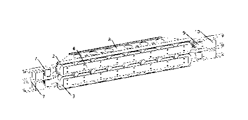
Referring to Figure 9, in this embodiment, a wear plate 6 is provided on a
side surface
of the magnetic poles facing the guide plate 11. The wear plate 6 is usually
riveted to the side
surface of the magnetic poles facing the guide plate 11 by a rivet. A material
of the wear plate 6
is usually tin bronze, which protects the magnetic poles and avoids the
magnetic poles from
being damaged due to mechanical contact between the electromagnet and the
guide plate 11
under special circumstances. The thickness of the wear plate 6 is usually not
more than 6 mm. It
should be noted that other materials may also be used as the material of the
wear plate 6, as
long as it can protect the magnetic poles from mechanical collision damage. It
should be noted
that the wear plate 6 is usually made of a non-magnetic material, to avoid
that the magnetic
field generated by the magnetic poles does not pass through the air gap and
thus not act on the
- 12 -
Date Recue/Date Received 2023-07-12
guide plate 11. The magnetic poles are divided into two rows. Correspondingly,
the wear plate 6
may be one piece that is arranged on the surface of the two rows of magnetic
poles facing the
guide plate 11; or, the wear plate 6 may also be divided into two pieces, and
each wear plate 6 is
arranged separately on a side surface of one row of magnetic poles facing the
guide plate 11.
Alternatively, the wear plate 6 may be in other shapes, and the specific shape
of the wear plate 6
is not specifically limited in the embodiment of the present disclosure.
In the embodiment of the present disclosure, the magnetic yoke 1 is fixedly
connected
with three load-bearing battens 7, the three load-bearing battens 7 are
parallel to each other, and
an axis of the load-bearing batten 7 is parallel to an arrangement direction
of the magnetic poles
.. in a row. Generally, the load-bearing battens 7 include an upper load-
bearing batten, a middle
load-bearing batten and a lower load-bearing batten. The upper load-bearing
batten and the
lower load-bearing batten are usually arranged on an upper side and a lower
side of the
magnetic yoke 1, and the middle load-bearing batten is usually arranged on a
surface of the
magnetic yoke 1 facing away from the guide plate 11 along the axis of the
magnetic yoke 1.
The three load-bearing battens 7 are fixedly connected to the magnetic yoke 1,
and are usually
fixed to the magnetic yoke 1 by a bolt. The load-bearing battens 7 are mainly
used for
load-bearing in the embodiment of the present disclosure. A magnetic force
between the
magnetic poles and the guide plate 11 will be transmitted to the load-bearing
battens 7 via the
magnetic yoke 1. In the embodiment of the present disclosure, the load-bearing
battens 7 only
play the role of force transmission, support and installation. The load-
bearing battens 7 are
compatible with an arm structure of the existing maglev train, and can
transmit the force
generated by the magnetic poles to the train.
In the embodiment of the present disclosure, the integrated electromagnet
further
includes a Y-direction connection subassembly 9, and each Y-direction
connection subassembly
9 is fixedly connected to surfaces of the three load-bearing battens 7 facing
away from the
guide plate 11. Generally, an integrated electromagnet is provided with two Y-
direction
connection subassemblies 9 which are respectively located at two ends of the
integrated
electromagnet. In order to ensure that more force generated by the magnetic
poles can be
transmitted to the train, each Y-direction connection subassembly 9 spans the
three load-bearing
- 13 -
Date Recue/Date Received 2023-07-12
battens 7, and is fixedly connected to the surfaces of the three load-bearing
battens 7 facing
away from the guide plate 11. In the embodiment of the present disclosure, the
integrated
electromagnet is connected to the train through the Y-direction connection
subassembly 9, and
the force generated between the magnetic poles and the guide plate 11 is
transmitted to the train
through the Y-direction connection subassembly 9.
In the embodiment of the present disclosure, a back box 8 is provided on a
side of the
magnetic yoke 1 facing away from the guide plate 11, and the back box 8 is
fixedly connected
to the load-bearing battens 7. The back box 8 is arranged on the side of the
magnetic yoke 1
facing away from the guide plate 11, and is mainly used for accommodating
components such
as wires connected to the electromagnet. Specifically, the back box 8 usually
includes an upper
cover plate, a lower cover plate, a middle cover plate and a rear cover plate.
The upper cover
plate is usually fixedly connected to the upper load-bearing batten by a bolt.
The middle cover
plate is usually fixedly connected to the middle load-bearing batten by a
bolt. The lower cover
plate is usually fixedly connected to the middle load-bearing batten by a
bolt. And the rear
cover plate is usually riveted to the upper cover plate, the lower cover plate
and the middle
cover plate by rivets, to form the back box 8. The back box 8 can increase the
strength of the
integrated electromagnet, and avoid great deformation of the integrated
electromagnet under the
action of the guiding force and braking force. Furthermore, the back box 8,
serving as an
installation carrier for connection cables of the magnetic poles, can protect
the cables from
being damaged. A power supply cable connector (not shown in the figure) is
usually fixed to the
upper cover plate and the lower cover plate of the back box 8. The material of
the upper cover
plate, lower cover plate, middle cover plate and rear cover plate is usually
aluminum alloy.
However the material of the back box 8 is not limited in the embodiment of the
present
disclosure, which depends on specific situations. Preferably, the material of
the back box 8 is a
non-magnetic material with low weight and high strength.
In the embodiment of the present disclosure, the integrated electromagnet is
usually
provided with four gap sensors 10 between the load-bearing battens 7. The gap
sensor 10 is
usually fixed between adjacent load-bearing battens 7 by a bolt, and is fixed
to the load-bearing
battens 7. The gap sensors 10 are mainly used for detecting a gap between the
integrated
- 14 -
Date Recue/Date Received 2023-07-12
electromagnet and the guide plate 11, which is functioned as a feedback of a
closed-loop
control system. A detection surface of the gap sensors 10 generally are 4 mm
to 6 mm lower
than a surface of the wear plate 6, to avoid damage to the gap sensors 10 when
the integrated
electromagnet is in contact with the guide plate 11.
According to the integrated electromagnet provided by the embodiment of the
present
disclosure, damage to the magnetic poles due to mechanical contact between the
electromagnet
and the guide plate 11 under special circumstances can be avoided by providing
the wear plate
6. In addition, by providing the back box 8, the strength of the integrated
electromagnet is
increased, and great deformation of the integrated electromagnet under the
action of the guiding
force and braking force is avoided. Furthermore, the back box 8, serving as an
installation
carrier for connection cables of the magnetic poles, can protect the cables
from being damaged.
A specific structure of the integrated electromagnet according to an
embodiment of the
present disclosure will be described in detail in the following embodiments.
Reference is made to Figure 10, which is a schematic structural diagram of a
magnetic
pole according to an embodiment of the present disclosure.
Different from the above-mentioned embodiments of the present disclosure, a
specific
structure of a magnetic pole in the integrated electromagnet is introduced in
this embodiment of
the present disclosure on the basis of the above-mentioned embodiments of the
present
disclosure. Other contents regarding the integrated electromagnet have been
introduced in detail
in the above-mentioned embodiments, which will not be described again herein.
Referring to Figure 10, in the embodiment of the present disclosure, a cross
section of
the magnetic pole along a direction perpendicular to the axis of the magnetic
core 21 is in a
rounded square shape, and the magnetic pole includes a magnetic core 21, a
winding 23, an
insulating layer 22, a short interface 24 and a long interface 25. The
insulating layer 22 covers a
side wall of the insulating layer 22, and the winding 23 is wound around the
magnetic core 21
along a surface of the insulating layer 22 facing away from the magnetic core
21; the short
interface 24 is electrically connected to one port of the winding 23, the long
interface 25 is
electrically connected to the other port of the winding 23, and both the short
interface 24 and
- 15 -
Date Recue/Date Received 2023-07-12
the long interface 25 extend to one end surface of the magnetic pole along the
axis of the
magnetic core 21.
The axis of the magnetic core 21 is perpendicular to the surface of the
magnetic yoke 1
facing the guide plate 11, and the winding 23 is wound around the axis of the
magnetic core 21
and therefore wound around on the surface of the magnetic core 21. In the
embodiment of the
present disclosure, the cross section of the magnetic pole in the direction
perpendicular to the
axis of the magnetic core 21 is in the rounded square shape, thus the length
and width of the
magnetic pole are substantially equal. The insulating layer 22 covers the side
wall of the
magnetic core 21, and the insulating layer 22 is mainly used for preventing a
short circuit
between the winding 23 and the magnetic core 21 from damaging the magnetic
pole. The
winding 23 is wound around the magnetic core 21 along the surface of the
insulating layer 22
facing away from the magnetic core 21, to form the magnetic pole. A specific
winding direction
of the winding 23 is not specifically limited in the embodiment of the present
disclosure, which
depends on specific situations. The winding 23 has two ports for electrical
connection with
.. other components. In the embodiment of the present disclosure, one port is
usually welded to
the short interface 24 to achieve electrical connection, and the other port is
welded to the long
interface 25 to achieve electrical connection. Both the long interface 25 and
the short interface
24 extend to one end of the magnetic pole along the direction of the axis of
the magnetic pole
on the surface of the winding 23, such that the long interface 25 and the
short interface 24 can
extend to the back box 8 to connect with wires in the back box 8 when the
magnetic pole is
installed in the integrated electromagnet according to the above-mentioned
embodiments of the
present disclosure.
In an embodiment of the present disclosure, a cross section of the magnetic
core 21 in
the direction perpendicular to the axis of the magnetic core 21 is in a
chamfered square shape,
and the magnetic pole further includes an insulating support block 26. The
insulating support
block 26 is located at four corners of the magnetic core 21, and the
insulating layer 22 covers
the magnetic core 21 and the insulating support block 26. The cross section of
the magnetic
core 21 in the direction perpendicular to the axis of the magnetic core 21 is
in the chamfered
square shape. To facilitate the arrangement of the insulating layer 22, the
insulating support
- 16 -
Date Recue/Date Received 2023-07-12
block 26 is provided at four corners of the magnetic core 21, and the shape of
the insulating
support block 26 corresponds to the shape of the magnetic core 21, to support
the insulating
layer 22. Correspondingly, the insulating layer 22 covers the magnetic core 21
and the
insulating support block 26.
Specifically, in an embodiment of the present disclosure, the winding 23 is
usually in a
double-layer structure. The double-layer winding 23 is beneficial to increase
the filling rate of
the winding 23, thereby improving the guiding and braking ability, and
reducing the heating of
the winding 23 as well. The winding 23 is usually composed of two materials
distributed
alternately, one layer of which is usually aluminum foil, and the other layer
is usually an
insulating film. The specific structure and material of the winding 23 are not
specifically limited
in the embodiment of the present disclosure, which depend on specific
situations. In an
embodiment of the present disclosure, epoxy resin is usually poured on the
surface of the
magnetic pole, and the epoxy resin can protect the internal structure of the
magnetic pole and
prevent the magnetic pole from being damaged by a short circuit due to
moisture.
A maglev train is also provided according to an embodiment of the present
disclosure.
The maglev train is specifically provided with the integrated electromagnet
according to any of
the above-mentioned embodiments. Details of the integrated electromagnet may
refer to the
above-mentioned embodiments of the present disclosure, and other structures of
the maglev
train may refer to the prior art, which will not be described again herein.
In the maglev train according to the embodiment of the present disclosure, the
braking
function and the guiding function are integrated in one integrated
electromagnet, thus the
electromagnet can share one set of control system and power supply system,
therefore greatly
reducing waste of brake electromagnet resources.
The above embodiments in the specification are described in a progressive
manner.
Each of the embodiments is mainly focused on describing its differences from
other
embodiments, and references may be made among these embodiments with respect
to the same
or similar portions among these embodiments.
The person skilled in the art can further appreciate that the elements and
algorithm steps
- 17 -
Date Recue/Date Received 2023-07-12
of each embodiment described in connection with the embodiments disclosed
herein can be
implemented in electronic hardware, computer software or a combination of
both, in order to
clearly illustrate the interchangeability of the hardware and software, the
composition and steps
of the various examples have been generally described in terms of function in
the above
description. Whether these functions are performed in hardware or software
depends on the
specific application and design constraints of the technical solution. The
person skilled in the art
can use different methods for implementing the described functions for each
particular
application; such implementation should not be considered to be beyond the
scope of the
present disclosure.
The steps of the method or algorithm described according to the embodiments
disclosed
herein can be implemented in forms of hardware, a software module executed by
a processor or
the combination of the both. The software module may be stored in a Random
Access Memory
(RAM), a memory, a Read-Only Memory (ROM), an electrically programmable ROM,
an
electrically erasable programmable ROM, a register, a hardware disk, a movable
magnetic disk,
CD-ROM or any other forms of storage medium well known in the art.
It should be further noted that, the relationship terminologies such as
"first", "second"
and the like are only used herein to distinguish one entity or operation from
another, rather than
to necessitate or imply that the actual relationship or order exists between
the entities or
operations. Further, the term "include", "comprise" or any variant thereof is
intended to
encompass nonexclusive inclusion so that a process, method, article or device
including a series
of elements includes not only those elements but also other elements which
have not been listed
definitely or an element(s) inherent to the process, method, article or
device. Moreover, the
expression "comprising a(n)
................................................... "in which an element is
defined will not preclude presence of
an additional identical element(s) in a process, method, article or device
comprising the defined
element(s) unless further defined.
The integrated electromagnet and the maglev train according to embodiments of
the
present disclosure are introduced in detail above. The principles and
embodiments of present
disclosure are described by specific embodiments in the specification. The
above description for
embodiments is only for helping to understand the method and key idea of the
present
- 18 -
Date Recue/Date Received 2023-07-12
disclosure. It should be pointed out that for the person skilled in the art,
several improvements
and modifications can be made to the present disclosure without departing from
the principle of
the present disclosure, and these improvements and modifications also fall
within the protection
scope covered by the claims of the present disclosure.
- 19 -
Date Recue/Date Received 2023-07-12