Note: Descriptions are shown in the official language in which they were submitted.
WO 2021/050212
PCT/US2020/046672
WATER PUMP FOR WATERCRAFT
BACKGROUND
Field
[0001] This application relates to a water
jet pump system for use on a watercraft.
Description
100021 Personal watercrafts, such as, for
example, kayaks, canoes, and
paddleboards are typically maneuvered by a user using a paddle. In these
instances, a user uses
the paddle to propel and steer the watercraft. Using a paddle to maneuver a
watercraft can tire
a user, making maneuvering a watercraft difficult over an extended period of
time. In some
instances, personal watercrafts can include a motorized propeller, which can
increase
maneuverability.
SUMMARY
100031 Using a motorized propeller on a
personal watercraft can have several
drawbacks. In some instances, a user has to purchase a personal watercraft
which is designed
and fabricated to include a motorized propeller This situation could be a
drawback for users
who already own a personal watercraft, but the watercraft cannot be
retrofitted with a
motorized propeller. Thus, in these situations, a user would have to own and
store two separate
watercrafts. In some instances, the personal watercraft can be retrofitted
with a motorized
propeller. However, motorized propellers are often bulky, heavy, and
burdensome to install.
Furthermore, because the propeller extends below the hull of the watercraft,
operators will
need to be concerned with using a propeller system in shallow water or when
removing the
watercraft from the water as the propeller could contact the floor or other
object. Additionally,
in situations where a user would prefer to paddle, the user would have to
paddle the personal
watercraft while hauling a bulky and heavy motorized propeller, or take time
to uninstall the
propeller in advance. Another drawback involves the safety risks propellers
pose to swimmers
and aquatic life. Propellers are often exposed in the water, and as a result,
could injure a nearby
swimmer or animal who comes into contact with the propeller. Additionally,
propellers are
more prone to fouling when compared with other means of propulsion.
100041 The pump systems described herein may
have several advantages over
motorized propellers. For example, in one embodiment, a self-propelling
watercraft system is
-1-
CA 03151063 2022-3-11
WO 2021/050212
PCT/US2020/046672
provided. The watercraft has a base with a plurality of sidewalls extending
from the base to
form a cockpit. The base also has a recess, where a pump can detachably
connect to the hull
within the recess. The pump has an intake valve on a first end and a nozzle on
a second end
that is opposite the first end. The intake valve is configured to intake
water. The nozzle is
configured to Jettison water received in the pump from the intake valve and to
agitate water
surrounding the nozzle.
100051 In another embodiment, a self-
propelling watercraft system is provided. The
watercraft has a base with a plurality of sidewalls extending from the base to
form a cockpit.
An opening extends from the base, the opening having an open top and bottom. A
pump
detachably connects to the hull within the opening. The pump has an intake
valve on a first
end and a nozzle on a second end that is opposite the first end. The intake
valve is configured
to intake water. The nozzle is configured to jettison water received in the
pump from the intake
valve and to agitate water surrounding the nozzle, which creates thrust in a
first direction. A
motor is mechanically connected to the pump and is configured to be placed
within the
opening. The motor is configured to adjust the amount of thrust.
[0006] In another embodiment, a self-
propelling watercraft system is provided. The
watercraft has a base with a plurality of sidewalls extending from the base to
form a cockpit.
The base also has a recess, where a pump can detachably connect to the hull
within the recess.
The connection between the pump and the hull forms an approximately flush
surface. The
pump has an intake valve on a first end and a nozzle on a second end that is
opposite the first
end. The intake valve is configured to intake water. The nozzle is configured
to jettison water
received in the pump from the intake valve and to agitate water surrounding
the nozzle.
[0007] In another embodiment, a self-
propelling watercraft system is provided. The
watercraft has a base with a plurality of sidewalls extending from the base to
form a cockpit
the base also has an opening, where a pump can detachably connect to the hull
within the
recess. The connection between the pump and the opening seals the hull_ The
pump has an
intake valve on a first end and a nozzle on a second end that is opposite the
first end. The intake
valve is configured to intake water. The nozzle is configured to jettison
water received in the
pump from the intake valve and to agitate water surrounding the nozzle.
100081 In another embodiment, a self-
propelling watercraft system is provided. The
watercraft has a base with a plurality of sidewalls extending from the base to
form a cockpit
-2-
CA 03151063 2022-3-11
WO 2021/050212
PCT/US2020/046672
Connected to an end of the hull is a pump housing. The pump housing includes a
steering
mechanism connected to an upper end of the pump housing. The steering
mechanism allows
the pump housing to rotate. The pump housing also has a recess formed in a
lower end of the
pump housing. A pump is detachably connected to the pump housing within the
recess. The
pump has an intake valve on a first end and a nozzle on a second end that is
opposite the first
end. The intake valve is configured to intake water. The nozzle is configured
to jettison water
received in the pump from the intake valve and to agitate water surrounding
the nozzle.
BRIEF DESCRIPTION OF THE DRAWINGS
100091 The abovementioned and other features
disclosed herein are described
below with reference to the drawings of the preferred embodiments. The
illustrated
embodiments are intended to illustrate, but not to limit the disclosure. The
drawings contain
the following figures.
100101 FIGS. lA and 1B show perspective views
of an embodiment of a pump
system. FIG. IA shows a top perspective view and FIG. 1B shows a bottom
perspective view.
/00111 FIG. 2 is a side, partially
transparent, schematic view of the pump system
of FIGS. IA and 1B. The housing is illustrated as transparent showing some of
the internal
components of the pump system.
100121 FIG. 3 is a perspective, partially
transparent, schematic view of the pump
system of FIGS. IA and 1B.
[0013] FIG. 4 is a perspective, schematic
view of the pump system of FIGS. IA
and 1B shown with the cover removed.
100141 FIG. 5 is a partial perspective bottom-
side view of the pump system of FI(1.
IA and IB positioned near an opening in a kayak.
100151 FIG. 6 is a partial perspective top-
side view of a portion of a kayak having
an opening for receiving there through.
100161 FIG. 7 is a perspective top-side view
of the pump system of FIGS. IA and
1B secured within an opening in a kayak. As shown, the cover of the housing of
the pump
system is removed to show some of the components of the pump system.
100171 FIG. 8 is a perspective top-side view
of a kayak with a pump system of
FIGS. IA and 1B secured within an opening in the kayak. A plurality of
batteries are positioned
on top of the pump system.
-3-
CA 03151063 2022-3-11
WO 2021/050212
PCT/US2020/046672
100181 FIG. 9 is a perspective bottom-side
view of a kayak with a pump system
secured within an opening in the kayak.
100191 FIG. 10 is another perspective bottom-
side view of a kayak with a pump
system secured within an opening in the kayak.
100201 FIG. 11 is a bottom-side view of a
kayak with a pump system secured within
an opening in the kayak.
100211 FIG. 12 is a perspective view of a
kayak and three sample embodiments of
a motor mount for the pump systems described herein.
100221 FIGS. 13A through 13F depicts side
views of various embodiments of
motor mounts for use with the pump systems described herein, as well as views
of the
arrangement of the pump system and batteries therein..
100231 FIG. 14 is a perspective view of a
pump system installed in a kayak.
100241 FIG. 15 is a bottom view of a pump
system installed in a kayak.
100251 FIG. 16 is a perspective view of a
pump system.
[0026] FIG. 17 a perspective view of a dual
pump system.
100271 FIG. 18 is a perspective view of a
dual pump system.
[0028] FIG. 19 is an exploded view of a pump
system.
100291 FIG. 20 is a perspective cutaway view
of the pump system of FIG. 19.
100301 FIG. 21 is a side view of a kayak with
a pump system installed.
100311 FIG. 22 is a block drawing showing one
embodiment of a drive control
system.
100321 FIG. 23 is a flow chart illustrating a
method for using the drive control
system of Figure 22,
100331 FIG. 24 is a top view of a paddle with
a drive control system installed.
100341 FIG. 25 is a top view of a grate,
100351 FIG. 26 is a top perspective view of a
grate.
/00361 FIG. 27 is a bottom perspective view
of a dual recess on a kayak.
100371 FIG. 28 is an exploded view of a pump
system_
100381 FIG. 29 is a partial exploded view of
a pump system and a recess on a kayak.
100391 FIG. 30 is a bottom perspective view
of a pump system installed in a kayak.
100401 FIG. 31 is a bottom perspective view
of a pump system installed in a kayak.
-4-
CA 03151063 2022-3-11
WO 2021/050212
PCT/US2020/046672
[0041] FIG. 32 is a bottom perspective view
of a pump system installed in a kayak.
100421 FIG. 33 is a top perspective view of a
kayak with a pump recess wall.
DETAILED DESCRIPTION OF CERTAIN PREFERRED EMBODIMENTS
(0043) Many operators of a personal
watercrafts can suffer from maneuverability
issues. Personal watercrafts, such as kayak, are often maneuvered by the
operator using a
paddle to steer and propel the watercraft. Using a paddle can cause an
operator to tire after
paddling for an extending period. Additionally, it can be difficult to quickly
accelerate a
personal watercraft These issues can create problems for operators who are
using a personal
watercraft to travel long distances or those who are trying to maneuver a
watercraft in
congested docking areas. Connecting a water jet pump to the personal
watercraft can improve
the mobility and maneuverability of a watercraft.
(00441 FIGS. 1A-8 depict a pump system 800
that can connect to a personal
watercraft. The pump system 800 is generally constructed to be insertable into
pre-fabricated
openings through commercially available kayaks, although the pump system 800
may also be
used in other types of personal watercrafts, for example, surfboards,
inflatable watercrafts,
dinghies, life rafts, tenders, sail boards, stand up paddle boards ("SUP
boards"), and canoes,
among others. In some embodiments, the pump system 800 can be used with other
watercrafts,
including boats (for example yachts, skiffs, pontoon boats, houseboats,
motorboats, Jon boats,
sail boats, fishing boats, etc.) pool toys, and jet skis. One example of a
kayak 883 that can be
used with embodiments of the pump system 800 is shown in FIG-. 12. Another
example of a
kayak 1.300 that can be used with embodiments of the pump system 800 is shown
in FIGS. 31-
33. Although the embodiments described herein may refer to kayak 883 or kayak
1300, the
embodiments can be used interchangeably with either kayak 883, 1300 as well as
other types
of watercraft As shown in FIG. 12, the kayak 883 may include a plastic molded
hull 890. The
hull 890 generally has a base 891 with some sidewaIls 892 extending out from
the base 891
that form a cockpit 893. The cockpit 893 can receive a user and/of various
gear. Example
openings 889 are visible in the partial views of the kayak 883 that is shown
in FIGS. 5 and 6.
FIG 6 shows a section of a bottom portion of kayak 883 including the opening
889. FIG. 6
shows a top view of a section of kayak 883 including the opening 889. These
views will be
described in greater detail below. In some embodiments, the pump system 800
may not require
a pre-fabricated opening in the watercraft for use.
CA 03151063 2022-3-11
WO 2021/050212
PCT/US2020/046672
100451 FIGS. IA and 1B show perspective views
of the pump system 800. FIG. lA
shows a top perspective view and FIG. 1B shows a bottom perspective view. The
pump system
800 includes a housing 820. The housing 820 may include a removable top cover
821. The
cover 821 may be removable to allow access to the interior of the housing 820.
The housing
820 may form a watertight enclosure 827 or "dry box." The housing 820 may also
define (or
partially define, as will be explained below) a flow path extending 825 there
through. The
housing may include a water intake port or valve 810 and a water exhaust port
or nozzle 812.
The water intake port 810 is configured to draw water into the housing 820 and
the water
exhaust port 812 expels it, providing thrust for a watercraft incorporating
the pump system. As
will be shown below, the pump system may include one or more electric motors
coupled to
one or more drive shafts and impellers configured to accelerate the water
through the flow path
825. The impeller may be positioned within the flow path 825. As seen in FIGS.
IA and in,
the housing 820 may include a removable pump body 804 partially defining the
flow path. The
removable pump body 804 may include a water exhaust port 825. In some
embodiments, the
removable pump body 804 may be omitted and the housing 820 may fully define
the flow path
825. The water intake port 810 may be covered by a grate 1693. The grate 1693
protects the
user from contact with the impeller, while still allowing water to be drawn
into the flow path
825. The grate 1693 may be removable In some embodiments, the grate 1693 is
omitted. In
some embodiments, one or more ports 891 may extend through the housing 820.
The ports 891
may be watertight ports that allow electrical connection (for example, for
connecting the
internal components of the pump system 800 to a power source, for charging, or
for control).
The housing 820 may be configured in size and shape to be received into an
opening in a
watercraft, for example, an opening in a kayak (as shown in FIGS. 5 and 6,
below). The housing
includes a flange or securement plate 890 extending at least partially around
the bottom edge
of the housing 820. The securement plate 890 may include features (for
example, openings for
receiving screws or other fastening methods, or surfaces for applying
adhesives) that can be
used to secure the pump system 820 to a watercraft
[0046] Turning to FIGS. 2 and 3, some of the
internal components of the pump
system 800 are shown. In FIGS. 2 and 3, the housing 820 is illustrated as
transparent, thus
allowing a view of some of the internal components of the pump system 800. As
mentioned
above, the housing 820 defines a water-tight enclosure 827, which may safely
house the
-6-
CA 03151063 2022-3-11
WO 2021/050212
PCT/US2020/046672
internal components of the pump system 800 in a dry environment. In broad
terms, a drive
system for the pump system may include an electric motor 801 coupled to a
drive shaft 813
and impeller by a belt drive 802. The enclosure 827 may house other components
as well. For
example, the enclosure 827 may further house a motor controller, one or more
batteries, an air
pump, a wireless receiver, a wireless transmitter, one or more motor control
systems, battery
control systems, and/or sensors (including water sensors), among other
components. A motor
control system, for example, as described in reference to FIGS. 22 and 23, may
be configured
to activate or deactivate the motor, control the speed of the motor and/or the
amount of power
supplied to the motor, and/or control other motor functions. By adjusting the
power of the
motor, a user can adjust the thrust a pump system produce&
[0047] FIG. 22 illustrates a control
mechanism 680 for controlling a motorized
personal watercraft. Control mechanism 680 has a processor 690 for
coordinating the operation
of the control mechanism 680. The processor 690 is coupled to an accelerometer
700. The
accelerometer 700 measures acceleration. These measurements are communicated
to processor
690. Processor 690 may also communicate with accelerometer 700 for the purpose
of
initializing or calibrating accelerometer 700. In one embodiment,
accelerometer 700 is a 3-axis
accelerometer and can measure acceleration in any direction. Processor 690 is
also coupled to
memory 710. In one example, memory 710 is used to store patterns or profiles
of accelerometer
readings which have been associated with particular motor control commands.
For example,
memory 710 may store a pattern of accelerometer readings which has been
previously
associated with a command to cause the motor controller to activate the
motors. The processor
690 can compare the current accelerometer 700 outputs to the previously stored
profiles to
determine whether the current outputs should be interpreted as a motor
command. Control
mechanism 680 also has a radio transmitter 720 coupled to the processor 690.
In one
embodiment, radio transmitter 720 transmits information received from
processor 690, such as
motor commands, to a radio receiver.
100481 FIG. 23 illustrates one implementation
of a method 740 for using the control
mechanism 680 of HG. 22. At step 745, output is received from the
accelerometer. In one
embodiment, the output from the accelerometer may be an analog signal
representative of the
acceleration measured along each axis measured by the accelerometer. In
another embodiment,
an analog to digital converter may be used to convert the output to a digital
representation of
-7-
CA 03151063 2022-3-11
WO 2021/050212
PCT/US2020/046672
the analog signal. Alternatively, the accelerometer may be configured to
output digital signals.
For example, the accelerometer itself may be configured to output a digital
pulse when the
acceleration detected on each axis exceeds some threshold amount
(0049) After the output from the
accelerometer is received, the control mechanism
compares the output to pre-determined command profiles as shown in step 750.
These
command profiles may also be referred to as accelerometer output patterns or
simply as
patterns. For example, the control mechanism may store a pattern corresponding
to a repeated
positive and negative acceleration substantially along a particular axis.
Another pattern may
correspond to an isolated positive acceleration along a particular axis. The
patterns of
accelerometer outputs may be associated with particular commands for the motor
controller&
For example, one pattern may correspond to a command to activate a subset of
the available
motors. Another pattern may correspond to a command to activate one or more
available
motors with a particular duty cycle or at a particular percentage of maximum
operation
potential.
[0050] The comparison of the current
accelerometer output to the command profile
results in a determination of whether the output matches a particular command
profile, as
shown in step 755. In one embodiment, if the current output does not match a
command profile,
the output from the accelerometer is discarded and the method concludes,
leaving the control
mechanism to wait for more output from the accelerometer. However, if the
current output
does match a command profile, the control mechanism transmits the
corresponding command
to the motor controllers, as shown in step 760. After the transmission, the
command mechanism
may again wait for additional output from the accelerometer.
[0051] In alternative embodiments, the
control mechanism may operate without the
need for pattern comparison_ For example, in one embodiment, the control
mechanism may be
configured to interpret accelerometer readings as a proxy for throttle
control. In one
embodiment, the magnitude and duration of the accelerometer output may be
directly
translated into magnitude and duration signals for the motor controller& For
example, an
acceleration reading above a particular threshold may be interpreted as a
command to activate
the motors. The duration of the command may be a proportional to the duration
for which the
acceleration reading is received.
-8-
CA 03151063 2022-3-11
WO 2021/050212
PCT/US2020/046672
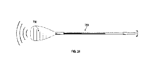
100521 FIG. 24 illustrates one possible
embodiment for the control mechanism 680.
In this embodiment the control mechanism is encapsulated in a package 790
which is integrated
into a paddle 780. It will be appreciated by one of ordinary skill in the art
that the term
integrated into the paddle may comprise being attached to the surface or
within the structure
of paddle 780. In one embodiment the package 790 is a watertight package In
one
embodiment, package 790 comprises a plastic box. In another embodiment,
package 790
comprises layers of other materials. Advantageously, this embodiment
facilitates control of the
kayak while maintaining the ability of the user to use her hands for normal
paddling activity.
For example, rather than positioning one hand on a throttle to control the
pump system 800,
the normal motion of the user's paddle can be used to control the pump system
800. For
example, it may be desirable for the motor controller to activate the motors
while the user
would normally be paddling. Accordingly, when the control mechanism is
embedded in a
paddle 780, the control mechanism may be configured to recognize the
acceleration
experienced by a user's paddle during the paddling motion as a command to
engage the motors.
Alternatively, the control mechanism may be configured to activate the motors
in response to
patterns which, though not necessarily paddling related, require less effort
or distraction than
involved in manually manipulating a throttle. For example, while paddling,
rather than
adjusting a throttle, the user might simply shake her paddle 780 to engage or
disengage the
motor. Accordingly, the user is able to control the motors of the kayak with
less effort and
coordination than would be required to manipulate the throttle embedded in
body of a kayak.
In an alternative embodiment, the packaged control mechanism 790 may also be
attached to or
integrated into a wrist strap, glove, or other clothing or accessory.
[0053] The electric motor 801 may be mounted
to plate 805 at an angle with respect
to the horizontal. In some embodiments, the angle may be any angle less than
900 from the
horizontal. For example, the angle may be about 100, 150, 20', 25', 30', 35",
40', and/or about
45 from horizontal. The electric motor 801 may include an electric motor
drive 809 that is
coupled to a motor-side pulley 807. The motor-side pulley 807 may be coupled
to a drive shaft-
side pulley 808 with a belt 802. The drive shaft-side pulley 808 may be
coupled to a drive shaft
813. The drive shaft 813 may pass through a water-tight passageway such that
water cannot
pass from the flow path 825 into the watertight enclosure 827. A similar
construction is shown
in FIG. 4 and described above.
-9-
CA 03151063 2022-3-11
WO 2021/050212
PCT/US2020/046672
100541 As shown in FIG. 2, the motor shaft or
output shaft may be positioned on
axis B and the drive shaft may be positioned on axis A. The two axes may be
substantially
parallel. In addition, the electric motor 801 may be positioned above and
overlap at least a
portion of the drive shaft 813. Thus, when looking down into the housing 820
in the direction
of arrow C, the motor is at least partially superimposed over the drive shaft.
In some
embodiments, the two axes need not be parallel. In some embodiments, the
electric motor 801
may be mounted below the drive shaft 813_ In some embodiments, the electric
motor 801 and
the drive shaft 813 may be mounted side by side. The drive shaft 813 may be
coupled to an
impeller positioned within the flow path 825. In the illustrated embodiment
the impeller and
the electric motor 801 are both mounted on the same side of the plate 805_ In
this confiaurationõ
the electric motor 801 and impeller are both located rearward from the belt
802, that is, closer
to the rear water exhaust port Si. In some embodiments, the motor shaft and
drive shaft 813
can be configured in a linear arrangement (for example both the motor shaft
and the drive shaft
813 are on the same axis). In other embodiments, the motor shaft is installed
in a direct drive
orientation (for example the motor shaft connects directly to the impeller).
In some
embodiments, a belt 802 and drive shaft 813 are eliminated in a direct drive
orientation. In
other embodiments, the impeller and motor shaft are connected through common
mechanical
connectors (for example shaft couplers and bearings) when in a direct drive
orientation. A
larger electric motor drive 809 can be used with the electric motor 801 when
the electric motor
801 is installed in a direct drive or linear orientation. A larger electric
motor drive 809 can
increase the efficiency of the pump system 800, as the pump system 800 can
move the similar
amounts of water as other pump system arrangements with less amp draw.
[0055] As described above and shown again in
FIG. 2, the flow path 825 includes
a water intake port 810 and a water exhaust port 812. The flow path may be
formed by the
removable pump body 804 coupled to a flow housing 803 at interface 855. In
this embodiment,
the removable pump body 804 includes water exhaust port 812. The flow housing
803 may
include the intake port 810. The intake port 810 may face in a generally
downward direction
and may draw water up through the intake port 810 and into the flow path. The
intake port 810
may be at least partially covered by one or more grates. An impeller,
positioned in the flow
path 825, may be rotated causing water to be drawn up though the intake port
810 and directed
-10-
CA 03151063 2022-3-11
WO 2021/050212
PCT/US2020/046672
through the flow housing 803 towards the water exhaust port 812. Water can
then flow past
the impeller and out of the water exhaust port 812.
(00561 In some embodiments, the pump system
800 is powered with compressed
air. In some of these embodiments, the pump system 800 includes a pneumatic
motor within
the drive system. The pneumatic motor can replace the electric motor 801
within the drive
system and can be linked and coupled to other pump system 800 components in a
similar way
as the electric motor 801. Compressed air can be supplied to the pneumatic
motor, which is the
fuel source for the pneumatic motor. The power from the pneumatic motor drives
the drive
shaft 813, either through a direct drive arrangement or through an indirect
arrangement, which
in turn powers the impeller and causes water to be drawn and expelled through
the flow path
825. In some of these embodiments, canisters holding compressed air can be
stored within the
kayak 883. These canisters can be made from carbon fiber or other lightweight
material. The
canisters can couple to the pneumatic motor through an air hose, which links a
valve from the
canister to a valve within the pneumatic motor. In some embodiments, a user
can replace a
depleted canister with a new canister by disconnecting the air hose from the
depleted canister
and connecting the hose to the new canister. In some embodiments, the canister
can form a
stress member of the kayak 883. In some of these embodiments, the canister can
be utilized as
a container for compressed air and form a part of the kayak 883 body. For
example, the canister
can take the shape of a side of the kayak 883. When assembled, the canister
can be installed as
the side of kayak 883. The canister can take the shape of other parts of the
kayak 883 besides
a side of the kayak 883, such as, for example, the hull, bow, and stem. In
some embodiments,
the canisters can replace the need for the pump system 800 to house batteries.
In some
embodiments, the pump system 800 may include both an electric motor 801 and
pneumatic
motor. In some of these embodiments, both the electric motor 801 and pneumatic
motor can
be used to operate the same impeller. In other embodiments, the electric motor
801 is used in
one pump system 800 while the pneumatic motor is used in a second pump system
800.
100571 FIG. 4 illustrates the pump system 800
shown with the cover 821 removed,
partially showing the interior of the housing 820. The plate 805 and electric
motor 801 can be
seen.
100581 FIG. 5 illustrates a pump system 800
installed within an opening in the
kayak 883. In FIG. 5, only a portion of the kayak 883 is shown, the bow and
stem of the kayak
-11-
CA 03151063 2022-3-11
WO 2021/050212
PCT/US2020/046672
are omitted. The kayak 883 shown in FIG. 5 may be substantially similar to the
kayak 883 of
FIG. 12, where a complete view of the kayak 883 is provided. As discussed
above, many
commercially available kayaks have one Of more openings formed there through.
The openings
may be used to bail water from the kayak and/or to gain access to the water.
For example,
fishing equipment and/or fish finding equipment may be inserted into and
secured within such
openings.
100591 In the partial view of FIG 5, the pump
system 800 is removed from the
opening 889 in the kayak 883. The opening 889 may be formed in the body of the
kayak 883
and configured in size and shape to receive the pump system 800. In other
words, the pump
system 800 is configured to be inserted into the opening 889. In some
embodiments, the
opening 889 extends entirely through kayak 883, while in other embodiments,
the opening 889
is merely a recess, extending only partially through the kayak 883. In some
embodiments, the
opening 889 may be a pre-fabricated opening formed in commercially available
kayaks. In
some embodiments, the opening 889 may be cut into an existing kayak in a shape
that is
configured to receive the pump system 800.
100601 As shown, the intake port 810 is
facing in a downward direction (in other
words, away from the bottom surface of the kayak 883). In some embodiments,
the pump
system 800 includes an underside having a substantially planar surface and the
intake port 810
is positioned on the substantially planar surface. One or more grates 1693 may
be positioned
over the intake port 810. In the embodiment shown in FIG. 5, the underside of
the pump system
800 also includes the securement plate 890. The securement plate 890 may be
sized such that
the securement plate 890 extends out from the opening 889 in the kayak 883.
That is, the
securement plate 890 at least partially overlaps the bottom surface of the
kayak 883 when the
pump system is inserted into the opening 889. The securement plate 890 may be
secured to the
underside of the kayak 883 to hold the pump system 800 in place. In this way,
the pump system
800 may be inserted into the opening 889 in the kayak 883 from below. However,
in other
embodiments, the pump system 800 may be sized and shaped such that it is
insertable from
above. In other embodiments, the pump system 800 may be sized and shaped such
that it is
insertable from above and below. The pump system 800 may be secured to the
kayak 883 at
the top side and/or the bottom side of the kayak 883. In some embodiments, the
water intake
port 810 may be configured to extend perpendicular (or at some other angle
less than
-12-
CA 03151063 2022-3-11
WO 2021/050212
PCT/US2020/046672
perpendicular) to the bottom side of the kayak 883. For example, in some
embodiments, the
flow path 825 may comprise a substantially straight tube extending below the
kayak 883 and
parallel to the bottom side of the kayak 881
(0061) FIG. 6 is a partial perspective top-
side view of the kayak 883 having an
opening 889 there through. Again, the kayak 883 may be substantially similar
to the kayak 883
shown in FIG. 12. In FIG. 6, various recesses and other features formed in the
body of the
kayak 883 are illustrated. However, these features need not be present in all
embodiments.
Moreover, the stem and the bow of the kayak 883 are not shown. The portion of
the kayak 883
illustrated in FIG. 6 may represent a portion of the kayak towards the bow of
the kayak, in the
middle of the kayak, or towards the stem of a kayak, or any other portion
there between.
Accordingly, in various embodiments, the opening 889 for receiving the pump
system 800 may
be located at various positions along the length of the kayak. In some
embodiments, the
opening may be centered over the keel of the kayak, that is, centered across
the kayak's width.
However, this need not be the case in all embodiments. As shown, the opening
889 extends
through the kayak 883 and is surrounded by sidewalls. The sidewalls may
prevent the egress
of water into other areas of the kayak 883. The pump system 800 may be
configured to be
easily inserted and removed from the opening 889. In this way, the opening 889
may be used
for multiple purposes. For example, a user can insert the pump system 800 into
the opening
889 to integrate a propulsion source into the kayak, or the user may remove
the pump system
800 from the opening 889 and use the opening 889 for another purpose, for
example, with a
fish finder or to drain water from the kayak 883. In some embodiments, the
pump system 800
may be easily removed for service. In some embodiments, the pump system 800
may include
one or more rechargeable batteries. The pump system 800 may include a charging
port (for
example port 889 in FIGS_ I A and 1B) and/or a battery management system. In
some
embodiments, the pump system 800 may be removed from the kayak 883 in order
for the
batteries to be charged using a wall outlet. In some embodiments, the pump
system 800 can be
separated from the battery management system_ For example, a user can remove
the battery
management system while leaving the remaining pump system 800 intact and
connected with
kayak 883. The user could charge the battery management system while the
battery
management system is disconnected from the pump system 800 and/or replace the
removed
battery management system with a second battery management system_
- I 3-
CA 03151063 2022-3-11
WO 2021/050212
PCT/US2020/046672
100621 FIG. 7 is a partial perspective top-
side view of a kayak 883 having a pump
system 800 inserted through the opening 889 in the kayak 883. In the
illustrated embodiment,
the portion of the kayak 883 shown is the same as that shown in FIG. 6. As
shown, the cover
821 of the housing 820 has been removed and the electric motor 801 and belt
drive 802 can be
seen. As shown in FIG. 8, in some embodiments a plurality of batteries 950 may
be positioned
on top of the pump system 800. The batteries 950 may be held in place by the
sidewalk
surrounding the opening 889 in the kayak 883. The batteries 950 may include a
separate
housing and/or may be located anywhere on or within the kayak 883, including
within the
housing 820. In some embodiments, batteries 950 may be located at a distance
away from the
where the pump system 800 is installed within the kayak 883. As such, a length
wiring may be
needed to connect the batteries 950 to the pump system 800. In some
embodiments, the wiring
may extend down through an opening or scupper hole within the kayak 883 and
along the
underside of the kayak 883 and connected to an underside of the pump system
800.
[0063] In some embodiments, a second pump
system 800 can be positioned next to
a first pump system 800. In these embodiments, the second pump system 800 is
identical to
the first pump system 800 and is positioned within the same opening 889, In
these
embodiments, both the first and second pump systems 800 can operate
independently of each
other. Thus, the first pump system 800 can operate while the second pump
system 800 is
disabled and vice versa. Additionally, both pump systems 800 can operate
simultaneously. In
some embodiments, the dual pump system 800 can utilize a single exhaust port.
In these
embodiments, water received from either intake value 8110 of the first and
second pump system
800 is expelled out a single exhaust port 812.
[0064] The pump system 800 described herein
can be scaled in size to meet the
requirements of larger and smaller watercraft For example, when installed in a
larger
watercraft (for example yacht), the pump system 800 can include larger
components, such as
a larger motor 801, pump body 804, intake port 810, and exhaust port 812, so
as to allow the
pump system 800 to move more water through the pump system SOO. The pump
system can
also be powered with different power sources when the size of the pump system
is changed.
For example, in a smaller watercraft (for example pool toy), the pump system
800 can be
powered from common household batteries (for example AA batteries), whereas in
a larger
watercraft, the pump system can be powered off of a large external power
source (for example
-14-
CA 03151063 2022-3-11
WO 2021/050212
PCT/US2020/046672
the yacht's battery or power source). Other modifications can be made to the
pump system 800
so the pump system 800 can accommodate different sized watercraft. For
example, the pump
system 800 can be installed in multiple locations along the underside of a
watercraft. In some
embodiments, the pump system 800 can be installed near both the bow and stern
of the
watercraft. In other embodiments, the pump system 800 can be installed near
both the port and
starboard sides of the watercraft. Installing the pump system 800 at different
locations on a
watercraft can improve maneuverability. For example, installing a pump system
800 on the
starboard side of the watercraft can allow an operator to (1) propel the
watercraft forward and
(2) turn the watercraft to the left. In other embodiments, 2, 3, 4, 5, 6, 7,
8, 9, or 10 pump
systems 800 can be installed in the watercraft Other modifications can include
installing a
diverter (for example diverter plate) at the end of the exhaust port 812 so
that thrust from the
pump system 800 can be directed in a new direction (for example left, right,
or rearward of the
exhaust port 812). In some embodiments, the exhaust Ron 812 can be connected
to a joint or
hinge, which allows the pump system to change the direction of the thrust by
pivoting the
exhaust port 812. In some embodiments, the pump system 800 can be used to
stabilize a
watercraft. For example, the exhaust port 812 can be installed in a vertical
orientation, allowing
the pump system 800 to direct thrust in a downward or upward direction.
Directing thrust
downwards or upwards can stabilize a watercraft by preventing the watercraft
from rocking.
100651 FIGS. 9-11, 14-16 depict a pump system
800 connected to the bottom of
kayak. The pump system 800 depicted in FIGS. 9-11, 14-16 is substantially
similar to the pump
system depicted in FIGS. 1A-8 above. Both pump systems can have the same
components and
can operate in the same manner. However, the pump system 800 can be positioned
within the
kayak in a different manner,
[0066] As shown in FIGS_ 9-11, 14-16, the
pump system 800 is installed within a
recess 887 of the kayak 883. The recess 887 is an indent or space in the base
891 of the kayak
883. In some embodiments, the recess 887 conforms to the general shape of the
pump system
800. For example, the recess 887 can have an about rectangular shape to
conform to the shape
of the pump housing 820 as depicted in HG. 16. In other embodiments, the
recess 887 forms
a space that allows a pump system 800 to be positioned and installed within.
The recess 887
can be formed when the kayak 883 is manufactured. In some embodiments, the
recess 887 is
formed during a molding process. For example, the mold for a kayak can have
the shape of the
-15-
CA 03151063 2022-3-11
WO 2021/050212
PCT/US2020/046672
recess 887 carved within the mold such that when the mold is used to
manufacture a kayak,
the recess 887 will be formed into the kayak automatically. In other
embodiments, the recess
887 can be machined into a preexisting kayak. In some embodiments, a
combination of using
a mold and machining is used to form a recess 887.
100671 As shown in FIG. 9, when installed,
the pump system 800 may not extend
substantially from the underside of the kayak 883. In seine embodiments, the
pump system
800 extends no more than three inches from the base 891 of the kayak 883. In
other
embodiments, the pump system 800 extends no more than two inches from the base
891 of the
kayak 883. In still other embodiments, the pump system 800 extends no more
than one inch
from the base 891 of the kayak 883. In still other embodiments, the pump
system 800 is flush
with the base 891 of the kayak 883. In some embodiments, because the pump
system 800 does
not extend beyond the base 891 of the kayak 883, the pump system can be
operated anywhere
that the kayak 883 can be, including in shallow water. As further shown in HG.
9, the mounting
plate 890 is secured to the base 891 of the kayak 883. The mounting plate 890
is used to secure
the pump system 800 to the kayak 883 while the pump system 800 is positioned
within the
recess 887, The mounting plate secures the pump system 800 to the kayak 883
through
common fasteners (for example bolt and nut) or with a sealant (for example
silicon). Additional
views of portions of the underside of the kayak 883 with installed pump system
800 are shown
in FIGS. 10 and 11.
[0068] FIGS. 14-16 depict a bottom view of
the pump system 800. As shown in
FIGS. 14-16, the exhaust port 812 can be positioned within a recess 816. The
recess 816 has a
base 817 with two sidewalls 818 extending out from the base. In some
embodiment, the base
817 is about parallel with the base 891 of the kayak 883. As shown in FIG. 16,
the base 816
can be angled upwards at about 30 degrees with respect to the base 891 of the
kayak 883. In
some embodiments, the sidewalk 818 are about perpendicular with the base 81T
In other
embodiments, the sidewalts 818 are angled outwards from perpendicular_ The
sidewalk can
be angled outwards from about perpendicular to about 120 degrees with respect
to the base
817. As shown in FIG. 15, the recess 816 can form a V-shape, or U-shape,
profile. This profile
is formed due to the sidewalls 818 being wider towards the base of the exhaust
port 812 and
narrower towards the end of the recess 816. This profile can increase thrust
by constricting
water as it exits the exhaust port 812. In some embodiments, sidewalls 818 are
narrower at the
-16-
CA 03151063 2022-3-11
WO 2021/050212
PCT/US2020/046672
base of the exhaust port 812 and wider towards the end of the recess. In other
embodiments,
the sidewalls are about parallel with respect to each other. Positioning the
exhaust port 812
within the recess 816 can increase the pump system's 800 efficiency by
reducing drag. In some
embodiments, water may be expelled from the exhaust port 812 towards the
recessed portion
816 to create a Coanda Effect. As used herein, the term "Coanda Effect" refers
to the tendency
of a fluid jet to be attracted to a nearby surface, for example, the recessed
portion 816. During
operation, bubbles can form on the base 891 of the kayak 883 as the exhaust
port 812 expels
water. These bubbles create a slippery surface on the base 891 of the kayak
883, which reduces
drag. This slippery surface effect can be increased by positioning the exhaust
port 812 toward
the middle or the bow of the kayak 883. Positioning the exhaust port towards
the middle or
bow of the kayak 883 reduces drag for more of the base 891 of the kayak 883,
as the bubbles
will travel across more of the base 891.
100691 As shown in FIG. 14, the exhaust port
812 can have an oval-shaped end
815. The oval-shaped end 815 can increase thrust from water expelled from the
exhaust port
812. The oval-shaped end 815 operates as a nonintrusive flow straightener. As
a result, the
water expelled from the exhaust port 812 forms a tight rope and maintains the
tight rope shape
over a long distance (for example, about 25 feet). By creating a tight rope of
water that holds
its shape over long distances, the exhaust port 812 increases the thrust and
efficiency from the
pump system 800. In some embodiments, the water exhaust port 812 has a
constricted end.
The constricted end can increase the acceleration of the water as it flows out
of the water
exhaust port 812.
100701 The pump housing 820 extends into the
recess 887 of the kayak 883. In
some embodiments, the pump housing 820 does not extend into the cockpit and is
instead fully
contained within the recess 887. In some embodiments, when the pump system 800
is mounted
to the kayak 883, the pump system 800 forms a watertight seal with the kayak
883 at the recess
to prevent water from entering into the recess. In some embodiments, a hood is
placed over the
part of the pump housing 820 that is positioned within the recess 887. The
hood will form a
watertight seal with the pump components to prevent water from entering into
the pump
housing 820. In other embodiments, the recess 887 has an opening to allow
access to the
cockpit. The opening can be positioned anywhere within the recess 887 and is
sized allow for
wiring to travel into the cockpit. The wiring can be used to connect
controllers, external
-17-
CA 03151063 2022-3-11
WO 2021/050212
PCT/US2020/046672
batteries, and other devices to the pump system 800. In some embodiments, a
post extends
from the cockpit and through the opening. Wiring can be placed within the
post. In some
embodiments, a user can remove the external batteries while within the cockpit
without having
to uninstall the pump system 800. The user can then charge the external
batteries or replace
the external batteries without having to uninstall the pump system 800.
100711 In some embodiments, grate 300 can be
installed over the intake port 810.
Grate 300 can be sized and shaped to cover the intake port 810 and intake port
recess 814. For
example, as shown in FIGS. 25-26, grate 300 is oval shaped and can cover both
the intake port
810 and the intake port recess 814 depicted in FIG. 16. Grate 300 can have
several openings
302 formed on the face 301 of the grate 300 that extend through the grate 300.
The openings
302 can be arranged in a checkered pattern, as depicted in FIGS_ 25-26, and
can extend across
the most of the grate 300. In some embodiments, the openings 302 do not cover
most of the
grate 300, and instead cover only a part of the grate 300, such as, for
example, about one-
quarter, one-third, one-half, two-thirds, or three-quarters of the grate 300.
In some
embodiments, the openings 302 are arranged in a different pattern, such as,
for example, linear
or swirl. The openings 302 are formed at an angle with respect to the face
301. The openings
302 can be formed at an angle of about 5, 10, 15, 20, 25, 30, 35, 40,45. 50,
55, or 60 degrees.
In some embodiments, the openings 302 are tapered. Forming the openings 302 at
an angle or
tapering the openings 302 improves the grate's 300 ability to prevent objects
from Hocking
the intake port 810 while still allowing water to enter the intake port 810.
To further improve
the intake port's 810 ability to intake water, the intake port 810 can be
installed in a tilted
position, as shown in FIG. 16 for example, so that the intake port 810 is
substantially parallel
with the openings 302. In other embodiments, the grate 300 is installed in a
tilted position so
that the intake port 810 is substantially parallel with the openings 302.
Because the openings
302 are about parallel with intake port 810, water can enter the intake port
810 unobstructed.
In some embodiments, the intake port 810 is installed so the intake port 810
is not parallel with
the openings 302 so as to further prevent debris from entering into the intake
port 810 The
grate 300 can be formed from a number of materials, which can include, for
instance, metal
(for example, aluminum or steel), metal alloy (for example, aluminum alloys),
carbon fiber
reinforced plastic, or a plastic material. The grate 300 can be manufactured
using a variety of
different materials and methods. The grate may be made by any suitable
process, such as, for
-18-
CA 03151063 2022-3-11
WO 2021/050212
PCT/US2020/046672
instance, machining, milling, water jet cutting, laser cutting, stamping,
pressing, sheet metal
drawing, molding (for example, injection molding), casting, rapid prototyping
using additive
manufacturing techniques, or any combination thereof
(0072) In some embodiments, a user can remove
the batteries from the pump
system 800 without uninstalling the pump system 800 from the kayak 883 (for
example,
removing the pump system 800 from the recess 887). In some of these
embodiments, the
batteries are located in a compartment within the pump housing 820. The
battery compartment
is installed on the exterior of the pump housing 820. In some embodiments, the
compartment
is installed into the pump housing 820 by forming a threaded connection
between the
compartment and the pump housing 820. In other embodiments, the battery
compartment is
installed through other methods, including, but not limited to, fasteners, key
and pin, and
latches. When installed, the compartment is partially exposed on the underside
of the kayak
883, allowing a user to access and uninstall the compartment without
uninstalling the pump
system 800. In some of these embodiments, the user only needs to remove the
battery
compartment from the kayak 883 and can leave the rest of the pump system 800
installed In
some embodiments, a user can charge the batteries while the batteries remain
in the pump
system 800. In some of these embodiments, the user charges the batteries
through a charging
port, similar to the charging ports described herein, on the pump system.
100731 FIGS. 28-33 depict a pump system 1000
configured to be placed within a
recess 1106 of a kayak 883, 1300. In some embodiments, the pump system 1000
depicted in
FIGS. 28-33 is substantially similar to the pump system 800 depicted in FIGS.
1A-8, 9-11, and
14-16 above. These pump systems 800, 1000 can operate in the same or similar
manner and
produce the same or similar operational results. However, in some embodiments,
the pump
system 1000 includes different components_
(0074) In some embodiments, the pump system
1000 includes a hatch 1002, a
power unit body 1008, a motor 1006, motor contacts 1004, a drive shaft 1012, a
shaft cover
1010, an impeller 1014, a flow straightener 1016, and a pump nozzle 1018. The
hatch 1002
can connect to the power unit body 1008 through a snap fit, friction fit,
bonding, or other
mechanical means. In some embodiments, the connection between the hatch 1002
and the
power unit body 1008 forms a watertight seal that prevents water from entering
inside the hatch
1002 or power unit body 1008. Installed inside the power unit body 1008 is the
motor 1006_
-19-
CA 03151063 2022-3-11
WO 2021/050212
PCT/US2020/046672
The motor may be sealed between the power unit body 1008 and the hatch 1002
when the
hatch 1002 is installed on the power unit body 1008. The shaft cover 1010 may
connect to the
lower section of power unit body 1008. The shaft cover 1010 can form a
watertight seal with
the power unit body 1008 so as to prevent water from entering inside the power
unit body
1008. The drive shaft 1012 maybe configured to be installed within the shaft
cover 1010. The
drive shaft 1012 connects to the motor 1006. In some embodiments, the drive
shaft 1012
connects to the motor 1006 by being installed in a direct drive arrangement
with the motor
1006. In other embodiments, the drive shaft 1010 connects to the motor 1006
through a gear
box or belt system. In some embodiments, the drive shaft 1012 can contain one
or more 0-ring
or other sealant placed on the outer half of the drive shaft The 0-ring or
sealant can prevent
water from entering inside the power unit body 1008 through the inside of the
shaft cover 1010.
Connected to the end of the drive shaft 1012 is an impeller 1014. The impeller
1014 can be
installed on the end of the drive shaft 1012 through several mechanical means,
including, for
example, threading onto the drive shaft, bonding, welding, snap fit, or
friction fit In some
embodiments, the impeller 1014 is an axial impeller. In some embodiments, the
impeller 1014
has a symmetrical design, where the blades of the impeller 1014 are
symmetrical about the
centerline. This symmetrical design allows the blades of the impeller 1014 to
create the same
flow pattern no matter which side of the impeller 1014 is mounted to the drive
shaft 1012. The
flow straightener 1016 is installed on one end of the impeller 1014. In some
embodiments, the
flow straightener does not contact the impeller 1014 when installed within the
pump system
1000. In some of these embodiments, the flow straightener 101.6 is positioned
within the power
unit body 1008. In other embodiments, the flow straightener 1016 is installed
within the pump
nozzle 1018. The pump nozzle 1018 connects to the power unit body 1008. In
some
embodiments, the pump nozzle 1018 is installed on a lower end of the power
unit body 1008.
(0075) The pump system 1000 may use other
components as well. For example,
the power unit body 1008 can further house a motor controller, one or more
batteries, an air
pump, a wireless receiver, a wireless transmitter, one or more motor control
systems, battery
control systems, and/or sensors (including water sensors), among other
components.
(0076) The pump system 1000 can be installed
inside a recess 1106 of a kayak 883,
1300. The recess 1106 can be formed on the base 1301 of a kayak 1300. A recess
wall 1100
can extend upward from the base 1301 of the kayak 1300. The recess wall 1100
is sized and
-20-
CA 03151063 2022-3-11
WO 2021/050212
PCT/US2020/046672
shaped in a manner that allows for the pump system 1100 to be placed within
the recess 1106
so that bottom section of the power body unit 1008 is about flush with the
base 1301 of the
kayak 1300, as depicted in FIGS. 30-32. In some embodiments, the recess 1106
and recess
wall 1100 is substantially similar to the recess 887 described herein. Once
positioned within
the recess 1106, the pump system 1000 can be held in place through various
mechanical and
chemical means, including, for example, clamps, fasteners, bonding, welding,
friction fit, or
snap fit. In some embodiments, a mounting plate is used to mount and hold the
pump system
1000 in place. Once installed, the pump system 1000 can form a watertight seal
with the recess
wall 1100 so as to prevent water from entering into the recess 1106. In some
embodiments, a
grate 1200 can be placed over the front compartment 1020. The grate 1200 can
have one or
more (for example, 2, 3, 4, 5, 6, 7, 8, 9, 10, or more) bars extending across
the front
compartment 1020. The grate 1200 can prevent or restrict debris from entering
into the pump
system 1000 while still permitting water to enter into the pump system 1000.
In some
embodiments, the grate 1200 can be replaced with the grate 300 described
herein. The motor
contacts 1004 can contact and form a connection with the motor controller
1102. The motor
controller 1102 can be accessible to a user of the kayak 1300 while the user
is seated within
the kayak 1300. In some embodiments, the user will need to remove an access
hatch to access
the motor controller 1102. In other embodiments, the motor controller 1102 is
readily
accessible to the user without the user needing to remove or open any
additional equipment.
The motor controller 1102 can be connected to an external battery through a
set of cables 1104.
Because the external battery is connected to the cables 1104, the external
battery can be
installed within the kayak 1300 at multiple locations, including locations
that allow the external
battery to be easily accessible by the user. In some embodiments, a user can
replace the external
battery without having to uninstall any part of the pump system 1000. The
external battery can
be used to power the motor 1006. Once the external battery is installed, the
motor controller
1102 can distribute power to the motor 1006.
/00771 The pump system 1000 operates by
drawing water in through the front
compartment 1020 on the power unit body 1008. Water is drawn into the front
compartment
1020 due to the motor 1006 driving the impeller 1014. In some embodiments, the
impeller
1014 reduces the pressure of the water, creating suction downstream of the
impeller 1014 (e.g.
creates suction near the front compartment 1014). Reducing the water pressure
draws the water
-21-
CA 03151063 2022-3-11
WO 2021/050212
PCT/US2020/046672
through the front compartment 1020 and into the power unit body 1008. The
water drawn into
the front compartment 1020 travels over the impeller 1014, which assists with
moving the
water through the pump system 1000. After the water travels over the impeller
1014, the water
travels over the flow straightener 1016, causing the water to form a laminar
flow (e.g. the flow
straightener reduces or removes the spin on the water created by the
impeller). The water then
exits the pump system 1000 at the pump nozzle 1018, creating a jet of water
that propels the
kayak 1300 forward. In some embodiments, water can be drawn in through the
pump nozzle
1018 and expelled out of the front compartment 1020. In some of these
embodiments, the
motor 1006 can spin the impeller 1014 in the opposite direction of normal
operation. Spinning
the impeller 1014 in the opposite direction can lower the water pressure on
the opposite side
of the impeller /014 (e.g. on the side near the pump nozzle 1018), causing
water to be drawn
in through the pump nozzle 1018 and directed to the front compartment 1020.
This reverse
flow creates thrust in the reverse direction, propelling the kayak 1300 in the
aft direction. The
pump system 1000 can be controlled through the motor controller 1102. In some
embodiments,
the motor controller 1102 can be configured to control the pump system 1000 in
a manner as
described with other embodiments herein. For example, the motor controller
1102 may be
configured to activate or deactivate the motor 1006, control the speed of the
motor 1006 and/or
the amount of power supplied to the motor 1006, and/or control other motor
1006 functions.
By adjusting the power of the motor 1006, a user can adjust the thrust a pump
system 1000
produces. The motor 1.006 can receive power through an external power source,
such as an
external battery. The external battery can be connected to the pump system
1000 through cables
1104.
[0078] In some embodiments, the recess 1106
can have sidewalls and a base. These
sidewalk and base can be shaped similarly to the sidewalls 818 and a base 817
described
herein. For example, the recess 1106 can form a V-shape or U-shape profile on
the end near
the pump nozzle 1018. This profile can increase thrust by constricting water
as it exits the
pump nozzle 1018. In some embodiments, water may be expelled from the pump
nozzle 1018
towards the sloped area of the recess 1106 to create a Coanda Effect. During
operation, bubbles
can form on the base 1301 of the kayak 1300 as the pump nozzle expels water.
These bubbles
create a slippery surface on the base 1301 of the kayak 1300, which reduces
drag. This slippery
surface effect can be increased by positioning the pump nozzle 1018 toward the
middle or the
-22-
CA 03151063 2022-3-11
WO 2021/050212
PCT/US2020/046672
bow of the kayak 1300. Positioning the pump nozzle 1018 towards the middle or
bow of the
kayak 1300 reduces drag for more of the base 1301 of the kayak 1300, as the
bubbles will
travel across more of the base 1301.
[00791 In some embodiments, the pump nozzle
1018 can have an oval-shaped end.
The oval-shaped end can be similar to the oval-shaped end 815 described herein
in both size
and function. For example, the oval-shaped end can increase thrust from water
expelled from
the pump nozzle 1018. The oval-shaped end can operate as a nonintrusive flow
straightener
As a result, the water expelled from the pump nozzle 1018 forms a tight rope
and maintains
the tight rope shape over a long distance (for example, about 25 feet). By
creating a tight rope
of water that holds its shape over long distances, the pump nozzle 1018 can
increase the thrust
and efficiency from the pump system 1000_ In some embodiments, the pump nozzle
1018 has
a constricted end (e.g. one end is narrower than the other end). The
constricted end can increase
the acceleration of the water as it flows out of the pump nozzle 1018.
[0080] In some embodiments, the pump system
1000 can powered by compressed
air. In some of these embodiments, the motor 1006 is a pneumatic motor which
can be powered
by air. The cables 1104 can connect to an air tank and the motor controller
1102 can assist with
regulating air flow to the motor. In some embodiments, a second pump system
1000 can be
installed on base 1301 of a kayak 1300. The second pump system 1000 can
function
substantially similar to the first pump system 1000. In some embodiments, the
first and second
pump systems 1000 can operate and be constructed similarly to the dual pump
system 200
described herein.
100811 FIGS. 17, 18, and 27 depict a dual
pump system 200 that can be placed
within a recess 210 of a kayak 883. The dual pump system 200 has a housing 201
which can
hold two pump systems 800. As depicted in FIGS. 18, 27, the pump systems 800
can share a
sidewall 203, which separates the pump systems into individual compartments.
In some
embodiments, the dual pump system does not have a sidewall 203 and the pump
systems 800
share a single compartment. The dual pump system 200 can be placed within a
dual recess 210õ
such as, for example, the dual recess 210 depicted in FIG. 27. The dual recess
210 can include
two or more individual recess 211, 212, with those individual recesses 211,
212 being sized,
shaped, and functionally similar to recess 887 described herein. In some
embodiments, the dual
pump system 200 is generally the size of the dual recess 210. In other
embodiments, the dual
-23-
CA 03151063 2022-3-11
WO 2021/050212
PCT/US2020/046672
recess 210 is slightly larger than the dual pump system so that the dual pump
system 200 can
be positioned within the dual recess 210 without contacting the walls of each
individual recess
211, 212. In other embodiments, the dual recess 210 is a single, large space
with no
compartment wall 213 in-between the individual recesses 211, 212. Once
installed within the
dual recess 210, the housing 201 forms a watertight seal with the base 891 so
that the recess
887 is sealed. In other embodiments, a hood is placed over the pan of the
housing 201 that is
positioned within the dual recess 210. The hood will form a watertight seal
with the pump
components to prevent water from entering into the pump housing 820. Both the
first and
second pump systems 800 can operate independently of each other. Thus, the
first pump system
800 can operate while the second pump system 800 is disabled arid vice versa.
Additionally,
both pump systems 800 can operate simultaneously. In some embodiments, the
dual pump
system 200 can utilize a single exhaust port 812. In these embodiments, water
received from
either intake value 810 of the first and second pump system 800 is expelled
out a single exhaust
port 812. The dual pump system can be secured to the recess 210 by using the
mounting studs
202 located throughout the housing.
100821 FIGS, 19 and 20 depict a pump system
1620, When installed, the pump
system 1620 connects to the base of kayak while positioned within a recess
887. In one
embodiment, the recess 887 forms a tear-drop shaped aperture in the base 891.
The tear-drop
shaped aperture may be complimentary to the shapes of the insert 1614 and/or
pump system
1620 such that the insert 1614 and/or pump system 1620 can be oriented andlor
positioned in
a desired configuration within the recess 887,
100831 The insert 1614 may comprise a solid
or substantially ring-shaped sheet
structure configured to cover at least a portion of the recess 887. The insert
1614 may be
coupled to the recess 887 using various coupling means, for example,
adhesives, bonding
agents, and/or fasteners. In some embodiments, by virtue of the complimentary
shapes of the
insert 1614 and the recess 887, the insert 1614 may be form fitted within the
recess 887 such
that the engagement there between inhibits longitudinal, lateral, and/or
transverse motion of
the insert /6/4 relative to the recess 887. When disposed within the recess
887, the insert 1614
can define a receiving space 1616 for receiving the pump system 1620.
100841 In some embodiments, the insert 1614
may include one or more protrusions
1651 configured to be inserted into one or more indentations 1659 (shown in
FIG. 19) on the
-24-
CA 03151063 2022-3-11
WO 2021/050212
PCT/US2020/046672
pump system 1620. The protrusions 1651 and indentations 1659 on the pump
system 1620 can
have complimentary shapes such that the protrusions may be received by the
indentations by
sliding the pump system 1620 forward longitudinally relative to the insert
1614.. The
engagement of the protrusions 1651 and corresponding indentations can result
in one or more
abutments that act to arrest or inhibit longitudinal, lateral, and/or
transverse movement of the
pump system 1620 relative to the insert 1614 and body 1600.
100851 The insert 1614 may also include a
latch element 1653 that is cantilevered
from a latch plate 1655. The latch element 1653 may catch one or more surfaces
within a
receptacle 1661 (shown in FIG. 8) on the pump system 1620 when the pump system
1620 is
received within the insert 1614 to secure the pump system 1620 in the
longitudinal direction
relative to the insert 1614. In this way, the pump system 1620 may be slid
forward into the
insert 1614 until the latch 1653 releasably engages a notch or other feature
on the insert 1614
such that the pump system 1620 is aligned and secured relative to the insert
1614. To remove
the pump system 1620 from the insert 1614, the latch element 1653 may be
depressed by
applying a force to the cantilevered end of the latch element 1653 to
disengage the latch
element from the notch or other feature. Disengaging the latch element 1653
then will allow a
user to slide the pump system 1620 backward longitudinally relative to the
insert 1614 to
release the protrusions 1651 from the indentations 1659.
100861 The base surface 1622 of the pump
system 1620 may be configured to
substantially match the adjacent base 891 of a kayak 883 to achieve a desired
hydrodynamic
profile of the personal watercraft. The base surface 1622 may also include a
charging port 1631
a.ndlor activation switch 1633. Thus, the pump system 1620 may be charged when
the system
is coupled to the kayak 883 or when it is separate from the kayak 883. In
embodiments when
these are provided, the charger port 1631 can be disposed on an opposite side
of the pump
system 1620 and the activation switch 1633 can be disposed elsewhere as well
if desired.
100871 As shown in FIGS. 19 and 20, the pump
system 1620 may comprise a drive
system including one or more motors 1675. In one embodiment, the drive system
can be at
least partially housed between a pump base 1671 and a pump cover 1657. The one
or more
motors 1675 can be powered by one or more batteries 1665 and can be mounted to
the pump
base 1671 by motor mounts 1677. In some embodiments, each motor 1675 can be
coupled to
a motor shaft 1690 by a shaft coupler 1679, shaft bearing 1681, bearing holder
1683, and spacer
-25-
CA 03151063 2022-3-11
WO 2021/050212
PCT/US2020/046672
1685. Each shaft 1690 can be coupled to an impeller 1699 that is disposed at
least partially
within a pump housing 1695 and a bearing 1697 can optionally be disposed
between each shaft
and the impeller 1699. In this way, the one or more motors 1675 can drive each
impeller 1699
to draw water through the pump housing 1695 to propel the pump system relative
to a body of
water.
[00881 In some embodiments, each shaft 1690
can be disposed within a shaft
housing 1694 that is configured to limit the exposure of the shaft 1690 to
objects that are
separate from the pump system 1620. Thus, the shaft housing 1694 can protect a
user from
inadvertently contacting the shaft 1690 during use and/or can protect the
shaft 1690 from
contacting other objects, for example, sea grass. Additionally, the shaft
housing 1694 can
improve performance of the pump system 1620 by isolating each shaft 1690 from
the water
that passes through the pump housing 1695. In some embodiments, each shaft
1690 can be
protected from exposure to the water by one or more shaft seals 1692.
[0089] The pump system 1620 can also include
one or more grates 1693 disposed
over intake ports of the pump housing 1695. In some embodiments, a grate 300
is installed
over the intake ports of the pump housing 1695. The grates 1693 can limit
access to the impeller
1699 and shaft 1690 to protect these components andlor to prevent a user from
inadvertently
contacting these components during use. In some embodiments, each pump housing
1695
and/or grate 1693 can be coupled to one or more magnetic switches (not shown)
that can
deactivate the motors 1675 when the pump housing 1695 and/or grate 1693 are
separated from
the pump base 1671. Therefore, the one or more magnetic switches may prevent
the cassette
from operating without the optional grate 1693 and/or pump housing in place.
[0090] With continued reference to FIGS. 19
and 20, the drive system may also
include one or more motor controllers 1673 for each motor 1675, one or more
relays 1687
configured to connect the one or more batteries 1665 with the one or more
motor controllers
1673, an antenna 1667, and a transceiver 1669_ The one or more motor
controllers 1673, one
or more relays 1687, one or more batteries 1665, antenna 1667, and transceiver
1669, can be
electrically connected to each another by one or more wiring harnesses 1663.
The transceiver
1669 can include or be coupled to wireless transmission circuitry that is
configured to transmit
electromagnetic andlor magnetic signals underwater.
-26-
CA 03151063 2022-3-11
WO 2021/050212
PCT/US2020/046672
100911
FIG. 21 depict a pump system
800 connected to the bottom of the kayak.
The pump system 800 depicted in FIG 21 is substantially similar to the pump
system depicted
in FIGS. 1-11, 14-16 above. These pump systems 800 can have the same
components and can
operate in the same manner. However, the pump system 800 depicted in FIG. 21
can be
installed on the kayak in a different manner.
100921
In FIG. 21, the base 891 of
kayak 883 has a several scupper holes. As used
herein, the term 4 4scupper hole" refers to an opening within a kayak that can
be used to drain
water from the kayak. When installed, the pump system 800 connects to the base
891 of kayak
883 by connecting the pump system to the scupper holes. The pump system 800
connects to
the scupper holes through a rod (not pictured). The rod is attached to the
pump system 800
such that the rod extends in an about vertical direction. When installed, the
rod extends through
a scupper hole and into the cockpit 893. The rod is then secured in the
cockpit and thereby
connecting the pump system 800 to the kayak 883. In some embodiments, the rod
is secured
by using a mounting plate, which secures the rod in place while fastening to
the cockpit 893.
In some embodiments, the rod is secured by tying the rod to a handle or other
device within
the cockpit 893. In some embodiments, the pump system 800 can be mounted to
the kayak
883 using a different number of scupper holes, including, for example, 1, 2,
3, 5, 6, 7, 8, 9, or
scupper holes. In some of these embodiments, multiple rods are connected to
the pump
system 800 and extend through multiple scupper holes. In some embodiments, the
rod is
detachable from the pump system 800 and can be connected to the pump system
800 at
different points along the pump housing 820, allowing a user to select where
the rod is secured.
In some of these embodiments, the rod can be adjusted to accommodate the
scupper hole layout
of different kayaks. In some embodiments, the rod prevents water from entering
the cockpit
893 through the scupper holes. In some of these embodiments, the rod has a
diameter that
pressed against the inside of the scupper hole, which effectively seals the
scupper hole. In other
embodiments, a separate sealant, such as a gasket or cap, can be placed around
the rod and into
the scupper hole, which effectively seals the scupper hole.
[0093]
The rod can include one or
more motor controllers or interface for the
pump motor. The rod can also include relays, batteries, antennas, and
transceivers. The one or
more relays can be configured to connect the one or more batteries with the
one or more motor
controllers an antenna and a transceiver. The one or more motor controllers,
one or more relays,
-27-
CA 03151063 2022-3-11
WO 2021/050212
PCT/US2020/046672
one or more batteries, antenna, and transceiver, can be electrically connected
to each another
by one or more wiring harnesses as discussed above with other figures. In some
embodiments,
the batteries can be removed from the rod without having to remove the rod
from the pump
system 800 or uninstall the pump system 800 from the kayak 883.
100941 Turning now to FIGS. 12 and 13A-F, it
will be understood that in some
embodiments, the pump system 800 may be coupled to the stern of a kayak 883.
For example,
a motor mount 880a, 880b, and 880c may include a receiving space, or pump
housing, in the
bottom side of the motor mount. The receiving space may be shaped to receive
the pump
system 800 inserted from below. A mounting bracket 884 may be positioned over
the transom
of the stem of the kayak 883 and be configured to be coupled to the motor
mount at location
881. The motor mount 880a, 880b, 880c may be rotatable with respect to the
mounting bracket
884. A tiller (not shown) may be coupled to the motor mount 880a, 88013, 880c.
In another
embodiment, foot pedals may be installed in the kayak 883 such that
manipulation of the foot
pedals causes the rotation of the motor mount with respect to the mounting
bracket. In FIG.
12, batteries 950 that power the pump system 800 are located on the kayak 883.
However, as
shown in FIG, 13A-13C, motor mounts may include space for one or more
batteries 950. For
example, FIG. 13 shows the arrangement of a pump system 800 and two batteries
950 within
a motor mount (the motor mount itself is shown in FIG. 13D). FIG. 13B
illustrates an additional
embodiment of an arrangement of two batteries 950 and the pump system 800 (the
corresponding motor mount is shown in FIG 13E). FIG 13C illustrates an
embodiment of an
arrangement of one battery 950 and pump system 800 (the corresponding motor
mount is
shown in FIG. 13F).
[0095] Any of the pump systems described
herein may be configured to turn off
when the pump system is flipped over and/or tossed about in the water. As
such, in some
embodiments, the pump system includes at least one sensor configured to detect
the orientation
and/or movement of the pump system. The sensor may comprise an accelerometer
and/or a
gyroscope. In other embodiments, the senor comprises a sensor configured to
detect water in
the flow path. When there is no water detected in the flow path, the sensor
may cause the motor
to stop. In some embodiments, the sensor is connected to a switch which
disengages the power
supply from the motor when the switch receives a signal from the sensor. In
some
embodiments, the power supply is disconnected from the motor when a gyroscope
detects that
-28-
CA 03151063 2022-3-11
WO 2021/050212
PCT/US2020/046672
the pump system's position is inverted and/or rotated. In some embodiments a
circuit is coupled
to one Of more sensors and configured to disconnect the power source from the
electric motor
based at least in pan on sensor detection of the orientation of the pump
system.
(0096) While certain embodiments have been
described, these embodiments have
been presented by way of example only, and are not intended to limit the scope
of the
disclosure. Indeed, the novel methods and systems described herein may be
embodied in a
variety of other forms. Furthermore, various omissions, substitutions and
changes in the
systems and methods described herein may be made without departing from the
spirit of the
disclosure. The accompanying claims and their equivalents are intended to
cover such forms
or modifications as would fall within the scope and spirit of the disclosure.
Accordingly, the
scope of the present disclosure is defined only by reference to the appended
claims.
(00971 Features, materials, characteristics,
or groups described in conjunction with
a particular aspect, embodiment, or example are to be understood to be
applicable to any other
aspect, embodiment or example described in this section or elsewhere in this
specification
unless incompatible therewith. All of the features disclosed in this
specification (including
any accompanying claims, abstract arid drawings), and/or all of the steps of
any method or
process so disclosed, may be combined in any combination, except combinations
where at least
some of such features and/or steps are mutually exclusive. The protection is
not restricted to
the details of any foregoing embodiments. The protection extends to any novel
one, or any
novel combination, of the features disclosed in this specification (including
any accompanying
claims, abstract and drawings), or to any novel one, or any novel combination,
of the steps of
any method or process so disclosed.
[0098] Furthermore, certain features that are
described in this disclosure in the
context of separate implementations can also be implemented in combination in
a single
implementation. Conversely, various features that are described in the context
of a single
implementation can also be implemented in multiple implementations separately
or in any
suitable subcombination. Moreover, although features may be described above as
acting in
certain combinations, one or more features from a claimed combination can, in
some cases, be
excised from the combination, and the combination may be claimed as a
subcombination or
variation of a subcombi nati on.
-29-
CA 03151063 2022-3-11
WO 2021/050212
PCT/US2020/046672
100991 Moreover, while operations may be
depicted in the drawings or described
in the specification in a particular order, such operations need not be
performed in the particular
order shown or in sequential order, or that all operations be performed, to
achieve desirable
results. Other operations that are not depicted or described can be
incorporated in the example
methods and processes. For example, one or more additional operations can be
performed
before, after, simultaneously, or between any of the described operations.
Further, the
operations may be rearranged or reordered in other implementations. Those
skilled in the art
will appreciate that in some embodiments, the actual steps taken in the
processes illustrated
and/or disclosed may differ from those shown in the figures. Depending on the
embodiment,
certain of the steps described above may be removed, others may be added.
Furthermore, the
features and auributes of the specific embodiments disclosed above may be
combined in
different ways to form additional embodiments, all of which fall within the
scope of the present
disclosure. Also, the separation of various system components in the
implementations
described above should not be understood as requiring such separation in all
implementations,
and it should be understood that the described components and systems can
generally be
integrated together in a single product or packaged into multiple products.
101001 For purposes of this disclosure,
certain aspects, advantages, and novel
features are described herein. Not necessarily all such advantages may be
achieved in
accordance with any particular embodiment. Thus, for example, those skilled in
the art will
recognize that the disclosure may be embodied or carried out in a manner that
achieves one
advantage or a group of advantages as taught herein without necessarily
achieving other
advantages as may be taught or suggested herein.
10101] Conditional language, such as "can,"
"could," "might," or "may," unless
specifically stated otherwise, or otherwise understood within the context as
used, is generally
intended to convey that certain embodiments include, while other embodiments
do not include,
certain features, elements, and/or steps. Thus, such conditional language is
not generally
intended to imply that features, elements, and/or steps are in any way
required for one or more
embodiments or that one or more embodiments necessarily include logic for
deciding, with or
without user input or prompting, whether these features, elements, andlor
steps are included or
are to be performed in any particular embodiment
-30-
CA 03151063 2022-3-11
WO 2021/050212
PCT/US2020/046672
101021 Conjunctive language such as the
phrase "at least one of X, Yõ and Z,"
unless specifically stated otherwise, is otherwise understood with the context
as used in general
to convey that an item, term, etc_ may be either X, Y, or Z. Thus, such
conjunctive language
is not generally intended to imply that certain embodiments require the
presence of at least one
of X, at least one of Y, and at least one of Z.
101031 Language of degree used herein, such
as the terms "approximately,"
"about," "generally," and "substantially" as used herein represent a value,
amount, or
characteristic close to the stated value, amount, or characteristic that still
performs a desired
function or achieves a desired result, For example, the terms "approximately",
"about",
generally," and "substantially" may refer to an amount that is within less
than 10% of, within
less than 5% of, within less than 1% of, within less than 0.1% of, and within
less than 0.01%
of the stated amount. As another example, in certain embodiments, the terms
"generally
parallel" and "substantially parallel" and "about parallel" refer to a value,
amount, or
characteristic that departs from exactly parallel by less than or equal to 15
degrees, 10 degrees,
degrees, 3 degrees, I degree, or 0.1 degree.
101041 The scope of the present disclosure is
not intended to be limited by the
specific disclosures of preferred embodiments in this section or elsewhere in
this specification,
and may be defined by claims as presented in this section or elsewhere in this
specification or
as presented in the future. The language of the claims is to be interpreted
broadly based on the
language employed in the claims and not limited to the examples described in
the present
specification or during the prosecution of the application, which examples are
to be construed
as non-exclusive.
-31-
CA 03151063 2022-3-11