Note: Descriptions are shown in the official language in which they were submitted.
MEASUREMENT CONFIGURATION METHOD, TERMINAL AND
BASE STATION
TECHNICAL FIELD
[0001] The present disclosure relates to the field of mobile
communication
technologies, in particular to a measurement configuration method, a terminal,
and a base
station.
BACKGROUND
[00021 When performing downlink beam measurement, the network side
usually
transmits a Channel State Information Reference Signal (CST-RS) or a
Synchronization
Signal Block (SSB), and User Equipment (UE) receives the CSI-RS or the SSB
through
different receiving beams, to measure a value of Layer 1-Reference Signal
Received
Power (Ll-RSRP) of the CSI-RS/SSB for each receiving beam.
[0003] In the related technologies, it merely defines how the UE
performs LI-RSRP
reporting in current beam quality reporting. For example, in the case that
parameter
nrofReportedRS is equal to 1, one CRI/SSBRI and the corresponding LI-RSRP
value are
reported. In the case that parameter nrofReportedRS is greater than 1, one or
two or four
CRI/SSBRIs and values of the corresponding LI-RSRP are reported in a
differential
manner. In the current beam measurement, merely the LI-RSRP is considered, and
the
selected beam quality cannot reflect the interference to the beam and cannot
meet the
communication requirements.
SUMMARY
1
Date Recue/Date Received 2023-07-25
[0004] At least one embodiment of the present disclosure provides a
measurement
configuration method, a terminal, and a network device. The terminal is
configured with
resources for channel measurement and interference measurement, and more
measurement
resources can be provided for beam quality measurement.
[0005] According to another aspect of the present disclosure, at least
one embodiment
provides a measurement configuration method applied to a terminal, the method
including
the following operations.
[0006] Resource configuration information for channel measurement and
interference
measurement are received from a base station. The resource configuration
information
includes N channel measurement resources and M interference measurement
resources,
and both N and M are integers greater than or equal to I.
[000711 Optionally, in the above method, each of the channel measurement
resources
may be CSI-RS or SSB, and each of the interference measurement resources may
be CSI-
RS.
[0008] Optionally, the method may further include the following
operations.
[0009] The channel measurement resources and the interference
measurement
resources may be measured according to the resource configuration information,
and at
least one Layer 1-Signal Interference plus Noise Ratio (L1 -SINR) may be
calculated
according to measurement of the channel measurement resources and the
interference
measurement resources.
[0010] Optionally, the method may further include the following
operations.
[0011] First Quasi Co-Location (QCL) configuration information may be
received
from the base station. The first QCL configuration information may be used to
configure
QCL-Type D information of the channel measurement resources and QCL-Type D
information of the interference measurement resources.
2
Date Recue/Date Received 2023-07-25
[0012] The Ll-SINR may be calculated from measurement of a channel
measurement
resource and an interference measurement resource that have a QCL-Type D
relationship
with each other.
[0013] Optionally, the method may further include the following
operations.
[0014] Second QCL configuration information may be received from the
base station.
The second QCL configuration information may be used to configure the QCL-Type
D
information of the channel measurement resources.
[0015] Herein the Ll-SINR may be calculated from measurement of a
channel
measurement resource and an interference measurement resource which is the
same as the
channel measurement resource in terms of spatial filtering or QCL-Type D.
[0016] Optionally, the method may further include the following
operations.
[0017] The Ll-SINR and an identifier of a channel measurement resource
corresponding to the L I -SINR and/or an identifier of an interference
measurement
resource corresponding to the L I -SINR may be reported to the base station.
[0018] Optionally, in the above method, M may be equal to N, and the N
channel
measurement resources and N interference measurement resources may be in one-
to-one
correspondence in a predetermined order.
[0019] Optionally, in the above method, the at least one Ll-SINR may be
calculated
according to measurement of the channel measurement resources and the
interference
measurement resources, which may include the following operations.
[0020] A channel measurement resource and an interference measurement
resource
con-esponding to each other may be measured in a same receiving direction, and
different
channel measurement resources may be measured in different receiving
directions.
[0021] Each of the at least one L I-SINR may be calculated according to
measurement
of a channel measurement resource and an interference measurement resource
3
Date Recue/Date Received 2023-07-25
corresponding to each other in the same receiving direction.
[0022] Optionally, in the above method, the L1-SINR and the identifier
of the channel
measurement resource and/or the identifier of the interference measurement
resource
corresponding to the L I -SINR are reported to the base station, which may
include the
following operations.
[0023] Y LI-SINRs may be selected from the at least one LI-SINR, and
the Y Ll-
SINRs and identifier of channel measurement resources corresponding to the Y
LI -SINRs
and/or identifiers of interference measurement resources corresponding to the
Y L 1 -SINRs
may be reported to the base station; herein Y is an integer greater than or
equal to 1.
[0024] Optionally, in the above method, the N channel measurement
resources may be
located before the M interference measurement resources in time domain.
[0025] Optionally, in the above method, the at least one Li-SINR may be
calculated
according to the measurement of the channel measurement resources and the
interference
measurement resources, which may include the following operations.
[0026] The N channel measurement resources may be measured in different
receiving
directions, and X channel measurement resources may be selected according to a
first
measurement.
[0027] The M interference measurement resources may be measured in the
receiving
directions corresponding to the X channel measurement resources to obtain a
second
measurement.
[0028] The at least one L I -SINR may be calculated according to
measurement of the
channel measurement resources and the interference measurement resources in
the same
receiving direction.
[0029] Optionally, in the above method, the L1-SINR and the identifier
of the channel
measurement resource corresponding to the L1-SINR and/or the identifier of the
4
Date Recue/Date Received 2023-07-25
interference measurement resource corresponding to the Ll-SINR are reported to
the base
station, which may include the following operations.
[0030] Z LI -SINRs may be selected from the at least one LI-SINR; the Z
Ll-SINRs
and identifiers of channel measurement resources corresponding to the Z L 1 -
SINRs and
identifiers of interference measurement resources corresponding to the Z L I -
SINRs may
be reported to the base station; herein the Z is an integer greater than or
equal to 1.
[0031] Optionally, in the above method, the M interference measurement
resources
may include N first interference measurement resources and S second
interference
measurement resources, the N channel measurement resources and the N first
interference
measurement resource may be in one-to-one correspondence in a predetermined
order, and
the N channel measurement resources may be located before the S second
interference
measurement resources in time domain.
[0032] Optionally, in the above method, the at least one L1-SINR may be
calculated
according to the measurement of the channel measurement resources and the
interference
measurement resources, which may include the following operations.
[0033] A channel measurement resource and a first interference
measurement resource
corresponding to each other may be measured in the same receiving direction,
and
different channel measurement resources may be measured in different receiving
directions.
[0034] Each of at least one LI -SINR may be calculated according to
measurement of
the channel measurement resource and the first interference measurement
resource
corresponding to each other in the same receiving direction.
[0035] P LI-SINRs may be selected from the at least one LI-SINR, and P
receiving
directions corresponding to the P LI -SINRs may be determined; herein P is an
integer
greater than or equal to I.
[0036] The S second interference measurement resources may be measured
in the P
Date Recue/Date Received 2023-07-25
receiving directions.
[0037] Each of the at least one L I-SINR may be calculated according to
measurement
of a channel measurement resource and a second interference measurement
resource in the
same receiving direction.
[0038] Optionally, in the above method, the LI-SINR and an identifier
of a channel
measurement resource and/or an identifier of a second interference measurement
resource
corresponding to the Ll-SINR are reported to the base station, which may
include the
following operations.
[0039] L LI-SINRs may be selected from the at least one L I-SINR. The L
LI -SINRs
and identifiers of channel measurement resources and identifiers of second
interference
measurement resources corresponding to the L LI-SINRs may be reported to the
base
station; herein the L is an integer greater than or equal to 1.
[0040] Embodiments of the present disclosure further provide a
measurement
configuration method applied to a base station, including the following
operations.
[0041] Resource configuration information for channel measurement and
interference
measurement is transmitted to a terminal. The resource configuration
information includes
N channel measurement resources and M interference measurement resources, and
both
N and M are integers greater than or equal to 1.
[0042] Optionally, in the above method, each of the channel measurement
resources
may be CSI-RS or SSB, and each of the interference measurement resources may
be CSI-
RS.
[0043] Optionally, the method may further include the following
operations.
[0044] a LI-SINR and an identifier of a channel measurement resource
and/or an
identifier of an interference measurement resource corresponding to the L1-
SINR reported
by the tetittinal may be received.
6
Date Recue/Date Received 2023-07-25
[0045] Optionally, the method may further include the following
operations.
[0046] First QCL configuration information may be transmitted to the
terminal. The
first QCL configuration information is used to configure QCL-Type D
information of the
channel measurement resource and QCL-Type D information of the interference
measurement resource.
[0047] Herein the LI-SINR may be calculated from measurement of a
channel
measurement resource and an interference measurement resource that have a QCL-
Type
D relationship with each other.
[0048] Optionally, the method may further include the following
operations.
[0049] Second QCL configuration information may be transmitted to the
terminal. The
first QCL configuration information is used to configure the QCL-Type D
information of
the channel measurement resources,
[0050] Herein the L I -SINR may be calculated from measurement of a
channel
measurement resource and an interference measurement resource which is the
same as the
channel measurement resource in terms of spatial filtering or QCL-Type D.
[0051] Optionally, in the above method, M may be equal to N, and the N
channel
measurement resources and N interference measurement resources may be in one-
to-one
correspondence in a predetermined order.
[0052] Optionally, in the above method, the N channel measurement
resources may be
located before the M interference measurement resources in time domain.
[0053] Optionally, in the above method, the M interference measurement
resources
may include N first interference measurement resources and S second
interference
measurement resources, the N channel measurement resources and the N first
interference
measurement resource may be in one-to-one correspondence in a predetermined
order, and
the N channel measurement resources may be located before the S second
interference
7
Date Recue/Date Received 2023-07-25
measurement resources in time domain.
[0054] Embodiments of the present disclosure further provide a
terminal, including: a
receiving module, configured to receive resource configuration information for
channel
measurement and interference measurement from a base station. The resource
configuration information includes N channel measurement resources and M
interference
measurement resources, and both N and M are integers greater than or equal to
1.
[0055] Embodiments of the present disclosure further provide a
terminal, including a
transceiver and a processor. The transceiver is configured to receive resource
configuration
information for channel measurement and interference measurement from a base
station.
The resource configuration information includes N channel measurement
resources and
M interference measurement resources, and both N and M are integers greater
than or
equal to I.
[0056] Embodiments of the present disclosure further provide a
terminal, including a
processor, a memory, and a program stored in the memory and executable by the
processor,
wherein the program, when executed by the processor, implement operations of
the
measurement configuration method.
[0057] Embodiments of the present disclosure further provide a base
station, including:
a transmitting module, configured to transmit resource configuration
information for
channel measurement and interference measurement to a terminal. The resource
configuration information includes N channel measurement resources and M
interference
measurement resources, and both N and M are integers greater than or equal to
1.
[0058] Embodiments of the present disclosure further provide a base
station, including
a transceiver and a processor. The transceiver is configured to transmit
resource
configuration information for channel measurement and interference measurement
to a
terminal. The resource configuration information includes N channel
measurement
resources and M interference measurement resources, and both N and M are
integers
greater than or equal to 1.
8
Date Recue/Date Received 2023-07-25
[0059] Embodiments of the present disclosure further provide a base
station, including
a processor, a memory, and a program stored in the memory and executable by
the
processor, the program, when executed by the processor, implement operations
of the
above measurement configuration method.
[0060] According to another aspect of the present disclosure, at least
one embodiment
provides a computer-readable storage medium having a computer program stored
thereon,
wherein the computer program, when executed by a processor, implement
operations of
the above measurement configuration method.
[0061] Compared with related techniques, the measurement configuration
method, the
terminal, and the base station according to the embodiment of the present
disclosure can
configure channel measurement resources and interference measurement resources
for the
ten-ninal, thereby providing more measurement resources for beam quality
measurement.
Furthermore, embodiments of the present disclosure can also measure and report
the LI-
SINRs of the beams based on the measurement resources, so that the base
station can select
a more suitable beam(s) based on the L I-SINRs.
BRIEF DESCRIPTION OF THE DRAWINGS
[0062] By reading the following detailed description, various other
advantages and
benefits will become apparent to those skilled in the art. The drawings are
for the purpose
of illustrating embodiments only and are not considered to be a limitation of
the present
disclosure. Also, the same parts are denoted by the same reference numerals
throughout
the drawings. In the drawings:
[0063] FIG. I is a diagram of an application scenario according to an
embodiment of
the present disclosure.
[0064] FIG. 2 is a flowchart of a measurement configuration method
applied to a
terminal side according to an embodiment of the present disclosure.
9
Date Recue/Date Received 2023-07-25
[0065] FIG. 3 is a diagram of example 1 of resource configuration
according to an
embodiment of the present disclosure.
[0066] FIG. 4 is a diagram of example 1 of resource configuration
according to an
embodiment of the present disclosure.
[0067] FIG. 5 is a diagram of example 1 of resource configuration
according to an
embodiment of the present disclosure.
[0068] FIG. 6 is a flowchart of a measurement configuration method
applied to a base
station side according to an embodiment of the present disclosure.
[0069] FIG. 7 is a structural diagram of a terminal according to an
embodiment of the
present disclosure.
[0070] FIG. 8 is another structural diagram of a terminal according to
an embodiment
of the present disclosure.
[0071] FIG. 9 is a structural diagram of a network device according to
an embodiment
of the present disclosure.
[0072] FIG. 10 is another structural diagram of a network device
according to an
embodiment of the present disclosure.
DETAILED DESCRIPTION
[0073] Exemplary embodiments of the present disclosure will be
described in more
detail below with reference to the drawings. While exemplary embodiments of
the present
disclosure are illustrated in the drawings, it should be understood that the
disclosure may
be implemented in various forms without being limited by the embodiments set
forth
herein. Rather, these embodiments are provided to enable a more thorough
understanding
of the disclosure and to enable the full scope of the disclosure to be
communicated to those
to
Date Recue/Date Received 2023-07-25
skilled in the art.
[0074] The terms "first", "second" and the like in the specification
and claims of the
present application are used to distinguish similar objects and do not need be
used to
describe a particular order or priority. It should be understood that the
terms used in this
way can be interchanged where appropriate so that embodiments of the present
disclosure
described herein for example can be implemented in an order other than those
illustrated
or described herein. In addition, the terms "including" and "having" and any
variations of
them are intended to cover non-exclusive inclusion. For example, processes,
methods,
products, or devices that include a series of operations or units may not need
to be limited
to those clearly listed, but may include other steps or units that are not
clearly listed or
inherent to such processes, methods, products, or devices. "And/or" in
specification and
claims denote at least one of the connected object.
[0075] Technologies described herein are not limited to New Radio (NR)
system and
Long Time Evolution (LTE)/LTE-Advanced (LTE-A) system, and may also be be used
in
various wireless communication systems such as Code Division Multiple Access
(CDMA),
Time Division Multiple Access (TDMA), Frequency Division Multiple Access
(FDMA),
Orthogonal Frequency Division Multiple Access (OFDMA), Single-carrier
Frequency-
Division Multiple Access (SC-I-DMA) and other systems. The temis "system" and
"network" are often used interchangeably. CDMA systems can implement radio
technologies such as CDMA2000, Universal Terrestrial Radio Access (UTRA) and
so on.
UTRA includes Wideband Code Division Multiple Access (WCDMA) and other CDMA
variants. TDMA systems can implement radio technologies such as the Global
System for
Mobile Communications (GSM). The OFDMA system can implement radio technologies
such as UltraMobile Broadband (UMB), Evolution-UTRA (E-UTRA), IEEE 802.21 (Wi-
Fi), IEEE 802.16 (WiMAX), IEEE 802.20 and Flash-OFDM, etc. UTRA and E-UTRA are
part of the Universal Mobile Telecommunications System (UMTS). LIE and more
advanced LTE (such as Lit-A) are new versions of UMTS using E-UTRA. UTRA, E-
UTRA, UMTS, LTE, LTE-A, and GSM are described in the literature of the
organization
called the 3rd Generation Partnership Project (3GPP). CDMA 2000 and UMB are
11
Date Recue/Date Received 2023-07-25
described in literature of the organization called "Third Generation
Partnership Project 2"
(3GPP2). The technologies described herein may be used both for the above-
mentioned
systems and radio technologies and for other systems and radio technologies.
However,
the following description describes an NR system for example purpose, and uses
NR terms
in most of the following descriptions, although these techniques may be
applied to
applications other than NR system applications.
[0076] The following description provides embodiments without limiting
the scope,
applicability, or configuration set forth in the claims. The functionality and
arrangement
of the discussed elements may be changed without departing from the spirit and
scope of
the present disclosure. Various examples may suitably omit, replace, or add
various
protocols or components. For example, the described methods may be performed
in a
different order from that described, and various steps may be added, omitted,
or combined.
In addition, features described with reference to certain embodiments may be
combined
in other embodiments.
[0077] Referring to FIG. 1, a block diagram of a wireless communication
system to
which embodiments of the present disclosure are applicable is illustrated. The
wireless
communication system includes a terminal 11 and a network device 12. The
terminal 11
may also be referred to as a user terminal or a UE. The terminal 11 may be a
terminal-side
device such as a mobile phone, a Tablet Personal Computer, a Laptop Computer,
a
Personal Digital Assistant (PDA), a Mobile Internet Device (MID), a Wearable
Device, or
a vehicle-mounted device. It should be noted that the specific type of the
terminal 11 is
not limited in the embodiment of the present disclosure. The network device 12
may be a
base station and/or a core network element; herein the base station may be a
base station
(e.g., gNB, 5G NR NB, etc.) of 5G and later versions, or a base station (e.g.,
eNBs, WLAN
access points, or other access points, etc.) in another communication system;
herein the
base station may be referred to as Node B, Evolved Node B, access point, Base
Transceiver
Station (BTS), radio base station, radio transceiver, Basic Service Set (BSS),
Extended
Service Set (ESS), Home Node B, Home Evolved Node B, WLAN access point, Wi-Fi
node, or some other suitable term in the art. The base station is not limited
to a particular
12
Date Recue/Date Received 2023-07-25
technical term as long as the same technical effect is achieved. It should be
noted that, in
the embodiment of the present disclosure, only the base station in the NR
system is used
as an example, but the specific type of the base station is not limited.
[0078] The base station may communicate with the terminal 11 under the
control of a
base station controller, which in various examples may be part of a core
network or some
base stations. Some base stations may communicate control information or user
data with
the core network via backhaul. In some embodiments, some of these base
stations may
communicate with each other directly or indirectly over a backhaul link, which
may be a
wired or wireless communication link. A wireless communication system may
support
operation on multiple carriers (waveform signals of different frequencies). A
multi-carrier
transmitter can simultaneously transmit modulated signals on the multiple
carriers. For
example, each communication link may be a multi-carrier signal modulated
according to
various radio technologies. Each modulated signal may be transmitted on a
different
carrier and may carry control information (e.g., reference signals, control
channels, etc.),
overhead information, data, etc.
[0079] The base station may be in wireless communication with the
terminal 11 via one
or more access point antennas. Each base station may provide communication
coverage
for its respective coverage area. The coverage area of the access point may be
divided into
sectors that constitute only a portion of the coverage area. The wireless
communication
systems may include different types of base stations (e.g. macro base
stations, micro base
stations or pico base stations). The base stations may also utilize different
radio
technologies such as cellular or WLAN radio access technologies. The base
stations may
be associated with the same or different access networks or operator
deployments.
Coverage areas of different base stations (including coverage areas of the
same or different
types of base stations, coverage areas utilizing the same or different radio
technologies, or
coverage areas belonging to the same or different access networks) may
overlap.
[0080] The communication link in the wireless communication system may
include an
uplink for carrying Uplink (UL) transmission (e.g. from terminal 11 to network
device 12)
13
Date Recue/Date Received 2023-07-25
or a downlink for carrying Downlink (DL) transmission (e.g. from network
device 12 to
terminal 11). The UL transmission may also be referred to as reverse link
transmissions,
and the DL transmission may also be referred to as forward link transmission.
The DL
transmission may be performed using a licensed frequency band, an unlicensed
frequency
band, or both. Similarly, UL transmission may be performed using licensed
frequency
band, unlicensed frequency band, or both.
[0081] As described in the Background section, in the related
technologies, generally,
merely Layer 1-Signal to Interference plus Noise Ratio (LI-RSRP) is considered
for beam
measurement, and the problem of interference to the beams is not considered.
It is possible
that although the Li-RSRP of the selected beam is relatively high, the
interference is also
very high, resulting in a relatively low LI-SINR of the beam. There is
currently no
measurement mechanism for the LI-SINR of the beam in the related technologies,
and
there is no solution for configuring channel measurement resources and
interference
measurement resources on the network side. In addition, there is no format and
scheme
for UE to report L I -SINR in the related technologies. Accordingly,
embodiments of the
present disclosure aim to introduce a beam measurement and reporting scheme
based on
LI-SINR.
[0082] Referring to FIG. 2, embodiments of the present disclosure
provide a
measurement configuration method. When applied to the terminal, the method
includes
the following operations.
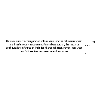
[0083] At S21, resource configuration information for channel
measurement and
interference measurement are received from a base station. The resource
configuration
information includes N channel measurement resources and M interference
measurement
resources, and both N and M are integers greater than or equal to 1.
[0084] Here, optionally, each of the channel measurement resources may
be CSI-RS or
SSB, and each of the interference measurement resources may be CSI-RS.
Specifically,
each of the interference measurement resources may be a Non-Zero Power (NZP)
CSI-RS
14
Date Recue/Date Received 2023-07-25
or a Zero Power (ZP) CSI-RS.
[0085] Through the above operations, embodiments of the present
disclosure configure
channel measurement resources for channel measurement and interference
measurement
resources for interference measurement for the terminal, so that the L -
SINR(s) of the
beam(s) can be measured and reported by the terminal based on the above
measurement
resources, thereby selecting a more suitable beam(s) on the basis of the L1-
SINR(s).
[0086] After performing the S21, the terminal may further measure the
channel
measurement resources and the interference measurement resources according to
the
resource configuration information, and calculate at least one Ll-SINR
according to
measurement of the channel measurement resources and the interference
measurement
resources.
[0087] According to at least one embodiment of the present disclosure,
the terminal
may further receive first QCL configuration information from the base station.
The first
QCL configuration information is used to configure QCL-Type D information of
the
channel measurement resources and QCL-Type D information of the interference
measurement resources. An Ll-SINR may be calculated from measurement of a
channel
measurement resource and an interference measurement resource that have a QCL-
Type
D relationship with each other.
[00881 Here, QCL may refer to quasi-co-address relationship. For
example, in an LTE
system, quasi-co-location of antenna ports may be an assumption about a state
between
antenna ports. If one antenna port is quasi-co-located with the other antenna
port, it means
that the terminal may assume that a large-scale characteristic of a signal
received from one
of the antenna ports (or a radio channel corresponding to the antenna port) is
the same as
a large-scale characteristic of a signal received from another antenna port
(or a radio
channel corresponding to the another antenna port) in whole or in part. That
is, if the
channel characteristics on an antenna port symbol can be derived from another
antenna
port, it can be assumed that the two ports are in QCL, and the channel
estimation result
Date Recue/Date Received 2023-07-25
obtained from one port can be used at the another port. Currently, types such
as QCL-Type
A, QCL-Type B, QCL-Type C, and QCL-Type D are defined for QCL; herein QCL-Type
D is the quasi-co-location relationship of the spatial reception parameters.
According to
other embodiments of the present disclosure, the terminal may further receive
second QCL
configuration information from the base station. The second QCL configuration
information is used to configure QCL-Type D information of the channel
measurement
resources, and an LI-SINR may be calculated from measurement of a channel
measurement resource and an interference measurement resource which is the
same as the
channel measurement resource in terms of spatial filtering or QCL-Type D.
[0089] After at least one Ll-SINR is calculated, the terminal may
report the LI -SINR(s)
and an identifier(s) of a channel measurement resource(s) and/or an
identifier(s) of an
interference measurement resource(s) corresponding to the LI-SINR(s) to the
base station.
Specifically, the Ll-SINR(s) and the identifier(s) of the channel measurement
resource(s)
corresponding to the L 1 -SINR(s) can be reported; or the LI -SINR(s) and the
identifier(s)
of the interference measurement resource(s) corresponding to the L I -SINR(s)
can be
reported; or the LI-SINR(s) and the identifier(s) of the channel measurement
resource(s)
and the identifier(s) of the interference measurement resource(s)
corresponding to the LI-
SINR(s) can be reported. In addition, the L1-SINR(s) reported herein may be
all or part of
the calculated at least one LI-SINR. In the case of reporting part of the
calculated at least
one LI-SINR, the terminal may select part of the calculated at least one LI-
SINR for
reporting in descending order of L I -SINR(s).
[009011 The above measurement configuration method will be further
described by
several specific examples below.
[0091] Example 1: M may be equal to N, and the N channel measurement
resources
and N interference measurement resources may be in one-to-one correspondence
in a
predetermined order.
[0092] In example I, when the terminal calculates at least one Li -SINR
according to
16
Date Recue/Date Received 2023-07-25
measurement of the channel measurement resources and the interference
measurement
resources, a channel measurement resource and an interference measurement
resource
corresponding to each other may be measured in a same receiving direction;
herein for
different channel measurement resources, receiving directions are different.
Each of the at
least one L1-SINR may be calculated according to measurement of the channel
measurement resource and the interference measurement resource corresponding
to each
other in the same receiving direction.
[0093] In the case that the LI-SINR(s) and the identifier(s) of the
channel measurement
resource(s) and/or the identifier(s) of the interference measurement
resource(s)
corresponding to the Ll-SINR(s) are reported to the base station, Y LI-SINRs
may be
selected by the terminal from the at least one L I-SINR, and the Y LI-SINRs
and
identifier(s) of channel measurement resource(s) and/or identifier(s) of
interference
measurement resource(s) corresponding to the Y Li -SINRs may be reported to
the base
station; herein Y is an integer greater than or equal to 1. For example, the
first Y Li -SINRs
can be selected in descending order of Li -SINRs. Here, Y may be a
predetermined value
or a value configured by the base station.
[0094] In example 1, the base station may configure N channel
measurement resources
and N interference measurement resources, and correspond the channel
measurement
resources to interference measurement resources one to one in a certain order
to calculate
the L 1 -SINR(s). Further, the terminal may receive each pair of channel
measurement
resources and interference measurement resources through the same receiving
beam.
[0095] The beneficial effects of the example 1 include at least as
follows: it can be used
for the base station to determine the optimal receiving beam. Especially after
the base
station has certain prior information, and desires that the terminal perform a
more accurate
L1-SINR measurement, so as to determine an optimal receiving beam. For
example, if the
base station already has some measurements (such as Channel Quality Indicator,
CQI,
RSRP, etc.) of the beams and desires to make more accurate pairing on this
basis, the base
station may configure the above channel measurement resources and interference
17
Date Recue/Date Received 2023-07-25
measurement resources for the terminal.
[0096] FIG. 3 illustrates a specific resource configuration scheme of
example 1, in
which the base station configures four Channel Measurement Resources (CMRs)
with
identifiers from CMR 0 to CMR 3, and four Interference Measurement Resources
(IMRs)
with identifiers from IMR 0 to IMR 3 for the terminal. The positional
relationship of the
above resources in time domain is illustrated in FIG. 3. It can be seen that a
CMR and an
IMR with the same identifier have the same position in time domain. The
terminal
determines one-to-one correspondences of CMRs and IMRs according to an order
of
identifiers of CMRs and IMRs. Specifically, CMR 0 corresponds to IMR 0, CMR I
corresponds to IMR 1, CMR 2 corresponds to IMR 2, and CMR 3 corresponds to IMR
3.
Of course, embodiments of the present disclosure may also define the
correspondence
relationship in other ways, as long as the terminal and the base station
determine the
correspondence relationship in the same way. The terminal may adopt different
receiving
beams, such as Beam 0 to Beam 3, to measure the channel measurement resources
and the
interference measurement resources. Herein, the same receiving beam may be
adopted for
a channel measurement resource and an interference measurement resource
corresponding
to the channel measurement resource. Thus, the terminal can calculate the Ll-
SINRs
corresponding four pairs of CMRs and IMRs, which represent LI-SINRs in four
directions
of receiving beams.
[00971 For reporting of L I -SINR, the reporting format I that the
terminal may adopt
includes:
[00981 L I -SINR and the identifier of the channel measurement resource
corresponding
to the L I -SINR.
[0099] L1-SINR and the identifier of the interference measurement
resource
corresponding to the L I-S1NR.
[00100] L1-SINR and the identifier of the channel measurement resource
and the
identifier of the interference measurement resource corresponding to the LI-
SINR.
18
Date Recue/Date Received 2023-07-25
[00101] In addition, the terminal may report the L1-SINR with the
largest value, or
report Y identifiers of the channel measurement resources and Y corresponding
L1-SINRs.
When multiple L I -SINRs are reported, differential reporting format can be
adopted.
[00102] Example 2: the N channel measurement resources may be located
before the M
interference measurement resources in time domain.
[00103] In example 2, when the terminal calculates at least one Ll-SINR
according to
measurement of the channel measurement resources and the interference
measurement
resources, the N channel measurement resources may be measured in different
receiving
directions to obtain a first measurement, which may be received signal
strengths, and X
channel measurement resources may be selected according to the first
measurement. For
example, X receiving beams may be selected in descending order of the received
signal
strengths. M interference measurement resources may be measured in the
receiving
directions corresponding to the X channel measurement resources to obtain a
second
measurement, and each of the at least one LI-SINR may be calculated according
to
measurement of a channel measurement resource and an interference measurement
resource in the same receiving direction.
[00104] In the case that the LI-SINR(s) and the identifier(s) of the
channel measurement
resource(s) and/or the identifier(s) of the interference measurement
resource(s)
corresponding to the L1-SINR(s) are reported to the base station, Z L1-SINRs
may be
selected by the terminal from the at least one LI -SINR, and the Z LI-SINRs
and
identifier(s) of channel measurement resource(s) and identifier(s) of
interference
measurement resources(s) corresponding to the Z Li -SINRs may be reported to
the base
station; herein Z is an integer greater than or equal to 1. For example, the
Ll-SINRs are
sorted in in descending order, and the first Z LI-SINRs can be selected. Here,
Z may be a
predetermined value or a value configured by the base station.
[00105] In example 2, the base station configures N channel measurement
resources and
M interference measurement resources, and the channel measurement resources
and
19
Date Recue/Date Received 2023-07-25
interference the measurement resources can be staggered in a Time Division
Multiplexing
(TDM) manner in time domain. The terminal firstly measures the channel
measurement
resources, determines X receiving beam directions according to measurement of
the
channel measurement resources, and then receives M interference measurement
resources
in the determined X receiving beam directions. Since there are M interference
measurement resources, M L1-SINRs can be calculated.
[00106] The beneficial effects of the second example include at least as
follows: when
determining the multi-user pairing of the Multi-User-Multi-Input-Multi-Output
(MU-
MIN10), for example, the base station may configure the receiving beam
direction of a
CMR corresponding to one of the selected M LI -SINRs to UE1, configure the
receiving
beam direction of an IMR corresponding to the L I-SINR to UE2, and performs
multi-user
pairing for UE1 and UE2, thereby reducing interference between UE1 and UE2.
[00107] FIG. 4 illustrates a specific resource configuration scheme of
example 2, in
which the base station configures four CMRs with identifiers from CMR 0 to CMR
3, and
two IMRs with identifiers from IMR 0 to IMR I for the terminal. The positional
relationship of the above resources in time domain is illustrated in FIG. 4.
It can be seen
that time domain positions of the CMRs are different from those of the IMRs.
The terminal
may adopt different receiving beams, such as Beam 0 to Beam 3, to measure the
channel
measurement resources, respectively. Then, according to the order of RSRP
sizes, a
receiving beam(s) (assuming Beam I) corresponding to the largest X (assuming
one here)
RSRP(s) is/are selected. The interference measurement resources IMR 0 and TMR
I are
received through the receiving beam Beam 1, so that the M LI -SINRs (two LI-
SINRs
here) are calculated by using the measurement of the channel measurement
resources and
the interference measurement resources measured through the receiving beam(s).
[00108] For reporting of an LI-SINR, the reporting format 2 that the
terminal may adopt
includes:
[00109] LI -SINR and the identifier of the channel measurement resource
and the
Date Recue/Date Received 2023-07-25
identifier of the interference measurement resource corresponding to the L1-
SINR.
[00110] In addition, the terminal may report the L I-SINR with the
largest value, or
report Z LI-SINRs and the identifiers of the channel measurement resources
corresponding to the Z L I -SINRs and the identifiers of the interference
measurement
resources corresponding to the Z L I -SINRs. When multiple L I -SINRs are
reported, a
differential reporting format can be adopted.
[00111] Example 3: the M interference measurement resources may include
N first
interference measurement resources and S second interference measurement
resources, the
N channel measurement resources and the N first interference measurement
resource may
be in one-to-one correspondence in a predetermined order, and the N channel
measurement
resources may be located before the S second interference measurement
resources in time
domain.
[00112] In example 3, when the terminal calculates at least one L1-SINR
according to
measurement of the channel measurement resources and the interference
measurement
resources, a channel measurement resource and a first interference measurement
resource
corresponding to the channel measurement resource may be measured in the same
receiving direction; for different channel measurement resources, different
receiving
directions may be adopted. Each of at least one LI-SINR may be calculated
according to
measurement of a channel measurement resource and a first interference
measurement
resource corresponding to channel measurement resource in the same receiving
direction.
P L I -SINRs may be selected from the at least one L I -SINR, and P receiving
directions
corresponding to the P L I -SINRs may be determined; herein P is an integer
greater than
or equal to 1. For example, P L1-SINRs may be selected in descending order of
LI-SINRs.
The S second interference measurement resources may be measured in the P
receiving
directions, and each of the at least one L I-SINR may be calculated according
to
measurement of a channel measurement resource and a second interference
measurement
resource in the same receiving direction.
21
Date Recue/Date Received 2023-07-25
[00113] When the L1-SINR(s) and the identifier(s) of the channel
measurement
resource(s) and/or the identifier(s) of the interference measurement
resource(s)
corresponding to the L 1 -SINR(s) are reported to the base station, L L 1 -
SINRs may be
selected from the at least one L I -SINR by the terminal; the L Ll-SINRs and
an identifiers
of channel measurement resources and identifiers of second interference
measurement
resources corresponding to the L L I -SINRs may be reported to the base
station; herein the
L is an integer greater than or equal to I. For example, the first LLI-SINRs
can be selected
in descending order of LI-SINRs. Here, L may be a predetermined value or a
value
configured by the base station..
[00114] In example 3, the base station configures N channel measurement
resources, N
first interference measurement resources and S second interference measurement
resources; herein the N channel measurement resources and the N first
interference
measurement resources are in one-to-one correspondence in a certain order, and
the
channel measurement resources and the second interference measurement
resources need
to be staggered in a I'DM manner in time domain. The terminal performs
measurement
based on the N channel measurement resources and the N first interference
measurement
resources, calculates N first L1-SINRs, each according to a respective one of
the N channel
measurement resources and a respective one of the N first first interference
measurement
resources corresponding to each other, selects P first LI-SINRs from the N
first LI-SINRs,
determines P receiving directions corresponding to the P first LI-SINRs,
performs
measurement on the S second interference measurement resources by using the P
receiving
directions, and calculates S Ll -SINRs, each according to the measurement of a
channel
measurement resource and a second interference measurement resource in the
same
receiving direction.
[00115] FIG. 5 illustrates a specific resource configuration scheme of
example 3, in
which the base station configures four CMRs with identifiers from CMR 0 to CMR
3, and
six IMRs with identifiers from IMR 0 to IMR 5 for the terminal. The positional
relationship of the above resources in time domain is illustrated in FIG. 5.
It can be seen
that time domain positions of the channel measurement resources and IMR 4-IMR
5 are
22
Date Recue/Date Received 2023-07-25
different. The terminal may adopt different receiving beams, such as Beam 0 to
Beam 3,
to measure the CMR 0-CMR 3 and IMR 0-IMR 3, respectively. The same receiving
beam
may be adopted for a channel measurement resource and an interference
measurement
resource corresponding to the channel measurement resource. Thus, the terminal
can
calculate the LI-SINRs corresponding to four pairs of CMRs and IMRs, which
represent
LI-SINRs in four directions of receiving beams. Then, a receiving beam(s)
(assuming
Beam 1) corresponding to the largest P (assuming one here) RSRP(s) is/are
selected in
descending order of L1-SINRs. The interference measurement resources IMR 4 and
IMR
are received through the receiving beam Beam I, so that the 2 L I -SITNRs can
be
calculated by using the measurement of the channel measurement resources CMR 1
and
the interference measurement resources IMR 4 and IMR 5 measured through the
receiving
beam.
[00116] For reporting of the L I -SINR(s), the reporting format 3 that
the terminal may
adopt is similar to the reporting format 2 of example 2.
[00117] FIG. 6 provides a flowchart of a measurement configuration
method applied to
a base station side according to embodiments of the present disclosure,
including the
following operations.
[00118] At S61, resource configuration information for channel
measurement and
interference measurement is transmitted to a terminal. The resource
configuration
information includes N channel measurement resources and M interference
measurement
resources, and both N and M are integers greater than or equal to 1.
[00119] Here, Optionally, each of the channel measurement resources may
be CSI-RS
or SSB, and each of the interference measurement resources may be CSI-RS.
Specifically,
each of the interference measurement resource may be a Non-Zero Power (NZP)
CSI-RS
or a Zero Power (ZP) CSI-RS.
[00120] Through the above operations, the base station of embodiments of
the present
disclosure configures channel measurement resources for channel measurement
and
23
Date Recue/Date Received 2023-07-25
interference measurement resources for interference measurement for the
terminal, so that
the L 1 -SINR(s) of the beam(s) can be measured and reported by the terminal
based on the
above measurement resources, thereby selecting a more suitable beam(s) on the
basis of
the L 1 -SINR(s).
[00121] In the embodiments of the present disclosure, after the
operation 61 is performed,
the base station may further receive a L1-SINR(s) and an identifier(s) of a
channel
measurement resource(s) and/or an identifier(s) of an interference measurement
resource(s)
corresponding to the L1-SINR(s) reported by the terminal.
[00122] Furthermore, the base station may configure the receiving
beam(s) for the
terminal based on the L I -SINR(s) and the identifier(s) of the channel
measurement
resource(s) and/or the identifier(s) of the interference measurement
resource(s)
corresponding to the L 1 -SINR(s) reported by the terminal, for example,
configure the
receiving beam received by the terminal corresponding to the maximum L 1-SINR
as the
receiving beam of the terminal.
[00123] According to at least one embodiment of the present disclosure,
the base station
may further transmit first QCL configuration information to the terminal. The
first QCL
configuration information is used to configure QCL-Type D information of the
channel
measurement resources and QCL-Type D information of the interference
measurement
resources. Herein an LI-SINR may be calculated from measurement of a channel
measurement resource and an interference measurement resource that have a QCL-
Type
D relationship with each other.
[00124] According to other embodiments of the present disclosure, the
base station may
further transmit second QCL configuration information to the terminal. The
second QCL
configuration information is used to configure QCL-Type D information of the
channel
measurement resources, and an LI -SINR may be calculated from measurement of a
channel measurement resource and an interference measurement resource which is
the
same as the channel measurement resource in terms of spatial filtering or QCL-
Type D.
24
Date Recue/Date Received 2023-07-25
[00125] Optionally, corresponding to the above-mentioned example 1, M
may be equal
to N. and the N channel measurement resources and N interference measurement
resources
may be in one-to-one correspondence in a predetermined order.
[00126] Optionally, corresponding to the above-mentioned example 2, the
N channel
measurement resources may be located before the M interference measurement
resources
in time domain.
[00127] Optionally, corresponding to the above-mentioned example 3, the
M
interference measurement resources may include N first interference
measurement
resources and S second interference measurement resources, the N channel
measurement
resources and the N first interference measurement resource may be in one-to-
one
correspondence in a predetermined order, and the N channel measurement
resources may
be located before the S second interference measurement resources in time
domain.
[00128] Optionally, when the base station performs multi-user pairing
for MU-MIMO,
based on L1-SINRs and identifiers of channel measurement resources and/or
identifiers
of interference measurement resources corresponding to the LI-SINRs reported
by the
terminal, a receiving beam direction of a channel measurement resource
corresponding to
a same L 1 -SINR in the reported LI-SINRs is configured to the terminal, and a
receiving
beam direction of an interference measurement resource corresponding to the LI-
SINR is
configured to another terminal. Herein the another terminal and the terminal
belong to the
same multi-user pairing.
[00129] Based on the above methods, embodiment of the present disclosure
further
provides a device for implementing the above methods.
[00130] Referring to FIG. 7, embodiments of the present disclosure
provide a terminal
70, including a receiving module 70, configured to receive resource
configuration
information for channel measurement and interference measurement from a base
station.
The resource configuration information includes N channel measurement
resources and
M interference measurement resources, and both N and M are integers greater
than or
Date Recue/Date Received 2023-07-25
equal to 1.
[00131] Optionally, the terminal further includes a measuring unit,
configured to
measure the channel measurement resources and the interference measurement
resources
according to the resource configuration information, and calculate at least
one L 1 -SINR
according to measurement of the channel measurement resources and the
interference
measurement resources.
[00132] Optionally, the ten-ninal further includes a receiving unit,
configured to receive
QCL configuration information from the base station. The QCL configuration
information
is used to configure a channel measurement resource and an interference
measurement
resource that have a QCL-Type D relationship with each other.
[00133] Herein the LI-SINR may be calculated from measurement of a
channel
measurement resource and an interference measurement resource that have a QCL-
Type
D relationship with each other.
[00134] Optionally, the terminal further includes a reporting unit,
configured to report
the LI-S1NR and an identifier of a channel measurement resource and/or an
identifier of
an interference measurement resource corresponding to the Ll-SINR to the base
station.
[00135] Optionally, M may be equal to N, and the N channel measurement
resources
and N interference measurement resources may be in one-to-one correspondence
in a
predetermined order.
[00136] Optionally, the measuring unit is further configured to measure
a channel
measurement resource and an interference measurement resource corresponding to
each
other in a same receiving direction, receiving directions for different
channel measurement
resources being different, and calculate each of at least one L1-SINR
according to
measurement of a channel measurement resource and an interference measurement
resource corresponding to each other in the same receiving direction.
[00137] Optionally, the reporting unit is further configured to select Y
LI-SINRs from
26
Date Recue/Date Received 2023-07-25
the at least one L1-SINR, and report the Y L1-SINRs and identifiers of channel
measurement resources and/or identifiers of interference measurement resources
corresponding to the Y L I -SINRs to the base station; herein Y is an integer
greater than or
equal to 1 .
[00138] Optionally, the N channel measurement resources may be located
before the M
interference measurement resources in time domain.
[00139] Optionally, the measuring unit is further configured to measure
the N channel
measurement resources in difference receiving directions; select X channel
measurement
resources according to a first measurement; measure the M interference
measurement
resources in the receiving directions corresponding to the X channel
measurement
resources to obtain a second measurement, and calculate each of the at least
one LI -SINR
according to measurement of a channel measurement resource and an interference
measurement resource in the same receiving direction.
[00140] Optionally, the reporting unit is further configured to select Z
L1-SINRs from
the at least one L I-SINR; report the Z L 1 -S[NRs and identifiers of channel
measurement
resources and identifiers of interference measurement resources corresponding
to the Z
Li-SINRs to the base station; herein the Z is an integer greater than or equal
to 1.
[00141] Optionally, the M interference measurement resources may include
N first
interference measurement resources and S second interference measurement
resources, the
N channel measurement resources and the N first interference measurement
resource may
be in one-to-one correspondence in a predetermined order, and the N channel
measurement
resources may be located before the S second interference measurement
resources in time
domain.
[00142] Optionally, the measuring unit is further configured to measure
a channel
measurement resource and a first interference measurement resource
corresponding to
each other in a same receiving direction, receiving directions for different
channel
measurement resources being different; calculate each of at least one L I-SINR
according
27
Date Recue/Date Received 2023-07-25
to measurement of a channel measurement resource and an interference
measurement
resource corresponding to each other in the same receiving direction; select P
L1-SINRs
from the at least one Ll-SINR, and determine P receiving directions
corresponding to the
P L 1 -SINRs, P being an integer greater than or equal to 1; measure the S
second
interference measurement resources in the P receiving directions, and
calculate each of the
at least one LI-SINR according to measurement of a channel measurement
resource and
a second interference measurement resource in the same receiving direction.
[00143] Optionally, the reporting unit is further configured to select L
LI-SINRs from
the at least one LI-SINR; report the L Ll-SINRs and identifiers of a channel
measurement
resources and an identifiers of second interference measurement resources
corresponding
to the L LI-SINRs to the base station; herein the L is an integer greater than
or equal to 1.
[00144] Referring to FIG. 8, embodiments of the present disclosure
provide another
structure structural diagram of a terminal, which includes a processor 801, a
transceiver
802, a memory 803, a user inteiface 804 and a bus interface.
[00145] In the embodiment of the present disclosure, the terminal
further includes
instructions stored in the memory 803 and executable by the processor 801. The
following
operations can be implemented when the instructions are executed by the
processor 801.
[00146] Resource configuration information for channel measurement and
interference
measurement are received from a base station. Herein, the resource
configuration
information includes N channel measurement resources and M interference
measurement
resources, and both N and M are integers greater than or equal to 1.
[00147] In FIG. 8, a bus architecture may include any number of
interconnected buses
and bridges, which are linked together by one or more processors represented
by the
processor 801 and various circuits of memories represented by the memory 803.
The bus
architecture may also link together a variety of other circuitry such as
peripheral
equipment, voltage regulator and power management circuit etc., which are well
known
in the art and therefore will not be further described herein. The bus
interface provides the
28
Date Recue/Date Received 2023-07-25
interface. The transceiver 802 may include multiple elements, that is, the
transceiver 802
may include a transmitter and a receiver, which provides a unit for
communicating with
various other devices over a transmission medium. For different user
equipment, the user
interface 804 may also be an interface capable of externally and inwardly
connecting the
desired device, the connected device including but not limited to a keypad, a
display, a
speaker, a microphone, a joystick, and the like.
[00148] The processor 801 is responsible for managing the bus
architecture and general
processing and the memory 803 may store data used by the processor 801 in
performing
operations.
[00149] Optionally, when the program is executed by the processor 803,
the following
operation may also be implemented.
[00150] The channel measurement resources and the interference
measurement
resources may be measured according to the resource configuration information,
and at
least one L1-SINR may be calculated according to measurement of the channel
measurement resources and the interference measurement resources.
[00151] Optionally, when the program is executed by the processor 803,
the following
operation may also be implemented.
[00152] QCL configuration information is received from the base station.
The QCL
configuration infonnation is used to configure a channel measurement resource
and an
interference measurement resource that have a QCL-Type D relationship with
each other.
[00153] Herein the LI-SINR may be calculated from measurement of a
channel
measurement resource and an interference measurement resource that have a QCL-
Type
D relationship with each other.
[00154] Optionally, when the program is executed by the processor 803,
the following
operation may also be implemented.
29
Date Recue/Date Received 2023-07-25
[00155] The L1-SINR and an identifier of a channel measurement resource
and/or an
identifier of an interference measurement resource corresponding to the L1-
SINR may be
reported to the base station.
[00156] Optionally, M may be equal to N, and the N channel measurement
resources
and N interference measurement resources may be in one-to-one correspondence
in a
predetermined order.
[00157] Optionally, when the program is executed by the processor 803,
the following
operations may also be implemented.
[00158] A channel measurement resource and an interference measurement
resource
corresponding to each other may be measured in a same receiving direction;
herein
receiving directions for different channel measurement resources are
different.
[00159] Each of the at least one L 1-SINR may be calculated according to
measurement
of a channel measurement resource and an interference measurement resource
corresponding to each other in the same receiving direction.
[00160] Optionally, when the program is executed by the processor 803,
the following
operations may also be implemented.
[00161] Y Ll-SINRs may be selected from the at least one L1-SINR, and
the Y Ll-
SINRs and identifiers of channel measurement resources and/or identifiers of
interference
measurement resources corresponding to the Y LI-SINRs may be reported to the
base
station; herein Y is an integer greater than or equal to I.
[00162] Optionally, the N channel measurement resources may be located
before the M
interference measurement resources in time domain.
[00163] Optionally, when the program is executed by the processor 803,
the following
operations may also be implemented.
[00164] The N channel measurement resources may be measured in different
receiving
Date Recue/Date Received 2023-07-25
directions, and X channel measurement resources may be selected according to a
first
measurement.
[00165] The M interference measurement resources may be measured in the
receiving
directions corresponding to the X channel measurement resources to obtain a
second
measurement.
[00166] Each of the at least one LI-SINR may be calculated according to
measurement
of a channel measurement resource and an interference measurement resource in
the same
receiving direction.
[00167] Optionally, when the program is executed by the processor 803,
the following
operations may also be implemented.
[00168] Z LI-SINRs may be selected from the at least one LI-SINR; the Z
L1-SINRs
and identifiers of channel measurement resources and identifiers of
interference
measurement resources corresponding to the Z L1-SINRs may be reported to the
base
station; herein the Z is an integer greater than or equal to 1.
[00169] Optionally, the M interference measurement resources may include
N first
interference measurement resources and S second interference measurement
resources, the
N channel measurement resources and the N first interference measurement
resource may
be in one-to-one correspondence in a predetermined order, and the N channel
measurement
resources may be located before the S second interference measurement
resources in time
domain.
[00170] Optionally, when the program is executed by the processor 803,
the following
operations may also be implemented.
[00171] A channel measurement resource and a first interference
measurement resource
corresponding to each other may be measured in a same receiving direction.
Receiving
directions for different channel measurement resources are different.
31
Date Recue/Date Received 2023-07-25
[00172] At least one L1-SINR may be calculated according to measurement
of the
channel measurement resource and the first interference measurement resource
corresponding to each other in the same receiving direction.
[00173] P L I -SINRs may be selected from the at least one L 1 -SINR,
and P receiving
directions corresponding to the P L I -SINRs may be determined; herein P is an
integer
greater than or equal to 1.
[00174] The S second interference measurement resources may be measured
in the P
receiving directions.
[00175] The at least one L1-SINR may be calculated, each according to
measurement of
a channel measurement resource and a second interference measurement resource
in the
same receiving direction.
[00176] Optionally, when the program is executed by the processor 803,
the following
operations may also be implemented.
[00177] L LI -SINRs may be selected from the at least one Ll -SINR; the
L Ll-SINRs
and an identifier(s) of a channel measurement resource(s) and an identifier(s)
of a second
interference measurement resource(s) corresponding to the L Ll-SINRs may be
reported
to the base station; herein the L is an integer greater than or equal to 1.
[00178] Referring to FIG. 9, embodiments of the present disclosure
provide a base
station 90, including a transmitting module 91, configured to transmit
resource
configuration information for channel measurement and interference measurement
to a
terminal. The resource configuration information includes N channel
measurement
resources and M interference measurement resources, and both N and M are
integers
greater than or equal to 1.
[00179] Optionally, the base station further includes a receiving
module, configured to
receive LI-SINR and an identifier of a channel measurement resource amd/or an
identifier
of an interference measurement resource corresponding to the LI-SINR reported
by the
32
Date Recue/Date Received 2023-07-25
terminal.
[00180] Optionally, the transmitting module is further configured to
transmit QCL
configuration information to terminal; herein the QCL configuration
information is used
to configure a channel measurement resource and an interference measurement
resource
that have a QCL-Type D relationship with each other.
[00181] Herein the LI-SINR may be calculated from measurement of a
channel
measurement resource and an interference measurement resource that have a QCL-
Type
D relationship with each other.
[00182] Optionally, M may be equal to N, and the N channel measurement
resources
and N interference measurement resources may be in one-to-one correspondence
in a
predeteimined order.
[00183] Optionally, the N channel measurement resources may be located
before the M
interference measurement resources in time domain.
[00184] Optionally, the M interference measurement resources may include
N first
interference measurement resources and S second interference measurement
resources, the
N channel measurement resources and the N first interference measurement
resource may
be in one-to-one correspondence in a predetermined order, and the N channel
measurement
resources may be located before the S second interference measurement
resources in time
domain.
[00185] Optionally, the base station further includes a configuration
module, configured
to when performing multi-user pairing for MU-MIMO, configure, based on the L1-
SINRs
and identifiers of channel measurement resources and/or identifiers of
interference
measurement resources corresponding to the LI-SINRs reported by the terminal,
a
receiving beam direction of a channel measurement resource corresponding to
the same
L I -SINR in the reported L 1 -SINRs to the terminal, and configure a
receiving beam
direction of an interference measurement resource corresponding to the L 1 -
SINR to
33
Date Recue/Date Received 2023-07-25
another terminal. Herein, the another terminal and the terminal belong to the
same multi-
user pairing.
[00186] Referring to FIG. 10, embodiments of the present disclosure
provide another
structure structural diagram of a base station 1000, which includes a
processor 1001, a
transceiver 1002, a memory 1003 and a bus interface.
[00187] In the embodiment of the present disclosure, the base station
1000 further
includes instructions stored in the memory 1003 and executable by the
processor 1001.
The following operations can be implemented when the instructions are executed
by the
processor 1001.
[00188] Resource configuration information for channel measurement and
interference
measurement is transmitted to a terminal. The resource configuration
information includes
N channel measurement resources and M interference measurement resources, and
both
N and M are integers greater than or equal to 1.
[00189] In FIG. 10, a bus architecture may include any number of
interconnected buses
and bridges, which are linked together by one or more processors represented
by the
processor 1001 and various circuits of memories represented by the memory
1003. The
bus architecture may also link together a variety of other circuitry such as
peripheral
equipment, voltage regulator and power management circuit etc., which are well
known
in the art and therefore will not be further described herein. The bus
interface provides the
interface. The transceiver 1002 may include multiple elements, that is, the
transceiver
1002 may include a transmitter and a receiver, which provides a unit for
communicating
with various other devices over a transmission medium.
[00190] The processor 1001 is responsible for managing the bus
architecture and general
processing and the memory 1003 may store data used by the processor 1001 in
performing
operations.
[00191] Optionally, when the program is executed by the processor 1001,
the following
34
Date Recue/Date Received 2023-07-25
operations may also be implemented.
[00192] L1-SINR and an identifier of a channel measurement resource
and/or an
identifier of an interference measurement resource corresponding to the Li -
SINR reported
by the terminal may be received.
[00193] Optionally, when the program is executed by the processor 1001,
the following
operations may also be implemented.
[00194] QCL configuration information is transmitted to the terminal.
The QCL
configuration information is used to configure a channel measurement resource
and an
interference measurement resource that have a QCL-Type D relationship with
each other.
[00195] An Ll-SINR may be calculated from measurement of a channel
measurement
resource and an interference measurement resource that have a QCL-Type D
relationship
with each other.
[00196] Optionally, M may be equal to N, and the N channel measurement
resources
and N interference measurement resources may be in one-to-one correspondence
in a
predeten-nined order.
[00197] Optionally, the N channel measurement resources may be located
before the M
interference measurement resources in time domain.
[00198] Optionally, the M interference measurement resources may include
N first
interference measurement resources and S second interference measurement
resources, the
N channel measurement resources and the N first interference measurement
resource may
be in one-to-one correspondence in a predetermined order, and the N channel
measurement
resources may be located before the S second interference measurement
resources in time
domain.
[00199] Optionally, when the program is executed by the processor 1001,
the following
operations may also be implemented.
Date Recue/Date Received 2023-07-25
[00200] When multi-user pairing for MU-MIMO is being performed, based on
Ll-
SINRs and identifiers of channel measurement resources and/or identifiers of
interference
measurement resources corresponding to the L I -SINRs reported by the
terminal, a
receiving beam direction of a channel measurement resource corresponding to a
same L I -
SINR in the reported LI-SINRs is configured to the ten-ninal, and a receiving
beam
direction of an interference measurement resource corresponding to the L1-SINR
is
configured to another terminal; herein the another terminal and the terminal
belong to the
same multi-user pairing.
[00201] Those skilled in the art will appreciate that the various
example units and
algorithm steps described in connection with the embodiments disclosed herein
can be
implemented in electronic hardware or a combination of computer software and
electronic
hardware. Whether these functions are performed in hardware or software form
depends
on specific applications and design constraints of the technical scheme. Those
skilled may
use different methods for each specific application to implement the described
functions
but such implementation should not be considered beyond the scope of the
present
disclosure.
[00202] Those skilled in the art will clearly appreciate that for
convenience and
conciseness of description, the specific operating processes of the above-
mentioned
systems, devices and units may refer to the corresponding processes in the
aforementioned
method embodiments and will not be repeated herein.
[00203] In the embodiments provided herein it should be understood that
the disclosed
devices and methods may be implemented in other ways. For example, the above-
mentioned embodiments of the device are only schematic. For example, the
division of
the unit is only a logical functional division, and in practice, there may be
another division
manner. For example, multiple units or components may be combined or
integrated into
another system, or some features may be ignored or not performed. On the other
hand, the
coupling or direct coupling or communication connection between each other
illustrated
or discussed may be indirect coupling or communication connection through some
36
Date Recue/Date Received 2023-07-25
interface, device or unit, and may be electrical, mechanical or other forms.
[00204] The units illustrated as separate elements may or may not be
physically
separated, and the elements displayed as units may or may not be physical
units, i.e., they
may be located in one place, or may be distributed over multiple network
units. Some or
all of the units may be selected according to actual needs to achieve the
objectives of the
embodiments of the present disclosure.
[00205] In addition, the functional units in various embodiments of the
present
disclosure may be integrated in one processing unit, or each unit may exist
physically
individually, or two or more units may be integrated in one unit.
[00206] The functions may be stored in a computer-readable storage
medium if
implemented in form of software functional units and sold or used as stand-
alone products.
Based on such an understanding, the essence of the technical solutions of the
present
disclosure, or the part that contributes to the related technologies, or part
of the technical
solutions can be embodied in the form of a software product stored in a
storage medium
including several instructions, which can be executed by a computer device
(which may
be a personal computer, a server, or a base station, etc.) to implement all or
part of the
operations of the measurement configuration method described in the various
embodiments of the present disclosure. The foregoing storage medium includes a
Universal Serial Bus (USB) flash drive, a removable hard disk, a Read-Only
Memory
(ROM), a Random Access Memory (RAM), a magnetic disk, an optical disk, or any
other
medium that can store program code.
[00207] The foregoing description is merely specific embodiments of the
present
disclosure, but the scope of protection of the present disclosure is not
limited hereto. Any
variation or replacement readily contemplated by those skilled in the art
within the scope
of the present disclosure should be included within the scope of protection of
the present
disclosure. Therefore, the scope of protection of the present disclosure shall
be limited by
the scope of protection of the claims.
37
Date Recue/Date Received 2023-07-25