Note: Descriptions are shown in the official language in which they were submitted.
"A chair with pivoting seat and backrest"
****
DESCRIPTION
Field of the invention
The present invention relates to a chair with pivoting seat
and backrest.
More precisely, the invention relates to a chair wherein the
seat and the backrest are hinged about respective transverse
axes and wherein the backwards inclination movement of the
backrest is coordinated with an upwards pivoting movement of the
rear part of the seat.
Prior art
In the present state of the art many chairs provided with a
mechanism which allows synchronization of the backwards
inclination movement of the backrest and the pivoting movement
of the seat in order to make the chair comfortable and ergonomic
are known.
In the present state of the art chairs provided with so-
called weight-activated mechanisms are also known, where the
backwards pivoting movement of the backrest results in a
simultaneous raising movement of the seat, so that the
resistance to the backwards inclination of the backrest is
related to the weight of the user.
The mechanisms which are able to provide a synchronized
pivoting movement of the seat and the backrest are usually
complex, bulky and costly and require lever mechanisms for the
relative synchronization of the seat and backrest movements.
- 1 -
CA 3151597 2022-03-11
Generally, the mechanisms of the known type require elastic
elements in order to provide a reaction force which opposes the
backwards thrust imparted to the backrest by the user's back.
The mechanisms for synchronized pivoting of the seat and
backrest involve a substantial increase in the complexity of the
chair and, owing to their volume, result in constraints which
make it difficult to achieve a simple and linear design.
Object and summary of the invention
The object of the present invention is to provide a chair
with pivoting seat and backrest which overcomes the problems of
the prior art.
More precisely, the object of the invention is to provide a
chair with a weight-activated pivoting mechanism, which has an
extremely simple structure and does not have bulky dimensions
which limit the freedom of the designer.
According to the present invention, these objects are
achieved by a chair having the features forming the subject of
claim 1.
Optional features of the chair according to the invention
form the subject of the dependent claims.
As will become clear from the description below, the chair
according to the present invention performs a backward pivoting
movement of the backrest and a simultaneous raising movement of
the rear part of the seat so that the reaction to the backwards
inclination movement of the backrest is proportional to the
weight of the user. The chair according to the present invention
is entirely without elastic elements for providing a reaction
force in response to the backwards inclination movement and the
return movement into the rest configuration. As will become
clear below, the chair according to the present invention makes
- 2 -
CA 3151597 2022-03-11
use of the elastic deformation of the frame in order to allow a
relative movement of the hinging axes of the seat and the
backrest during the movement from the rest position into the
backwards inclined position and vice versa.
Brief description of the drawings
The present invention will now be described in detail with
reference to the accompanying drawings provided purely by way of
a non-limiting example in which:
- Figure 1 is a perspective view of a chair according to
the invention;
- Figure 2 is an exploded perspective view of the chair
shown in Figure 1;
- Figure 3 is a side view of the chair according to
Figure 1 in the rest configuration;
- Figure 4 is a side view showing the chair according to
Figure 2 in the position where it is fully inclined backwards;
- Figure 5 is a schematic side view illustrating the
movements of the seat, backrest and frame in the rest
configuration and in the fully inclined backwards configuration;
Figure 6 is a cross-section on a larger scale along the
line VI-VI of Figure 1;
- Figure 7 is a cross-section along the line VII-VII of
Figure 1; and
- Figures 8 and 9 are cross-sections on a larger scale
along the line VIII-VIII of Figure 1, in the rest configuration
and in the fully inclined backwards configuration, respectively.
Detailed description
- 3 -
CA 3151597 2022-03-11
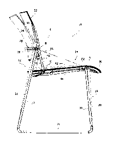
With reference to Figures 1-5, 10 denotes a chair with
pivoting seat and backrest. The chair 10 comprises a frame 12, a
seat 14 and a backrest 16.
The frame 12 may be formed by a plurality of metal bars
consisting of solid or tubular rods which are folded and fixed
together. In one possible embodiment the frame 12 comprises two
frame side sections 18, each of which comprises a front leg 20,
a rear leg 22 and a bottom element 24 which connects together
the bottom ends of the front leg 20 and the rear leg 22.
With reference in particular to Figure 2, the two frame
sections 18 are connected together by a front transverse element
26 and by a rear transverse element 28. The front transverse
element 26 connects together the top ends of the two front legs
20 and the rear transverse element 28 connects together the top
ends of the two rear legs 22. The rear transverse element 28 is
situated at a greater height than the height of the front
transverse element 26.
The front transverse element 26 comprises two side sections
30 and a central section 32. The two side sections 30 are
aligned with each other along a horizontal transverse line which
defines a first hinging axis A.
The rear transverse element 28 comprises two straight side
sections 34 joined together by a curved central section 36. The
two side sections 34 of the rear transverse element 28 are
aligned with each other along a horizontal transverse line which
defines a second hinging axis B. The second hinging axis B is
parallel to the first hinging axis A and is displaced backwards
and upwards with respect to the first hinging axis A.
With reference to Figures 1-5, the seat 14 has a front
section 38 and a rear section 40. The front section 38 of the
seat 14 is hinged with the frame 12 about the first hinging axis
- 4 -
CA 3151597 2022-03-11
A. In one possible embodiment, the seat 14 may be formed by an
upper panel 42 and by a lower panel 44 which are fixed together
by means of screws 46. The upper panel 42 and the lower panel 44
of the seat 14 are situated on opposite sides of the front
transverse element 26 and enclose the front transverse element
26 inside the front section 38 of the seat 14. At least one of
the panels 40, 42 may be provided with hinging seats 48 (Figure
2) which cooperate with the respective side sections 30 of the
front transverse element 26 so as to form a hinged connection
between the front section 38 of the seat 14 and the front
transverse element 26 which allows the seat 14 to pivot about
the first hinging axis A. Obviously it is understood that the
hinged connection between the front section 38 of the seat 14
and front transverse element 26 of the frame 12 may be realized
in any other way.
With reference to Figures 1-6, the backrest 16 comprises a
backrest support 50 and a backrest panel 52 which is fixed to
the backrest support 50. The backrest panel 52 may be made of
moulded plastic material and may have a curved surface for
supporting the user's back. The curved central section 36 of the
rear transverse element 28 extends behind the backrest panel 52.
The backrest support 50 may be formed by folded metal
elements which are substantially U-shaped. With reference in
particular to Figure 2, the backrest support 50 may comprise two
uprights 54 which are parallel to each other and to which the
backrest panel 52 is fixed. The two uprights 54 of the backrest
support 50 may have top ends which are inserted and fixed inside
respective seats 56 of the backrest panel 52. The top ends of
the uprights 54 may be inserted inside the seats 56 with slight
interference.
- 5 -
CA 3151597 2022-03-11
With reference in particular to Figure 2, the two uprights
54 of the backrest support 50 are joined together by a bottom
transverse element 58 having two straight side sections 60 which
are joined together by a curved central section 62. The two
straight side sections 60 are aligned with each other along a
horizontal transverse line which defines a third hinging axis C.
The backrest support 50 may comprise two stop elements 64 which
may be formed by two metal plates which are fixed to the
respective straight side sections 60 of the bottom transverse
element 58.
The backrest 16 is hinged with the rear transverse element
28 of the frame 12 about the second hinging axis B. With
reference to Figure 6, the hinged connection between the
backrest 16 and the rear transverse element 28 may be realized
by means of a pair of hinging plates 66 having respective
circular seats 68 which engage rotatably with respective
straight side sections 34 of the rear transverse element 28.
Each of the two hinging plates 66 may be fixed to a respective
upright 54 of the backrest support 50 by means of screws 70.
The backrest 16 is also hinged with the rear section 40 of
the seat 14 about the third hinging axis C. In one possible
embodiment, the hinged connection between the backrest 16 and
the rear section 40 of the seat 14 may be realized by enclosing
the straight side sections 60 of the bottom transverse element
58 of the backrest support 50 between the upper panel 42 and the
lower panel 44 of the seat 14 and by engaging these straight
sections 60 by means of hinging seats 72 formed in at least one
of the panels 42, 44.
The third hinging axis C which hingeably connects the
backrest 16 to the rear section 40 of the seat 14 is situated
lower and slightly further forwards in relation to the second
- 6 -
CA 3151597 2022-03-11
hinging axis B. The third hinging axis C is situated displaced
backwards with respect to the first hinging axis A. In the rest
configuration shown in Figure 3, the third hinging axis C may be
lower than the first hinging axis A.
With reference to Figure 7, the curved central section 62 of
the bottom transverse element 58 of the backrest support 50 is
housed inside a chamber defined between the upper panel 42 and
the lower panel 44 of the seat 14. In the rest position of the
chair, the curved central section 62 rests against the upper
panel 42 of the seat 14 and forms an end-of-travel stop which
prevents forwards pivoting of the backrest 16 with respect to
the rest position.
When a user applies a backwards thrusting force onto the
backrest 16, the backrest 16 pivots backwards about the second
hinging axis B.
The backwards pivoting of the backrest 16
causes a forwards and upwards movement of the bottom transverse
element 58 of the backrest support 50.
Figure 5 shows by
continuous solid lines the chair in the rest configuration and
by broken lines the configuration of the chair in the condition
where the backrest 16 is fully inclined backwards. The backwards
inclination of the backrest 16 displaces the third hinging axis
C forwards and upwards with respect to the rest configuration.
Therefore, the rear section 40 of the seat 14 moves upwards with
respect to the rest configuration and the seat 14 pivots about
the first hinging axis A.
As shown in Figures 3, 4 and 5, in the rest configuration
the distance between the first hinging axis A and the second
hinging axis B has a first value Dl.
The upwards and forwards
movement of the second rotation axis C during the backwards
pivoting movement of the backrest 16 results in a backwards
displacement of the second hinging axis B and a forwards
- 7 -
CA 3151597 2022-03-11
displacement of the first hinging axis A with respect to the
rest configuration. In the configuration where the backrest 16
is fully inclined backwards, the distance between the first
hinging axis A and the second hinging axis B has a second value
D2 greater than the first value Dl.
The increase in the distance between the first and second
hinging axes A, B during the transition from the rest position
into the backwards inclined position is possible owing to an
elastic deformation of the frame 12. In particular, the top ends
of the two front legs 20 are elastically deformed forwards so as
to allow forwards displacement of the first hinging axis A and
the top ends of the rear legs 22 are elastically deformed
backwards so as to allow the backwards displacement of the
second hinging axis B. When no more backwards thrust is applied
to the backrest 16, the frame 12 returns into the undeformed
rest configuration and the backrest 16 and the seat 14 return
into the rest position.
The raising, during the backwards inclination of the
backrest 16, of the rear section 40 of the seat 14 is such that
the reaction to the backwards inclination of the backrest 16 is
proportional to the user's weight, thus resulting in a pivoting
mechanism of the seat and backrest which is of the weight-
activated type, namely one where the reaction to the backwards
inclination increases as the weight of the user increases.
With reference to Figures 8 and 9, the stop elements 64
fixed to the bottom transverse element 58 of the backrest
support 50 move between the upper panel 42 and the lower panel
44 of the seat 14 during the backwards inclination movement of
the backrest between the rest position (Figure 8) and the fully
inclined backwards position (Figure 9).
In the configuration
shown in Figure 9, the stop elements 64 come into contact with
- 8 -
CA 3151597 2022-03-11
the upper panel 42 of the seat 14. In this condition, the stop
elements 64 prevent a further backwards inclination movement of
the backrest support 50 and therefore form an end-of-travel stop
which defines the position of maximum backwards inclination of
the backrest 16.
The chair according to the present invention provides a high
degree of comfort owing to the synchronized movement of the
backrest and the seat during the backwards inclination of the
backrest. In particular, the upwards movement of the rear
portion of the seat during the backwards inclination of the
backrest prevents the backrest from sliding upwards with respect
to the user's back during the backwards inclination of the
backrest, which would result in an unpleasant sensation due to
the sliding contact with the user's clothes. With the chair
according to the present invention it is possible to obtain a
weight-activated action in a very simple manner and without
large dimensional volumes which would limit the designer's
freedom when choosing the chair design. The chair according to
the present invention does not comprise any elastic elements
since the return movement of the backrest and the seat into the
rest position when there is no longer any backwards thrust
applied by the user's back is achieved by the intrinsic
elasticity of the frame 12.
In possible embodiments, by adopting different proportions
of the frame and the other components it is possible to provide
an easy chair with the same operating and ergonomic
characteristics.
Obviously, without altering the principle of the invention,
the embodiments and the constructional details may be greatly
varied with respect to that described and illustrated, without
- 9 -
CA 3151597 2022-03-11
thereby departing from the scope of the invention as defined in
the accompanying claims.
- 10 -
CA 3151597 2022-03-11