Note: Descriptions are shown in the official language in which they were submitted.
PSTAD024US /11.03.2022 1 --- English application
text.doc
Rail vehicle with dilation profile, method of manufacturing a
rail vehicle and dilation profile
The present invention relates to a rail vehicle having a
dilation profile, a method of manufacturing a rail vehicle, and
a dilation profile.
A rail vehicle according to the prior art has an intermediate
floor which is connected to the structure of the car body by
means of connecting elements. This intermediate floor is
optimized with respect to heat conduction, condensation, and
thermal insulation.
The intermediate floor is preferably made of thin, double-walled
aluminum extrusions with vertical ribbing.
The intermediate floor often features underfloor heating to warm
up the passenger compartment. Underfloor heating, such as
electric resistance heating, in the intermediate floor elements
ensures rapid heating of the car interior to up to 27 C.
Outside the car body of a rail vehicle, ambient temperatures can
be in a range of at least -40 C to 35 C. Therefore, a passenger
compartment of a rail vehicle must withstand strong temperature
fluctuations and repeated cooling and heating. Particularly
during breaks in operation, for example at night, the rail
vehicle cools down and has to be heated up again to be able to
accommodate passengers once more. At temperature differences of
at least 75 Kelvin, the intermediate floors made of extruded
aluminum profiles widely used in the prior art are thus
subjected to severe stress. This effect is additionally
intensified because the underfloor heating in such rail vehicles
is often arranged at least partially in or on the intermediate
floor. This results in thermal deformations and stresses which,
especially along the longest dimension, in the longitudinal
Date Recue/Date Received 2022-03-15
PSTAD024US /11.03.2022 2 ---
English application text.doc
directions of the car body, strongly stress the material of the
intermediate floor.
However, a potential solution by separating the intermediate
floor into individual intermediate floor elements has the
disadvantage that the vertical stiffness of the intermediate
floor is greatly reduced. In addition, the insulating properties
in terms of heat, acoustics and water permeability are severely
compromised by separating the intermediate floor.
It is therefore the task of the present invention to solve the
disadvantages of the prior art and, in particular, to provide a
rail vehicle and a dilation profile which simultaneously
withstands thermal dimensions and exhibits high stability.
The task is solved by a rail vehicle, a method for manufacturing
a rail vehicle and a dilation profile according to the
independent claims.
In particular, the problem is solved by a rail vehicle
comprising a car body having an upper level and a lower level,
and an intermediate floor separating the upper level from the
lower level. The intermediate floor comprises at least two
intermediate floor elements arranged one behind the other in a
longitudinal direction of the rail vehicle. A dilation profile
is arranged between a first intermediate floor element and a
second intermediate floor element.
Such a rail vehicle exhibits little stress in the intermediate
floor due to thermal deformation.
For this purpose, the dilation profile can elastically
compensate the deformations depending on the direction. Thermal
Date Recue/Date Received 2022-03-15
PSTAD024US /11.03.2022 3 ---
English application text.doc
expansion and contraction along the longitudinal direction of
the rail vehicle is particularly important due to the large
dimension of the intermediate floor in this direction.
The surfaces of the dilation profile adjacent to the
intermediate floor elements are called floor element contact
surfaces. The floor element contact surfaces of the dilation
profile are preferably adjacent along the entire length of the
adjacent intermediate floor elements. Preferably, the
longitudinal axis of the dilation profile is oriented
substantially transverse to the longitudinal axis of the car
body. However, other orientations of the dilation profile are
also conceivable.
The profile surfaces of the dilation profile designate the
surfaces of the dilation profile connecting the floor element
contact surfaces of the dilation profile. Preferably, the
dilation profile has two profile surfaces. Preferably, due to
the floor element contact surfaces and profile surfaces, the
dilation profile has a substantially at least partially
rectangular cross-sectional profile.
Preferably, a dilation profile has a width of the profile
surfaces in the longitudinal direction of the car body of 3 to
15 cm, in particular preferably 5 to 8 cm. The vertical height
of the attached dilation profile is preferably 3 to 15 cm, more
preferably 4 to 8 cm. In the transverse direction of the car
body, the dilation profile preferably extends over almost the
entire width of the intermediate floor.
The thermal expansion and contraction of the intermediate floor
results from the product of the temperature difference AT and
the material-specific coefficient of thermal expansion a.
Date Recue/Date Received 2022-03-15
PSTAD024US /11.03.2022 4 ---
English application text.doc
Thus, for a thermal expansion or contraction of aluminum with a
= 23.1 x 10⁻⁶ K-1, a temperature difference of AT = 65 K results
in a relative dimension of A///0= aAT= 1.5 mm/m.
The material-specific thermal expansion thus determines the
number of dilation profiles required and the distance between
the dilation profiles. The number of dilation profiles of the
intermediate floor is preferably selected so that the thermal
deformation of the intermediate floor in the longitudinal
direction of the car body is in an elastic range due to the
dilation profiles.
Preferably, the dilation profiles are designed such that they
have a force-displacement relationship that is as linear as
possible in this thermal expansion/contraction range of at least
65 K, i.e. they are elastically deformable.
Preferably, the dilation profiles also cause reduced thermal
conductivity between the intermediate floor elements of the
intermediate floor. Thus, thermally induced stresses in the
intermediate floor can additionally be reduced.
The attachment of a dilation profile between an intermediate
floor element and/or other elements of the rail vehicle would
also be conceivable.
The intermediate floor elements may comprise plastic, steel
and/or light metal.
These materials have high durability and elastic properties, are
also inexpensive, and support the structural integrity of an
intermediate floor. Further, these materials are well suited for
Date Recue/Date Received 2022-03-15
PSTAD024US /11.03.2022 5 ---
English application text.doc
extrusion or extrusion in the manufacture of the intermediate
floor.
High stiffness of the materials is particularly advantageous, so
that the intermediate floor can still perform a load-bearing
function as a lightweight structure.
The dilation profile of the rail vehicle can comprise an
elastomeric plastic and/or metal, in particular light metal, and
in particular be produced by extrusion.
Elastomeric plastics and/or metal, in particular light metal,
are particularly well suited for a dilation profile because they
have good elastic properties.
Moreover, the elastic properties of the dilation profile can be
well formed by a special shape of the dilation profile using
these materials.
Elastic in this context means that almost all the energy is
absorbed by the structure, shape and/or material of the dilation
profile by reversible deformation. The loss of energy by
irreversible deformation, i.e. plastic deformation, and/or
generation of heat is preferably minimized.
Furthermore, these materials of the dilation profile are well
suited to be bonded to the intermediate floor elements.
The dilation profile of the rail vehicle can be designed to be
anisotropic to force application.
Date Recue/Date Received 2022-03-15
PSTAD024US /11.03.2022 6 --- English application
text.doc
In this context, anisotropic to force action means that there is
a different stiffness in the respective directions of the
dilation profile.
The dilation profile is preferably formed by an elastic
structure and/or shape in the more compliant in the transverse
direction than in its longitudinal direction.
The dilation profile can be made anisotropic to force by
geometric design and/or by choice of material.
Analogous to a, preferably essentially linear, restoring force
of a spring, the structure, in particular geometric structure,
of the dilation profile can thus selectively increase the
elasticity of the intermediate floor in addition to the
material.
The elastic structure and/or the shape of the dilation profile
preferably result from a cross-sectional reduction in a region
of the dilation profile along the transverse direction of the
dilation profile.
This cross-sectional reduction may extend along the entire
longitudinal direction of the dilation profile, or may be
located only in a region of the dilation profile.
The cross-sectional reduction of the dilation profile is
preferably arranged in such a way that deformation of the
dilation profile in the transverse direction can be elastically
absorbed.
For this purpose, the dilation profile must comprise an at least
partially elastic material so that the dilation profile can form
Date Recue/Date Received 2022-03-15
PSTAD024US /11.03.2022 7 ---
English application text.doc
an elastic structure and/or shape. The material, structure
and/or shape of the dilation profile should prevent plastic
deformation due to thermal expansion during deflection-
conforming operation, so that the dilation profile can resume
its initial shape.
The dilation profile can also be made anisotropic to force by
the choice of material and/or combination of materials with a
particular orientation, such as layering along a direction. In
this context, the use of multi-component elastomeric plastics as
material for the dilation profile would be conceivable.
The intermediate floor in the direction of the transverse axis
of the car body is exposed to significantly less thermally
induced stresses due to thermal expansion/contraction, since the
intermediate floor has a smaller dimension in this direction.
However, it would also be conceivable to use dilation profiles
to increase elasticity in the transverse direction of the car
body.
The dilation profile of the rail vehicle can be connected to the
first intermediate floor element and the second intermediate
floor element by adhesive bonding and/or welding, in particular
friction stir welding.
The intermediate floor with dilation profile preferably has high
rigidity in the vertical direction when properly attached, since
the intermediate floor as a load-bearing element must support
the weight from the train interior equipment and passengers.
Without a dilation profile connecting the intermediate floor
elements, each intermediate floor element would have to bear the
vertical load alone. A bonded and/or welded dilation profile of
Date Recue/Date Received 2022-03-15
PSTAD024US /11.03.2022 8 ---
English application text.doc
the intermediate floor can thus distribute the vertical load in
the horizontal direction.
The high vertical stiffness achieved by the structure thus
allows a thin intermediate floor and/or less material
consumption for the same load-bearing capacity compared to
separate intermediate floor elements. In addition, additional
stiffening measures can preferably be dispensed with.
Adhesive bonding and/or welding of the dilation profile is also
particularly advantageous, as this creates an insulating
intermediate floor.
The adhesive bonding and/or welding of the dilation profile to
the intermediate floor elements is also preferably designed to
be essentially impermeable to water. Thus, water entrapment,
corrosion of material and condensation are minimized.
This is particularly advantageous with respect to a heating
device and/or electronics that may be disposed in the
intermediate floor.
Such an intermediate floor is also advantageous in terms of
acoustics and fire protection. By means of a preferably fully
connected intermediate floor, the acoustic damping is increased
and thus the volume due to voices and driving noises is reduced.
The intermediate floor elements are preferably connected
exclusively by adhesive bonding and/or welding of the dilation
profile. Such an arrangement makes it possible to produce the
intermediate floor without additional fastening elements.
Date Recue/Date Received 2022-03-15
PSTAD024US /11.03.2022 9 ---
English application text.doc
To this end, the dilation profile and the first and second
intermediate floor elements preferably have substantially the
same vertical height dimension.
Thus, the intermediate floor preferably forms a substantially
horizontal surface at the area of adhesive bonding and/or
welding, so that this area has substantially no vertical height
differences.
This embodiment provides good passability of the intermediate
floor for passengers.
The adhesive bonding of the dilation profile to the intermediate
floor elements preferably extends over the entire floor element
contact surface of the dilation profile.
The welding of the dilation profile to the intermediate floor
elements preferably extends along the longitudinal edges of the
profile. Thus, the area where the adhesive bonding and/or
welding occurs is maximized and thus reinforced.
Friction stir welding is a particularly advantageous process for
welding the dilation profile to the intermediate floor elements.
A friction stir welding process ensures good mechanical
properties and low distortion of the material. In addition, an
almost smooth weld seam is produced with low heat input.
The cross-section of the dilation profile of the rail vehicle
may have two floor element contact surfaces. The floor element
contact surfaces have a greater dimension in cross-section than
the dimension of an area substantially centered between the
floor element contact surfaces parallel to the floor element
contact surfaces.
Date Recue/Date Received 2022-03-15
PSTAD024US /11.03.2022 10 ---
English application text.doc
Thus, an optimum ratio between stiffness and elasticity is
achieved.
The dilation profiles can be arranged in longitudinal direction
alternating with intermediate floor elements.
In this context, it is also conceivable for intermediate floor
elements of the intermediate floor to be connected to one
another without dilation profiles.
Preferably, however, the dilation profiles are arranged at
regular intervals along the longitudinal direction of the car
body between intermediate floor elements. Such an arrangement
allows the thermally induced stresses and deformations to be
evenly elastically balanced.
The smaller vertical dimension of an area substantially centered
between the floor element contact surfaces preferably forms the
elastic structure and/or shape of the dilation profile along the
longitudinal direction of the car body.
In addition, such an arrangement avoids bulging of the
intermediate floor upon deformation of the intermediate floor.
Such bulging could pose a safety risk to passengers.
In addition, an elastic property of this area of the dilation
profile ensures that the intermediate floor elements can deform
more freely due to thermal expansion/contraction caused by
temperature changes. The intermediate floor elements are not
subjected to as much stress because the intermediate floor
elements have a higher stiffness in the longitudinal direction
of the car body than the dilation profile.
These dilation profiles are preferably made from an aluminum
alloy by extrusion. The extrusion seams are preferably located
Date Recue/Date Received 2022-03-15
PSTAD024US /11.03.2022 11 --- English application
text.doc
in the area of the smaller dimension in the dilation profile.
The extrusion seams should preferably be located in an area of
low thermal stress, as this is a weak point in the dilation
profile.
The combined elastic properties of the dilation profile due to
this elastic structure and/or shape and the material properties
determine how many dilation profiles are needed in the
intermediate floor. Therefore, the dimensions of the dilation
profile should be optimized in terms of the resulting lengths
and number of intermediate floor elements and manufacturing
effort.
The stiffness in the vertical direction of an intermediate floor
with such a dilation profile is approximately as large as a
continuous intermediate floor without dilation profiles, which
consists of exclusively connected rectangular chamber profiles.
Compared to such a continuous intermediate floor, the
intermediate floor according to the invention behaves as
follows:
- The vertical stiffness of the intermediate floor is reduced
by only 5 - 10%.
- In the direction transverse to the car body, the stiffness
of the intermediate floor is essentially the same.
- In the direction lengthwise to the car body, however, the
stiffness is reduced by 50 - 60 %.
The large reduction in stiffness in the longitudinal direction
of the car body, with a simultaneous small reduction in
stiffness in the vertical direction, is a major advantage of the
intermediate floor according to the invention.
Date Recue/Date Received 2022-03-15
PSTAD024US /11.03.2022 12 ---
English application text.doc
The intermediate floor elements of the rail vehicle can be
connected to the side walls of the car body, preferably by
welding and/or a fastening element, in particular preferably by
rivets.
When arranging the dilation profiles and intermediate floor
elements, the load on the welding and/or fastening elements must
be taken into account. In areas of high load, the number of
weldings and/or fastening elements is preferably increased.
Thermal insulation elements may be arranged between the side
wall of the car body and the intermediate floor elements.
The thermal insulation elements of the intermediate floor are
advantageous because the car body may have a high temperature
difference from the intermediate floor due to the outside
temperature.
The thermal insulation elements serve to reduce the thermal
conductivity between the intermediate floor elements and the car
body and to reduce induced thermal stresses of the intermediate
floor. In addition, this reduces the energy required for heating
by reducing heat transfer from the interior to the exterior.
Preferably, the side wall of the car body has integral beams so
that the thermal insulation elements can be arranged between the
beams and the intermediate floor elements.
In a preferred embodiment, the intermediate floor has at least
one longitudinal profile. This longitudinal profile can be
arranged on both sides of the intermediate floor along the
longitudinal direction to the car body. The longitudinal profile
Date Recue/Date Received 2022-03-15
PSTAD024US /11.03.2022 13 ---
English application text.doc
is preferably used for fastening the intermediate floor to the
sides of the car body by fastening means.
In particular, these longitudinal profiles can be arranged
spaced apart in the area of the dilation profiles with gaps to
allow for thermal deformation of the intermediate floor.
In addition, several intermediate floor elements are preferably
connected to each other by a longitudinal profile.
For this purpose, the longitudinal profile is preferably welded
to the intermediate floor elements and can be attached to the
thermal insulation elements of the supports of the side wall.
The problem is further solved by a method for manufacturing a
rail vehicle as previously described, comprising the following
step:
- connecting a dilation profile to two intermediate floor
elements by welding, in particular friction stir welding,
to produce the intermediate floor.
The problem is further solved by a dilation profile for
connecting two intermediate floor elements, which comprises a
dilation profile body with a cross-section having two floor
element contact surfaces and two profile surfaces substantially
perpendicular thereto. The dilation profile may be anisotropic
to force. The floor element contact surfaces preferably have a
dimension greater than the dimension of an area of the dilation
profile body substantially centered between the floor element
contact surfaces parallel to the floor element contact surfaces
in cross-section.
Such a dilation profile shape provides an intermediate floor of
intermediate floor elements and dilation profiles with high
stiffness in the vertical direction. The stiffness of the
intermediate floor in the longitudinal direction of the car body
Date Recue/Date Received 2022-03-15
PSTAD024US /11.03.2022 14 --- English application
text.doc
can thus be significantly lower than the stiffness of the
intermediate floor in the transverse direction of the car body.
The profile surfaces of the dilation profile may have a longer
dimension in the cross-section of the dilation profile than the
floor element contact surfaces in the cross-section of the
dilation profile.
A longer dimension of the profile surfaces of the dilation
profile is preferred. Thus, the profile surface has sufficient
space for an elastic structure and/or shape in the central
region of the dilation profile. This area preferably enhances
the elastic properties of the dilation profile for thermal
expansion and contraction of the intermediate floor elements in
addition to the elastic material properties.
Furthermore, a longer dimension of the profile surface in the
cross-section of the dilation profile compared to the floor
element contact surfaces of the dilation profile indicates the
lightweight character of the intermediate floor.
Such a dilation profile means that the intermediate floor does
not have to have a high vertical dimension to act as a load-
bearing structure.
The profile surfaces of the dilation profile can each have a
groove in their central area.
This groove is preferably formed along the longitudinal axis of
the dilation profile, substantially in the center of the profile
surface.
The groove preferably represents an elastic structure and/or
shape.
Date Recue/Date Received 2022-03-15
PSTAD024US /11.03.2022 15 ---
English application text.doc
The groove preferably has, at least in part, substantially
vertical surface areas relative to the horizontal orientation of
the intermediate floor.
These surface areas of the dilation profile are preferably
oriented such that the dilation profile is more easily
deformable than the intermediate floor elements in the
longitudinal direction of the car body.
Thus, deformation of the intermediate floor elements is avoided.
In addition, the dilation profile is designed to be more elastic
than the intermediate floor elements, thus leading to the
avoidance of plastic deformation of the intermediate floor.
The groove of the dilation profile may have a groove outer
region in the cross-section of the dilation profile, which has a
smaller minimum dimension in the transverse direction of the
dilation profile than the maximum dimension of the groove inner
region in the transverse direction of the dilation profile.
The groove outer region of the groove denotes an opening region
of the groove in the longitudinal direction of the dilation
profile. The groove inner region refers to a region formed in
the interior of the dilation profile after the opening region
through the groove.
A groove outer region of smaller minimum dimension in cross-
section than a maximum dimension of groove inner region results
in good elastic properties of the dilation profile.
The material thickness of the dilation profile in the groove
area is preferably reduced so that an elastic structure is
formed in the transverse direction of the dilation profile. The
reduced material thickness ensures reduced stiffness, so that
Date Recue/Date Received 2022-03-15
PSTAD024US /11.03.2022 16 --- English application
text.doc
the dilation profile can be more easily deformed and thus better
compensate for thermal expansion/contraction.
Preferably, a groove of the dilation profile is arranged on both
profile surfaces respectively.
In order to form an elastic structure, there is no connection
between the profile surfaces except via the lateral floor
element contact surfaces. This ensures the resilient property of
the dilation profile.
The groove inner regions are therefore preferably not connected
to each other, but have two separate bottom regions in cross-
section.
Preferably, the dilation profile has a material thickness in the
horizontal region of the profile surface of 1 to 10 mm, in
particular preferably 2 to 3 mm.
Preferably, the dilation profile has a material thickness in the
groove inner region or only in the bottom region of the groove
inner region of 0.5 to 4 mm, in particular preferably 1 to 2 mm.
Due to a smaller dimension of the groove outer region compared
to the dimension of the groove inner region, the elasticity of
the profile in the transverse direction can be adapted by the
shape of the groove, the material and the requirements.
The cross-section of the groove of the dilation profile can be
concave-convex, in particular arc-shaped.
A concave-convex structure of the cross-section of the groove is
particularly advantageous. A concave-convex structure has a good
elastic structure. Thus, a good elastic deformability of the
groove of the dilation profile in the transverse direction of
the dilation profile is ensured.
Date Recue/Date Received 2022-03-15
PSTAD024US /11.03.2022 17 --- English application
text.doc
The horizontal areas of the profile surface, on the other hand,
are less deformed when force is applied in the transverse
direction of the dilation profile.
A concave-convex shape distributes the force impact better and
results in uniform loading of the material. Thus, a punctual
material load on the groove of the dilation profile is
preferably minimized and a longer durability of the dilation
profile is achieved.
The task is further solved by a method for manufacturing a
dilation profile as previously described, which comprises the
following steps:
- extrusion of a dilation profile, preferably made of aluminum
or an aluminum alloy
or
- extruding at least one elastomeric plastic and/or a light
metal to form a dilation profile.
In the manufacturing process, it can also be advantageous for
the profile surfaces of the dilation profile to be connected
during manufacture via a horizontal region in the area of the
groove. This area can preferably be removed by milling after
pressing to obtain a recessed elastic structure in the form of a
groove.
Furthermore, it would also be conceivable to manufacture the
dilation profile and the intermediate floor elements and/or the
intermediate floor in one piece. This would have the advantage
that no separate attachment would have to be made but is more
demanding in terms of production technology.
Date Recue/Date Received 2022-03-15
PSTAD024US /11.03.2022 18 --- English application
text.doc
The inventions are explained in more detail below with the aid
of figures:
Figure 1: an embodiment of an intermediate floor of a rail
vehicle;
Figure 2: an embodiment of a dilation profile between two
intermediate floor elements;
Figure 3: an embodiment of a dilation profile in cross-
section;
Figure 4: an embodiment of a car body with an intermediate
floor in cross-section.
Figure 1 shows a version of an intermediate floor 3 of a rail
vehicle for mounting in a car body. This intermediate floor
serves to separate an upper level from a lower level.
The dilation profiles 6 are each arranged between two
intermediate floor elements 4, 5. The dilation profiles 6 are
arranged along the entire length of the intermediate floor 3 in
the transverse direction, spacing some intermediate floor
elements 4, 5 in the longitudinal direction of the intermediate
floor 3.
The intermediate floor elements 4, 5 are made of double-walled
and vertically-ribbed extruded aluminum profiles. The dilation
profiles 6 are made of double-walled extruded aluminum profiles.
The intermediate floor elements 4, 5 are welded to the dilation
profiles 6 by a friction stir welding process.
The number of dilation profiles 6 is adapted to the thermal
deformation of the material and the length of the intermediate
floor 3. The elastic range of the dilation profiles 6 should
never be exceeded for all temperature ranges required in use.
Date Recue/Date Received 2022-03-15
PSTAD024US /11.03.2022 19 --- English application
text.doc
In this embodiment, six dilation profiles 6 are arranged in the
intermediate floor 3.
The dilation profiles 6 can elastically compensate for thermal
expansion and contraction depending on the direction. The
stiffness in the longitudinal direction of the intermediate
floor 3 is reduced by the dilation profiles 6. The vertical
stiffness of the intermediate floor 3, on the other hand, is
reduced to a lesser extent.
To this end, the dilation profiles 6 are spaced at regular
intervals as far as possible.
Longitudinal profiles 20 are attached to the sides of the
intermediate floor 3, connecting a plurality of intermediate
floor elements 4, 5. The longitudinal profiles 20 can be
connected to supports 18 of the side wall 7 (not shown in Fig.
1) by fastening elements 19. In the area of high load, the
distances between the fastening elements 19 are reduced so that
the fastening elements 19 are not overloaded.
The fastening elements 19 in this design are rivets.
Figure 2 shows two intermediate floor elements 4, 5 which are
joined together by the dilation profile 6 by welding 17. Here,
the intermediate floor elements 4, 5 and the dilation profile 6
have essentially the same vertical height H.
The ribs 14 of the intermediate floor elements 4, 5 increase the
rigidity of the double-walled intermediate floor elements 4, 5.
A groove 8 is arranged on each of the upper and lower profile
surfaces 15 and extends along the entire longitudinal axis of
the dilation profile 6. The floor element contact surface 9
extends on both sides along the connection areas of the dilation
profile 6 with the intermediate floor elements 4, 5.
Date Recue/Date Received 2022-03-15
PSTAD024US /11.03.2022 20 --- English application
text.doc
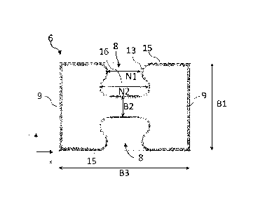
Figure 3 shows an embodiment of the dilation profile 6 in cross-
section. The floor element contact surfaces 9 are arranged
laterally and are provided for connection to the intermediate
floor elements 4, 5. The profile surfaces 15 are arranged at the
top and bottom and have a groove 8. The groove outer region 13
has a smaller minimum dimension Ni than the maximum dimension N2
of the groove inner region 16.
The dimension B1 of the dilation profile 6 along the floor
element contact surfaces 9 is smaller than the dimension B3
along the profile surface 15 of the dilation profile. The cross-
section of the dilation profile 6 is substantially rectangular.
The bottom portions of the upper and lower grooves 8 have no
connection and are spaced apart by a distance B2. Thus, the
groove 8 can act as a resilient structure and thermal
deformation in the transverse direction x of the dilation
profile 6 can be elastically compensated. This resilient
property of the dilation profile is supported by the fact that
the material thickness in the area of the groove 8, the concave-
convex structure and the bottom area of the groove is 1.6 mm.
The remaining area of the profile surface 15, however, has a
higher material thickness of 2.2 mm.
As can be seen in Figure 3, the groove 8 is designed as a
concave-convex curved structure in cross-section. In this way,
the force is distributed as evenly as possible over a larger
area of the groove 8 by deformation.
Figure 4 shows an embodiment of a car body 2 with an
intermediate floor 3 in cross section. The intermediate floor 3
separates an upper level 11 and a lower level 10. The
Date Recue/Date Received 2022-03-15
PSTAD024US /11.03.2022 21 ---
English application text.doc
intermediate floor 3 is attached by rivets as fastening elements
19 to a support 18 of each side wall 7.
A thermal insulation element 12 is also arranged between the
support 18 of the side wall 7. The thermal insulation element 12
minimizes the thermal conductivity between the side wall 7 of
the car body 2 and the intermediate floor 3.
Date Recue/Date Received 2022-03-15