Note: Descriptions are shown in the official language in which they were submitted.
CA 03153229 2022-03-03
WO 2021/063792 PCT/EP2020/076695
1
SYNTHESIS GAS ON DEMAND
TECHNICAL FIELD
A method is provided for rapidly switching a metal-catalysed steam methane
reforming
reaction of a feed gas from a first steady-state reaction condition (A) to a
second steady-
state reaction condition (B) or vice-versa.
BACKGROUND
Steam methane reforming (SMR) reactors are typically difficult to start-up due
to the
requirements of higher temperature chemistry and the associated heating.
Taking the SMR
reactor as an example, the fired reformer technology works by providing the
energy input by
combustion externally to the catalytic reactor system. In practice, this means
that the
process must be controlled by balancing two chemical reactors against each
other; on one
side the combustion reactor and on the other side the catalytic reactor. At
all time, these
must be balanced, and ¨ in particular ¨ the combustion side is not allowed a
large offset from
the catalyst side, otherwise overheating and thereby mechanical failure will
occur.
It only adds increased complexity that the catalytic reactor side of a typical
SMR reactor is
configured as several parallel tubes with one tube being able to process in
the order of 100-
300 Nm3/h gas and added capacity is gained by multiplying the number of tubes.
In practice,
this means that fired reformers are tedious to operate and care must be taken
to maintain
the process in steady state where an even degree of heat and gas distribution
between the
individual tubes is obtained.
Consequently, the ease by which steam methane reforming unit changes from one
steady-
state condition to another is typically slow because heating needs to be
balanced against heat
consumption. ATR technology also suffers from difficult start-up, where
preheating is
essential to avoid excessive sooting from the flame in the reactor. In some
instances this
requires preheating of large amounts of non-reactive gas before start-up is
possible. This also
influences the size and complexity of utility systems for such a plant.
Related technology is disclosed in co-pending applications PCT/EP2019/062423
and
PCT/EP2019/062424.
CA 03153229 2022-03-03
WO 2021/063792 PCT/EP2020/076695
2
One aim of the present technology is therefore to reduce the time it takes for
a steam
reforming reactor to change from one steady-state reaction condition to
another, e.g. during
start-up. Another aim of the present technology is to improve and/or simplify
control of a
steam reforming reaction in a steam reforming unit.
SUMMARY
A method for rapidly switching a metal-catalysed steam methane reforming
reaction of a feed
gas comprising hydrocarbons in a reactor system from a first steady-state
reaction condition
(A) to a second steady-state reaction condition (B) or vice-versa is provided.
The reactor system comprises a pressure shell housing a structured catalyst
arranged to
catalyze steam reforming of a feed gas comprising hydrocarbons, said
structured catalyst
comprising a macroscopic structure of an electrically conductive material,
said macroscopic
structure supporting a ceramic coating, where said ceramic coating supports a
catalytically
active material and wherein said reactor system is provided with heat
insulation between said
structured catalyst and said pressure shell and where a power supply placed
outside said
pressure shell is arranged to supply electrical power via electrical
conductors connecting to
said structured catalyst, allowing an electrical current to run through said
macroscopic
structure, thereby heating at least part of the structured catalyst.
The method comprises the steps of:
in said first steady-state reaction condition (A):
- supplying said feed gas to the reactor system in a first total flow, and
- supplying a first electrical power via electrical conductors
connecting an electrical
power supply placed outside said pressure shell to said structured catalyst,
thereby
allowing a first electrical current to run through said electrically
conductive material,
thereby heating at least part of the structured catalyst to a first
temperature at which said
feed gas is converted to a first product gas mixture over said structured
catalyst under said
first steady-state reaction conditions (A); and said first product gas is
outlet from the reactor
system;
and, in said second steady-state reaction condition (B):
CA 03153229 2022-03-03
WO 2021/063792 PCT/EP2020/076695
3
- supplying said feed gas to the reactor system in a second total flow,
- supplying a second electrical power via electrical conductors connecting
an electrical
power supply placed outside said pressure shell to said structured catalyst,
thereby
allowing a second electrical current to run through said electrically
conductive
material,
thereby heating at least part of the structured catalyst to a second
temperature; at which
said feed gas is converted to a second product gas mixture over said
structured catalyst
under said second steady-state reaction conditions (B); and said second
product gas is outlet
from the reactor system;
wherein said second electrical power is higher than said first electrical
power; and/or said
second total flow is higher than said first total flow.
Additional aspects of the present technology are set out in the dependent
claims, the figures
and the following description text.
LEGENDS TO THE FIGURES
Figure la shows a cross section through an embodiment of the inventive reactor
system with
a structured catalyst comprising an array of macroscopic structures, in a
cross section;
Figure lb shows the reactor system of Figure la with a part of the pressure
shell and heat
insulation layer removed;
Figure 2 is an enlarged view of a part of the reactor system;
Figures 3a and 3b show schematic cross sections through an embodiment of the
inventive
reactor system comprising a structured catalyst;
Figures 4 and 5 show an embodiment of a structured catalyst with an array of
macroscopic
structures as seen from above and from the side, respectively;
Figure 6 shows an embodiment of the structured catalyst of the invention;
Figures 7 and 8 show embodiments of a structured catalyst with connectors;
CA 03153229 2022-03-03
WO 2021/063792 PCT/EP2020/076695
4
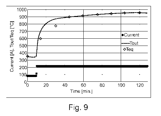
Figures 9 and 10 show the transient behaviour during an experiment of an
embodiment of
the invention.
DETAILED DISCLOSURE
A reactor system for carrying out an endothermic reaction of a feed gas, is
generally
provided, the reactor system comprising:
a structured catalyst arranged for catalyzing the endothermic reaction of a
feed gas, where
the structured catalyst comprises a macroscopic structure of electrically
conductive material,
where the macroscopic structure supports a ceramic coating and wherein the
ceramic coating
supports a catalytically active material;
- a structured catalyst arranged for catalyzing said endothermic reaction of a
feed gas, said
structured catalyst comprising an electrically conductive material and a
catalyst material;
- a pressure shell housing said structured catalyst;
- a heat insulation layer between said structured catalyst and said
pressure shell;
- a power supply placed outside said pressure shell is arranged to supply
electrical power via
electrical conductors connecting to said structured catalyst, allowing an
electrical current to
run through said macroscopic structure, thereby heating at least part of the
structured
catalyst
- at least two conductors electrically connected to said structured
catalyst and to an electrical
power supply placed outside the pressure shell, wherein the electrical power
supply is
dimensioned to heat at least part of the structured catalyst to a temperature
of at least
200 C by passing an electrical current through the electrically conductive
material.
The layout of the reactor system allows for feeding a pressurized feed gas to
the reactor
system at an inlet and directing this gas into the pressure shell of the
reactor system. Inside
the pressure shell, a configuration of heat insulation layers and inert
material is arranged to
direct the feed gas through the structured catalyst where it will be in
contact with the
catalyst material, where the catalytically active material will facilitate the
steam reforming
reaction. Additionally, the heating of the structured catalyst will supply the
required heat for
the endothermic reaction. The product gas from the heated structured catalyst
is led to the
reactor system outlet.
CA 03153229 2022-03-03
WO 2021/063792 PCT/EP2020/076695
The close proximity between the catalytically active material and the
electrically conductive
materials enables efficient heating of the catalytically active material by
close proximity heat
conduction from the resistance heated electrically conductive material. An
important feature
of the resistance heating process is thus that the energy is supplied inside
the object itself,
5 instead of being supplied from an external heat source via heat
conduction, convection and
radiation. Moreover, the hottest part of the reactor system will be within the
pressure shell of
the reactor system. Preferably, the electrical power supply and the structured
catalyst are
dimensioned so that at least part of the structured catalyst reaches a
temperature of 850-
1100 C when the endothermic reaction is the steam reforming reaction, a
temperature of
700-1200 C when the endothermic reaction is the hydrogen cyanide synthesis, a
temperature of 500-700 C when the endothermic reaction is dehydrogenation, a
temperature
of 200-300 C when the endothermic reaction is the methanol cracking, and a
temperature of
ca. 500 C when the endothermic reaction is the ammonia cracking reaction. The
surface area
of the electrically conductive material, the fraction of the electrically
conductive material
coated with a ceramic coating, the type and structure of the ceramic coating,
and the amount
and composition of the catalytically active catalyst material may be tailored
to the specific
endothermic reaction at the given operating conditions.
The electrically conductive material is suitably a macroscopic structure. As
used herein, the
term "macroscopic structure" is meant to denote a structure that is large
enough to be visible
with the naked eye, without magnifying devices. The dimensions of the
macroscopic structure
are typically in the range of centimeters or even meters. Dimensions of the
macroscopic
structure are advantageously made to correspond at least partly to the inner
dimensions of
the pressure shell housing the structured catalyst, saving room for the heat
insulation layer
and conductors. Two or more macroscopic structures may be connected in order
to provide
an array of macroscopic structures having at least one of the outer dimensions
in the range
of meters, such as 2 m or 5 m. Such two or more macroscopic structures may be
denoted
"an array of macroscopic structures". In this case the dimensions of an array
of macroscopic
structures are advantageously made to correspond at least partly to the inner
dimension of
the pressure shell housing the structured catalyst (saving room for the heat
insulation layer).
A conceivable array of macroscopic structures could take up a volume of 0.1 to
10 m3 or even
larger. The structured catalyst may comprise a single macroscopic structure or
an array of
macroscopic structures, where the macroscopic structure(s) support(s) a
ceramic coating
supporting catalytically active material. In an array of macroscopic
structures, the
macroscopic structures may be electrically connected to each other; however,
alternatively,
the macroscopic structures are not electrically connected to each other. Thus,
the structured
catalyst may comprise two or more macroscopic structures positioned adjacent
to each other.
The macroscopic structure(s) may be extruded and sintered structures or 3D
printed
CA 03153229 2022-03-03
WO 2021/063792 PCT/EP2020/076695
6
structures. A 3D printed macroscopic structure can be provided with or without
subsequent
sintering.
The physical dimensions of the macroscopic structure may be any appropriate
dimensions;
thus, the height may be smaller than the width of the macroscopic structure or
vice versa.
The macroscopic structure supports a ceramic coating, where the ceramic
coating supports a
catalytically active material. The term "macroscopic structure supporting a
ceramic coating"
is meant to denote that the macroscopic structure is coated by the ceramic
coating at, at
least, a part of the surface of the macroscopic structure. Thus, the term does
not imply that
all the surface of the macroscopic structure is coated by the ceramic coating;
in particular, at
least the parts of the macroscopic structure which are electrically connected
to the
conductors do not have a coating thereon. The coating is a ceramic material
with pores in the
structure, which allows for supporting catalytically active material on and
inside the coating.
Advantageously, the catalytically active material comprises catalytically
active particles
having a size in the range from about 5 nm to about 250 nm.
Preferably, the macroscopic structure has been manufactured by extrusion of a
mixture of
powdered metallic particles and a binder to an extruded structure and
subsequent sintering
of the extruded structure, thereby providing a material with a high geometric
surface area
per volume. Preferably, the extruded structure is sintered in a reducing
atmosphere to
provide the macroscopic structure. Alternatively, the macroscopic structure is
3D printed a
metal additive manufacturing melting process, viz. a 3D printing processes,
which do not
require subsequent sintering, such as powder bed fusion or direct energy
deposition
processes. Examples of such powder bed fusion or direct energy deposition
processes are
laser beam, electron beam or plasma 3D printing processes. As another
alternative, the
macroscopic structure may have been manufactured as a 3D metal structure by
means of a
binder-based metal additive manufacturing process, and subsequent sintered in
a non-
oxidizing atmosphere at a first temperature Ti, where Ti > 1000 C, in order to
provide the
macroscopic structure.
A ceramic coating, which may contain the catalytically active material, is
provided onto the
macroscopic structure before a second sintering in an oxidizing atmosphere, in
order to form
chemical bonds between the ceramic coating and the macroscopic structure.
Alternatively,
the catalytically active material may be impregnated onto the ceramic coating
after the
second sintering. When chemical bonds are formed between the ceramic coating
and the
macroscopic structure an especially high heat conductivity between the
electrically heated
macroscopic structure and the catalytically active material supported by the
ceramic coating
is possible, offering close and nearly direct contact between the heat source
and the
CA 03153229 2022-03-03
WO 2021/063792 PCT/EP2020/076695
7
catalytically active material of the structured catalyst. Due to close
proximity between the
heat source and the catalytically active material the heat transfer is
effective, so that the
structured catalyst can be very efficiently heated. A compact reactor system
in terms of gas
processing per reactor system volume is thus possible, and therefore the
reactor system
housing the structured catalyst may be compact.
As used herein, the terms "3D print" and "3D printing" is meant to denote a
metal additive
manufacturing process. Such metal additive manufacturing processes cover 3D
printing
processes in which material is joined to a structure under computer control to
create a three-
dimensional object, where the structure is to be solidified, e.g. by
sintering, to provide the
macroscopic structure. Moreover, such metal additive manufacturing processes
cover 3D
printing processes, which do not require subsequent sintering, such as powder
bed fusion or
direct energy deposition processes. Examples of such powder bed fusion or
direct energy
deposition processes are laser beam, electron beam or plasma 3D printing
processes.
The reactor system does not need a furnace and this reduces the overall
reactor size
considerably.
The electrically conductive material comprises Fe, Ni, Cu, Co, Cr, Al, Si or
an alloy thereof.
Such an alloy may comprise further elements, such as Mn, Y, Zr, C, Co, Mo or
combinations
thereof. Preferably, the electrically conductive material comprises Fe, Cr, Al
or an alloy
thereof. Such an alloy may comprise further elements, such as Si, Mn, Y, Zr,
C, Co, Mo or
combinations thereof. Preferably, the catalytically active material is
particles having a size
from 2 nm to 250 nm. Preferably, the conductors and the electrically
conductive material are
made of different materials than the electrically conductive material. The
conductors may for
example be of iron, nickel, aluminum, copper, silver or an alloy thereof. The
ceramic coating
is an electrically insulating material and will typically have a thickness in
the range of around
100 pm, say 10-500 pm.
The electrically conductive material is advantageously a coherent or
consistently intra-
connected material in order to achieve electrical conductivity throughout the
electrically
conductive material, and thereby achieve thermal conductivity throughout the
structured
catalyst and in particular providing heating of the catalyst material. By the
coherent or
consistently intra-connected material it is possible to ensure uniform
distribution of current
within the electrically conductive material and thus uniform distribution of
heat within the
structured catalyst. Throughout this text, the term "coherent" is meant to be
synonymous to
cohesive and thus refer to a material that is consistently intra-connected or
consistently
coupled. The effect of the structured catalyst being a coherent or
consistently intra-connected
material is that a control over the connectivity within the material of the
structured catalyst
CA 03153229 2022-03-03
WO 2021/063792 PCT/EP2020/076695
8
and thus the conductivity of the electrically conductive material is obtained.
It is to be noted
that even if further modifications of the electrically conductive material are
carried out, such
as provision of slits within parts of the electrically conductive material or
the implementation
of insulating material within the electrically conductive material, the
electrically conductive
material is still denoted a coherent or consistently intra-connected material.
The gas flow over the structured catalyst may be axial or co-axial with the
current path
through the structured catalyst, perpendicular to the current path or have any
other
appropriate direction in relation to the current path.
The term "steam reforming" is meant to denote a reforming reaction according
to one or
more of the following reactions:
CH4 + H20 4- CO + 3H2 (i)
CI-14 + 2H20 4- , CO2 + 4H2 (ii)
CH4 + CO2 4- 2C0 + 2H2 (iii)
Reactions (i) and (ii) are steam methane reforming reactions, whilst reaction
(iii) is the dry
methane reforming reaction.
For higher hydrocarbons, viz. CnHm, where r-1.2, m 4, equation (i) is
generalized as:
CnHm + n H2O 4- nC0 + (n + m/2)H2 (iv)
where r.1.2, m 4.
Typically, steam reforming is accompanied by the water gas shift reaction (v):
CO + H20 4- CO2 + H2 (v)
The term "steam methane reforming" is meant to cover the reactions (i) and
(ii), the term
"steam reforming" is meant to cover the reactions (i), (ii) and (iv), whilst
the term
"methanation" covers the reverse reaction of reaction (i). In most cases, all
of these
reactions (i)-(v) are at, or close to, equilibrium at the outlet from the
reactor system.
CA 03153229 2022-03-03
WO 2021/063792 PCT/EP2020/076695
9
The term "prereforming" is often used to cover the catalytic conversion of
higher
hydrocarbons according to reaction (iv). Prereforming is typically accompanied
by steam
reforming and/or methanation (depending upon the gas composition and operating
conditions) and the water gas shift reaction. Prereforming is often carried
out in adiabatic
reactors but may also take place in heated reactors.
The steam reforming reaction is highly endothermic. High temperatures
typically in excess of
800-850 C are needed to reach acceptable conversions of the methane in the
feed. A SMR
consists of a number of tubes filled with catalyst pellets placed inside a
furnace. The tubes
are typically 10-13 meters long and will typically have an inner diameter
between 80 and 160
mm. Burners placed in the furnace provide the required heat for the reactions
by combustion
of a fuel gas. A maximum average heat flux of 80000-90000 kcal/h/m2 of inner
tube surface
is not uncommon. There is a general limitation to the obtainable heat flux due
to mechanical
constraints and the capacity is therefore increased by increasing the number
of tubes and the
furnace size. More details on the SMR type reactor system can be found in the
art, e.g.
"Synthesis gas production for FT synthesis"; Chapter 4, p.258-352, 2004.
The term "electrically conductive" is meant to denote materials with an
electrical resistivity in
the range from: 10-5 to 10-8 S2-m at 20 C. Thus, materials that are
electrically conductive are
e.g. metals like copper, silver, aluminum, chromium, iron, nickel, or alloys
of metals.
Moreover, the term "electrically insulating" is meant to denote materials with
an electrical
resistivity above 10 S2-m at 20 C, e.g. in the range from 109 to 1025Q-m at 20
C.
When the reactor system comprises a heat insulation layer between the
structured catalyst
and the pressure shell, appropriate heat and electrical insulation between the
structured
catalyst and the pressure shell is obtained. The presence of heat insulating
layer between the
pressure shell and the structured catalyst assists in avoiding excessive
heating of the
pressure shell, and assists in reducing thermal losses to the surroundings.
The temperatures
of the structured catalyst may reach up to about 1300 C, at least at some
parts thereof, but
by using the heat insulation layer between the structured catalyst and the
pressure shell the
temperature of the pressure shell can be kept at significantly lower
temperatures of say
500 C or even 100 C, which is advantageous as typical construction steel
materials typically
are unsuitable for pressure bearing application at temperatures above 1000 C.
Moreover, a
heat insulating layer between the pressure shell and the structured catalyst
assists in control
of the electrical current within the reactor system, since heat insulation
layer is also
electrically insulating. The heat insulation layer could be one or more layers
of solid material,
such as ceramics, inert material, bricks or a gas barrier or a combination
thereof. Thus, it is
also conceivable that a purge gas or a confined gas constitutes or forms part
of the heat
insulation layer.
CA 03153229 2022-03-03
WO 2021/063792 PCT/EP2020/076695
Moreover, it should be noted that the term "heat insulating material" is meant
to denote
materials having a thermal conductivity of about 10 W=rn-i=K-1 or below.
Examples of heat
insulating materials are ceramics, bricks, fiber materials, alumina based
materials, zirconia
based materials and similar.
5 Advantageously, any relevant gaps between structured catalyst, the heat
insulation layer, the
pressure shell, and/or any other components inside the reactor system is
filled with inert
material, e.g. in the form of inert pellets. Such gaps are e.g. a gap between
the lower side of
the structured catalyst and the bottom of the pressure shell and a gap between
the sides of
the structured catalyst and the insulation layer covering the inner sides of
the pressure shell.
10 The inert material may e.g. be a ceramic material in the form of pellets
or tiles. The inert
material assists in controlling the gas distribution through the reactor
system and in
controlling the flow of the gas through the structured catalyst. Moreover, the
inert material
typically has a heat insulating effect.
The pressure shell suitably has a design pressure of between 2 bar and 30 bar.
The actual
operating pressure will be determined by the endothermic reaction, the size of
the plants,
among other aspects. As the hottest part of the reactor system is the
electrically conductive
material, which will be surrounded by heat insulation layer and within the
pressure shell of
the reactor system, the temperature of the pressure shell can be kept
significantly lower than
the maximum process temperature. This allows for having a relative low design
temperature
of the pressure shell of e.g. 700 C or 500 C or preferably 300 C or 100 C of
the pressure
shell whilst having maximum process temperatures of 400 C, or even 900, or
even 1100 C,
or even up to 1300 C on the structured catalyst. Material strength is higher
at the lower of
these temperatures (corresponding to the design temperature of the pressure
shell as
indicated above). This offers advantages when designing the chemical reactor.
Suitably, the
pressure shell has a design pressure of between 30 bar and 200 bar, preferably
between 80
and 180 bar.
The resistivity of the electrically conductive material is suitably between 10-
5 S2 =m and 10-7 S2
=m. A material with a resistivity within this range provides for an efficient
heating of the
structured catalyst when energized with a power source. Graphite has a
resistivity of about
10-5 Q=rn at 20 C, kanthal has a resistivity of about 10-6 Q=rn at 20 C,
whilst stainless steel
has a resistivity of about 10-7 Q=rn at 20 C. The electrically conductive
material may for
example be made of FeCrAlloy having a resistivity of ca. 1.540-6 Q=rn at 20 C.
Typically, the pressure shell comprises an inlet for letting in process gas
and an outlet for
letting out product gas, wherein the inlet is positioned close to a first end
of the pressure
shell and the outlet is positioned close to a second end of the pressure
shell, and wherein the
CA 03153229 2022-03-03
WO 2021/063792 PCT/EP2020/076695
11
at least two conductors both are connected to the structured catalyst at a
position on the
structured catalyst closer to the inlet than to the outlet. Hereby, the at
least two conductors
can be placed in the substantially colder part of the reactor system as the
inlet gas will have
lower temperature than the product gas, the electrically conductive material
will be colder in
the colder in the most upstream part of the material due to the heat consumed
by the
progress of the chemical reaction, and the feed gas fed led through the inlet
may cool the at
least two conductors before being heated by the heated structured catalyst
further along the
path of the gas over the heated structured catalyst. It is an advantage that
the temperature
of all electrically conducting elements except the electrically conductive
material is kept down
in order to protect the connections between the conductors and the structured
catalyst. When
the temperature of the conductors and other electrically conducting elements,
except the
electrically conductive material, is relatively low, less limitations on
materials suitable for the
conductors and other electrically conducting elements, except the electrically
conductive
material, exists. When the temperature of the electrically conducting elements
increase, the
resistivity thereof increases; therefore, it is desirable to avoid unnecessary
heating of all
other parts than the electrically conductive materials within the reactor
system. The term
"electrically conducting elements, except the electrically conductive
material" is meant to
cover the relevant electrically conducting elements arranged to connect the
power supply to
the structured catalyst.
It should be noted, that the system of the invention may include any
appropriate number of
power supplies and any appropriate number of conductors connecting the power
supply/supplies and the electrically conductive material(s) of the structured
catalyst. As
mentioned above, a power supply is placed outside said pressure shell and is
arranged to
supply electrical power via electrical conductors connecting to said
structured catalyst,
.. allowing an electrical current to run through said macroscopic structure,
thereby heating at
least part of the structured catalyst.
Suitably, the at least two conductors are led through a pressure shell in a
fitting so that the
at least two conductors are electrically insulated from the pressure shell.
The fitting may be,
partly, of a plastic and/or ceramic material. The term "fitting" is meant to
denote a device
that allows for mechanically connecting two pieces of hardware in a pressure
bearing
configuration. Thereby, the pressure within the pressure shell may be
maintained even
though the at least two conductors are lead through it. Non-limiting examples
of the fittings
may be an electrically insulating fitting, a dielectric fitting, a power
compression seal, a
compression fitting or a flange. The pressure shell typically comprises side
walls, end walls,
flanges and possibly further parts. The term "pressure shell" is meant to
cover any of these
components.
CA 03153229 2022-03-03
WO 2021/063792 PCT/EP2020/076695
12
The pressure shell may further comprise one or more inlets close to or in
combination with at
least one of the fittings in order to allow a cooling gas to flow over,
around, close to or inside
at least one conductor within said pressure shell. Hereby, the conductors are
cooled and thus
the temperature that the fitting experiences is kept down. If the cooling gas
is not used, the
conductors may be heated by the feed gas to the reactor system, resistance
heating of
conductor due to the applied current, and/or heat conduction from the
structured catalyst.
The cooling gas could e.g. be hydrogen, nitrogen, steam, carbon dioxide or
mixtures thereof.
The temperature of the cooling gas at entry into the pressure shell may be
e.g. about 100 C
or 200 C or 250 C. In an embodiment, the conductor(s) is (are) hollow so that
the cooling
gas may flow through the conductor(s) and cool it (them) from within. By
keeping the
temperature of the fitting low, e.g. at around 100-200 C, it is easier to have
a leak tight
configuration. Typically, a part of the feed gas, such as one of the
reactants, is fed to the
pressure shell as the cooling gas. In another embodiment, part of the feed gas
or a gas with
the same composition as the feed gas is used as cooling gas.
The reactor system may further comprise an inner tube in heat exchange
relationship with
the structured catalyst, where the inner tube is adapted to withdraw a product
gas from the
structured catalyst so that the product gas flowing through the inner tube or
tubes is in heat
exchange relationship with the gas flowing over the structured catalyst, but
electrically
separated from the structured catalyst. This is a layout which here is denoted
a bayonet
reactor system. In this layout the product gas within the inner tube assists
in heating the
process gas flowing over the structured catalyst. The electrical insulation
between the inner
tube and the structured catalyst could be gas in the form of a gap or distance
between the
inner tube and the structured catalyst or inert material loaded around the
inner tube and the
structured catalyst. The gas may pass through the structured catalyst in an up-
flow or a
down-flow direction.
The connection between the structured catalyst and the at least two conductors
may be a
mechanical connection, a welded connection, a brazed connection or a
combination thereof.
The structured catalyst may comprise terminals physically and electrically
connected to the
structured catalyst in order to facilitate the electrical connection between
the electrically
conductive material and the at least two conductors. The term "mechanical
connection" is
meant to denote a connection where two components are held together
mechanically, such
as by a threaded connection or by clamping, so that a current may run between
the
components.
The electrically conductive materials placed in an array of electrically
conductive materials
may be electrically connected to each other. The connection between the two or
more
electrically conductive materials may be by mechanical connection, clamping,
soldering,
CA 03153229 2022-03-03
WO 2021/063792 PCT/EP2020/076695
13
welding or any combination of these connection methods. Each electrically
conductive
material may comprise terminals in order to facilitate the electrical
connections. The two or
more electrically conductive materials may be connected to the power supply in
serial or
parallel connection. The electrical connection between the two or more
electrically conductive
.. materials is advantageously coherent and uniform along the connection
surface between the
two or more electrically conductive materials, so that the two or more
electrically conductive
materials act as a single coherent or consistently intra-connected material;
hereby, uniform
electrical conductivity throughout the two or more electrically conductive
materials is
facilitated. Alternatively, or additionally, the structured catalyst may
comprise an array of
.. electrically conductive materials that are not electrically connected to
each other. Instead,
two or more electrically conductive materials are placed together within the
pressure shell,
but not connected electrically to each other. In this case, the structured
catalyst thus
comprises electrically conductive materials connected in parallel to the power
supply.
A ceramic coating, with or without catalytically active material, may be added
directly to a
metal surface of the electrically conductive material by wash coating. The
wash coating of a
metal surface is a well-known process; a description is given in e.g.
Cybulski, A., and Moulijn,
J. A.," Structured catalysts and reactors", Marcel Dekker, Inc, New York,
1998, Chapter 3,
and references herein. The ceramic coat may be added to the surface of the
electrically
conductive material and subsequently the catalytically active material may be
added;
alternatively, the ceramic coat comprising the catalytically active material
is added to the
macroscopic structure or electrically conductive material. The ceramic coating
may for
example be an oxide comprising Al, Zr, Mg, Ce and/or Ca. Exemplary coatings
are calcium
aluminate or a magnesium aluminum spine!. Such a ceramic coating may comprise
further
elements, such as La, Y, Ti, K or combinations thereof. The ceramic coating is
an electrically
insulating material and will typically have a thickness in the range of around
100 pm, say 10-
500 pm.
Extruding and sintering or 3D printing a macroscopic structure results in a
uniformly and
coherently shaped macroscopic structure, which can afterwards be coated with
the ceramic
coating.
The electrically conductive material and the ceramic coating may have been
sintered in an
oxidizing atmosphere in order to form chemical bonds between the ceramic
coating and the
electrically conductive material; this provides for an especially high heat
conductivity
between the electrically conductive material and the catalytically active
material supported by
the ceramic coating. Thereby, the structured catalyst is compact in terms of
heat transfer to
.. the active catalytic site, and a reactor system housing the structured
catalyst may be
compact and limited mainly by the rate of the chemical reaction. There is no
heat transfer
CA 03153229 2022-03-03
WO 2021/063792 PCT/EP2020/076695
14
from outside the pressure shell to the structured catalyst as would be the
case through the
tube walls to the catalyst within the tubes for the SMRs used in the art of
steam reforming.
In an embodiment, the structured catalyst has at least one electrically
insulating part
arranged to increase the current path between the conductors to a length
larger than the
largest dimension of the structured catalyst. The provision of a current path
between the
conductors larger than the largest dimension of the structured catalyst may be
by provision
of electrically insulating part(s) positioned between the conductors and
preventing the
current running through some part of the structured catalyst. Such
electrically insulating
parts are arranged to increase the current path and thus increase the
resistance through the
structured catalyst. Hereby, the current path through the structured catalyst
can be e.g.
more than 50%, 100%, 200%, 1000%, or even 10000% longer than the largest
dimension
of the structured catalyst.
Moreover, such electrically insulating parts are arranged to direct the
current from one
conductor, which is closer to the first end of the structured catalyst than to
the second end,
towards the second end of the structured catalyst and back to a second
conductor closer to
the first end of the structured catalyst than to the second end. Preferably,
the current is
arranged to run from the first end of the structured catalyst to the second
and back to the
first end. As seen in the figures, the first end of the structured catalyst is
the top end thereof.
The arrow indicated "z" in figures 5-7 indicates a z-axis along the length of
the structured
.. catalyst. The principal current path throughout the structured catalyst
will have a positive or
negative value of z-coordinate of the accompanied current density vector along
most of the
length of the current path. By principal current path is meant the path of the
electrons
through a macroscopic structure of the structured catalyst with the highest
current density.
The principal current path can also be understood as the path having the
minimum length
through the macroscopic structure of the structured catalyst. Seen
geometrically, the
principal current path can be quantified as the largest current density vector
within a plane
perpendicular to the gas flow direction of a coherent section of the
macroscopic structure. At
the bottom of the structured catalyst, as shown in the figures, the current
will turn, and here
the z- coordinate of the accompanied current density vector will be zero.
As used herein, the term coherent section is meant to denote a cross-section
area of the
macroscopic structure wherein all walls of the coherent section are
geometrically connected
to one or more other walls of the coherent section within the same plane.
In an embodiment, the structured catalyst has at least one electrically
insulating part
arranged to direct a current through the structured catalyst in order to
ensure that for at
least 70% of the length of said structured catalyst, a current density vector
of a principal
CA 03153229 2022-03-03
WO 2021/063792 PCT/EP2020/076695
current path has a non-zero component value parallel to the length of said
structured
catalyst. Thus, for at least 70% of the length of the structured catalyst, the
current density
vector will have a positive or negative component value parallel to the length
of the
structured catalyst. Thus, for at least 70%, e.g. for 90% or 95%, of the
length of structured
5 catalyst, viz, along the z-axis of the structured catalyst as seen in
figures 5 to 10, the current
density vector of a principal current path will have a positive or negative
value along the z-
axis. This means that the current is forced from the first end of the
structured catalyst
towards the second end, and subsequently is forced towards the first end
again. The
temperature of the gas entering the first end of the structured catalyst and
the endothermic
10 steam reforming reaction taking place over the structured catalyst
absorbs heat from the
structured catalyst. For this reason, the first end of the structured catalyst
remains colder
than the second end, and by ensuring that the current density vector of the
principal current
path has a non-zero component value parallel to the length of said structured
catalyst, this
takes place with a substantially continuously increasing temperature profile,
which gives a
15 controllable reaction front. In an embodiment the current density vector
has a non-zero
component value parallel to the length of said structured catalyst in 70% of
the length of said
structured catalyst, preferably 80%, more preferably 90%, and even more
preferably 95%. It
should be noted that the term "the length of the structured catalyst" is meant
to denote the
dimension of the structured catalyst in the direction of the gas flow. In the
structured
catalysts as shown in the figures, the length is the longitudinal direction,
viz, the longest
dimension thereof. This is indicated by the arrow denote z in some of the
figures.
Non-limiting examples of insulating parts are cuts, slits, or holes in the
structure. Optionally,
a solid insulating material such as ceramics in cuts or slits in the structure
can be used. In a
case where the solid insulating material is a porous ceramic material, the
catalytically active
material may advantageously be incorporated in the pores, by e.g.
impregnation. A solid
insulating material within a cut or slit assists in keeping the parts of the
structured catalyst
on the sides of the cut or slit from each other. As used herein, the term
"largest dimension of
the structured catalyst" is meant to denote the largest inner dimension of the
geometrical
form taken up by the structured catalyst. If the structured catalyst is box-
formed, the largest
dimension would be the diagonal from one corner to the farthest corner, also
denoted the
space diagonal.
It should be noted that even though the current through the structured
catalyst may be
arranged to twist or wind its way through the structured catalyst due to the
electrically
insulating parts arranged to increase the current path, the gas passing
through the reactor
system is inlet at one end of the reactor system, passes over the structured
catalyst once
before being outlet from the reactor system. Inert material is advantageously
present in
relevant gaps between the structured catalyst and the rest of the reactor
system to ensure
CA 03153229 2022-03-03
WO 2021/063792 PCT/EP2020/076695
16
that the gas within the reactor system passes over the structured catalyst and
the catalyst
material herein.
The length of the gas passage through the structured catalyst is suitably less
than the length
of the passage of current from one electrode through the structured catalyst
and to the next
electrode. The ratio of the length of the gas passage to the length of the
current passage
may be less than 0.6, or 0.3, 0.1, or even down to 0.002.
Typically, the structured catalyst has electrically insulating parts arranged
to make the
current path through the structured catalyst a zigzag path. Here, the terms
"zigzag path" and
"zigzag route" is meant to denote a path that has corners at variable angles
tracing a path
from one conductor to another. A zigzag path is for example a path going
upwards, turning,
and subsequently going downwards. A zigzag path may have many turns, going
upwards and
subsequently downwards many times through the structured catalyst, even though
one turn
is enough to make the path a zigzag path.
It should be noted that the insulating parts arranged to increase the current
path are not
necessarily related to the ceramic coating on the electrically conductive
material; even
though this ceramic coating is also considered electrically insulating, it
does not change the
length of the current path between the conductors connected to the
electrically conductive
material.
The macroscopic structure may have a plurality of parallel channels, a
plurality of non-
parallel channels and/or a plurality of labyrinthic channels, where the
channels have walls
defining the channels. Thereby, several different forms of the macroscopic
structure can be
used as long as the surface area of the structured catalyst exposed to the gas
is as large as
possible. In a preferred embodiment, the macroscopic structure has parallel
channels, since
such parallel channels render a structured catalyst with a very small pressure
drop. In a
preferred embodiment, parallel longitudinal channels are skewed in the
longitudinal direction
of the macroscopic structure. In this way, molecules of the gas flowing
through the
macroscopic structure will mostly tend to hit a wall inside the channels
instead of just flowing
straight through a channel without being in contact with a wall. The dimension
of the
channels should be appropriate in order to provide a macroscopic structure
with a sufficient
resistivity. For example, the channels could be quadratic (as seen in cross
section
perpendicular to the channels) and have a side length of the squares of
between 1 and 3
mm; however, channels having a maximum extent in the cross section of up to
about 4 cm
are conceivable. The walls may e.g. have a thickness of between 0.2 and 2 mm,
such as
about 0.5 mm, and the ceramic coating supported by the walls has a thickness
of between 10
CA 03153229 2022-03-03
WO 2021/063792 PCT/EP2020/076695
17
pm and 500 pm, such as between 50 pm and 200 pm, such as 100 pm. In another
embodiment, the macroscopic structure of the structured catalyst is cross-
corrugated.
In general, when the macroscopic structure is extruded or 3D printed, the
pressure drop from
the inlet to the outlet of the reactor system may be reduced considerably
compared to a
reactor where the catalyst material is in the form of pellets.
Suitably, the reactor system further comprises a bed of a second catalyst
material upstream
the structured catalyst within the pressure shell. Here, the term "upstream"
is seen from the
flow direction of the feed gas. Thus, the term "upstream" is here meant to
denote that the
feed gas is directed through the bed of second catalyst material prior to
reaching the
structured catalyst. This provides for a situation where the second catalyst
material can be
arranged for pre conditioning the feed stream. No specific heating needs to be
provided to
the bed of second catalyst material; however, the bed of second catalyst
material may be
heated indirectly if it is in close proximity to the structured catalyst.
Alternatively, the second
catalyst material may be heated. In order to clarify the terminology used
here, it is noted
that the term "structured catalyst" may also be denoted "a first catalyst
material" to
distinguish it from the second and/or third and/or fourth catalyst material.
The reactor system may further comprise a third catalyst material in the form
of catalyst
pellets, extrudates or granulates loaded into the channels of the macroscopic
structure. In
this embodiment, the reactor system will thus have a catalytically active
material in the
coating of the macroscopic structure as well as a third catalyst material in
the form catalyst
pellets, extrudates or granulates within the channels of the macroscopic
structure. The pellets
are e.g. prepared in a dimension to loosely match the size of channels to form
a single string
of pellets stacked upon each other within a channel of the macroscopic
structure.
Alternatively, the pellets, extrudates or granulates may be prepared in a
dimension
significantly smaller than the channel size to form a packed bed inside each
channel. As used
herein, the term "pellet" is meant to denote any well-defined structure having
a maximum
outer dimension in the range of millimeters or centimeters, while "extrudate"
and "granulate"
are meant to define a catalyst material with a maximum outer dimension defined
within a
range.
A bed of fourth catalyst material may be placed within the pressure shell and
downstream the
structured catalyst. Such fourth catalyst material may be in the form of
catalyst pellets,
extrudates or granulates.
Therefore the first, second, third, and fourth catalyst material may be
catalyst materials
suitable for the steam reforming reaction. In a configuration where a
combination of the
CA 03153229 2022-03-03
WO 2021/063792 PCT/EP2020/076695
18
second, third, and fourth catalyst material is included in the reactor system,
the catalyst of
each catalyst material can be different.
The geometric surface area of the macroscopic structure may be between 100 and
3000
m2/m3, such as between 500 and 1100 m2/m3. Typically, the material of the
macroscopic
structure is chosen as a material arranged to supply a heat flux of 500 W/m2
to 50000 W/m2
by resistance heating of the material. Preferably, resistance heating of the
material supplies a
heat flux of between 5 kW/m2 and 12 kW/m2, for example between 8 kW/m2 and 10
kW/m2.
The heat flux is given as heat per geometric surface area of the surface
exposed to the gas.
The predetermined temperature range of the gas exiting the pressure shell/the
reactor
system is the range from 200 to 1300 C, depending on the endothermic reaction
facilitated.
The product gas outlet temperature from the structured catalyst is measured
directly beneath
or on the most downstream surface of the structured catalyst. Measuring
technology can be
thermocouples (by voltage drop), resistance temperature detectors or infrared
detection. The
measuring point can be separated from the structured catalyst and be embedded
in
downstream inert/catalyst, or be directly on the surface with an insulating
surface coverage.
In order to control the temperature of a reaction, the heat added/removed from
a reactor
system needs to be balanced against the heat consumed/produced by the chemical
reaction.
The addition/removal of heat needs to be balanced against the rate of reaction
and especially
the approach to equilibrium as defined by 16, where ig is the ratio between
the reaction
quotient and the equilibrium constant of a reaction. A value off? approaching
1 means the
reaction mixture is close to equilibrium and values approaching 0 means the
reaction mixture
is far from equilibrium. In general, it is desirable to have as high a rate of
reaction as
possible, which is achieved at a low fl, as long as the temperature can be
sufficiently
controlled in parallel by balancing the energy added.
In the case of the endothermic steam methane reforming reaction, heat needs to
be added to
ensure the reaction continues to proceed as otherwise the reaction will be
equilibrated and
the fl value will approach 1 and the reaction will slow down. However, on the
other side, it is
undesirable if the temperature increases faster than the rate of reaction can
follow as
exposing unconverted hydrocarbons to high temperatures can result in carbon
formation. A
good way to follow this behavior is by the approach to equilibrium. The
approach to
equilibrium of the steam reforming reaction is found by initially calculating
the reaction
quotient (Q) of the given gas as:
CA 03153229 2022-03-03
WO 2021/063792 PCT/EP2020/076695
19
Yco = Yi34
Q 2 p2
YCH4 = Y1-120
Here y, is the molar fraction of compound j, and P is the total pressure in
bar. This is used to
determine the equilibrium temperature (Teq) at which the given reaction
quotient is equal to
the equilibrium constant:
Q = KSMR
where KSMR - is the thermodynamic equilibrium constant of the steam methane
reforming
reaction. The approach to equilibrium of the steam methane reforming
(ATapp,sõ) reaction is
then defined as:
ATapp,SMR = T ¨ Teg
Where T is the bulk temperature of the gas surrounding the catalyst material
used, such as
the structured catalyst.
To ensure good performance of a steam reforming catalyst, it is desirable that
the catalyst
continuously works towards decreasing ATapp,smR. Classically, large scale
industrial SMRs have
been designed to obtain an approach to equilibrium of 5-20 C at the outlet
thereof.
With the current invention, it is possible to control the heat flux and match
this directly to the
kinetic performance of the structured catalyst, as these are independent to
some extent.
The structured catalyst within said reactor system suitably has a ratio
between the area
equivalent diameter of a horizontal cross section through the structured
catalyst and the
height of the structured catalyst in the range from 0.1 to 2Ø The area
equivalent diameter
of the cross section through the reactor system is defined as the diameter of
a circle of
equivalent area as the area of the cross section. When the ratio between the
area equivalent
.. diameter and the height of the structured catalyst is between 0.1 and 2.0,
the pressure shell
housing the structured catalyst may be relatively small compared to other
reactor systems
for endothermic reactions such as the current SMRs.
Typically, the gas flows through the reactor system in an upflow or downflow
direction, so
that the gas flows through channels in the structured catalyst along the
height thereof. When
CA 03153229 2022-03-03
WO 2021/063792 PCT/EP2020/076695
the structured catalyst comprises a number of or an array of macroscopic
structures, the
individual macroscopic structures within the array may be placed side by side,
on top of each
other or in a combination thereof. It is stressed that, when the structured
catalyst comprises
more than one macroscopic structures, the dimensions of the structured
catalyst are the
5 dimensions of the more than one macroscopic structures. Thus, as an
example, if the
structured catalyst comprises two macroscopic structures, each having the
height h, put on
top of each other, the height of the structured catalyst is 2h.
The volume of the structured catalyst is chosen in consideration of the
desired feed
conversion and/or temperature out of the reactor system correlated to the heat
generation
10 capacity of the electrically conductive material.
Suitably, the height of the reactor system is between 0.5 and 7 m, more
preferably between
0.5 and 3 m. Exemplary values of the height of the reactor system is a height
of less than 5
meters, preferably less than 2 m or even 1 m. The dimensions of the reactor
system and of
the structured catalyst within the reactor system are correlated; of course,
the pressure shell
15 and heat insulation layer render the reactor system somewhat larger than
the structured
catalyst itself. For comparison, industrial scale SMRs are typically
constructed of catalyst
tubes having a length of 10 m or above to maximize external surface area of
the tubes. The
present invention is advantageous in that such confinements in the design of
the reactor
system are superfluous.
20 The reaction system described above is ¨ in contrast to fired reformers
¨ not a segregated
system. As heating is not transferred across a pressure bearing wall, the risk
of mechanical
failure is not high. From a catalyst point of view, temporary overheating is
not a problem, it
will just produce a very hot synthesis gas. This means that start-up is fast
in comparison and
in practice the eSMR can be started by applying a given voltage and then the
system will
work towards a thermal equilibration to reach steady state without any
additional operator
input.
In a main aspect, therefore, a method for rapidly switching a metal-catalysed
steam methane
reforming reaction of a feed gas comprising hydrocarbons in a reactor system
from a first
steady-state reaction condition (A) to a second steady-state reaction
condition (B) or vice-
versa; is therefore provided.
Reaching a steady state condition is defined as when central process
parameters (such as
feed flow, outlet temperature, and reactant conversion) have reached a value
within 15% of
the average process value for the given process parameter for the subsequent
hour.
CA 03153229 2022-03-03
WO 2021/063792 PCT/EP2020/076695
21
A condition of the invention, A or B, involves a state where the catalyst of
the system is
heated by an electrical power balanced to heat the product gas outlet
temperature from the
structured catalyst to a temperature between 300 and 1300 C at a pressure
between 5 barg
and 150 barg with a feedstock comprising hydrocarbons (such as methane,
ethane, or
propane), hydrogen, and steam, and any of carbon monoxide, carbon dioxide,
nitrogen,
argon, or oxygen in a total flow rate of 300 Nm3/h to 100 000 Nm3/h. When the
feedstock
passes the monolith, it will react towards equilibration of the steam
reforming and water gas
shift reaction.
In an embodiment of the invention, the method includes an initial reaction
condition A where
the feedstock consists of 8.7% CO2, 0.2% Nz, 21.5% C1-14, 3.7% Hz, 0.1% CO,
and 65.7%
H20 in a total flow of 9757 Nm3/h having a temperature of 415 C at a pressure
of 27.0 barg.
Supplying a first electrical power of 725 kW generates an almost equilibrated
gas composed
of 9.4% CO2, 0.2% Nz, 20.0% C1-14, 7.9% Hz, 0.2% CO, and 62.2% H20 in a total
flow of
9978 Nm3/h having a temperature of 500 C at a pressure of 26.5 barg.
Switching to
condition B over a period of about 90 min while applying a second electrical
power of 9710
kW generates an almost equilibrated gas composed of 6.1% CO2, 0.2% Nz, 0.5% C1-
14, 46.8%
Hz, 14.8% CO, and 31.7% H20 in a total flow of 13830 Nm3/h having a
temperature of 990
C at a pressure of 26.5 barg.
In an embodiment of the invention, the method includes an initial reaction
condition A where
the feedstock consists of 12.6% CO2, 0.3% Nz, 33.9% C1-14, 2.5% Hz, 0.1% CO,
and 50.6%
H20 in a total flow of 17488 Nm3/h having a temperature of 405 C at a
pressure of 77.0
barg. Supplying a first electrical power of 19.3 MW generates an almost
equilibrated gas
composed of 5.1% CO2, 0.2% Nz, 6.5% C1-14, 47.5% Hz, 19.8% CO, and 21.0% H20
in a total
flow of 25998 Nm3/h having a temperature of 1005 C at a pressure of 75.5
barg. Switching
to condition B over a period of about 130 min while increasing the feedstock
total flow to
43323 Nm3/h and applying a second electrical power of 46.9 MW generates an
almost
equilibrated gas composed of 5.3% CO2, 0.2% Nz, 7.0% C1-14, 46.7% Hz, 19.3%
CO, and
21.5% H20 in a total flow of 64408 Nm3/h having a temperature of 995 C at a
pressure of
75.5 barg.
The term "vice versa" is used to mean that the method applies equally when
switching from
the first reaction condition (A) to the second reaction condition (B) as when
switching from
the second reaction condition (B) to the first reaction condition (A).
Notably, a switch from
condition A to B is considered completed when the process values of the system
have
reached within 85% of steady state conditions.
CA 03153229 2022-03-03
WO 2021/063792 PCT/EP2020/076695
22
The reactor system is as described above; i.e. it comprises a pressure shell
housing a
structured catalyst arranged to catalyze steam reforming of a feed gas
comprising
hydrocarbons, said structured catalyst comprising a macroscopic structure of
an electrically
conductive material, said macroscopic structure supporting a ceramic coating,
where said
ceramic coating supports a catalytically active material and wherein said
reactor system is
provided with heat insulation between said structured catalyst and said
pressure shell. All
details described above in relation to the reactor system are relevant for the
present
technology.
The method of the invention comprises the steps of:
in said first steady-state reaction condition (A):
- supplying said feed gas to the reactor system in a first total flow, and
- supplying a first electrical power via electrical conductors connecting
an electrical
power supply placed outside said pressure shell to said structured catalyst,
thereby
allowing a first electrical current to run through said electrically
conductive material,
thereby heating at least part of the structured catalyst to a first
temperature at which said
feed gas is converted to a first product gas mixture over said structured
catalyst under said
first steady-state reaction conditions (A); and said first product gas is
outlet from the reactor
system;
and, in said second steady-state reaction condition (B):
- supplying said feed gas to the reactor system in a second total flow,
- supplying a second electrical power via electrical conductors connecting
an electrical
power supply placed outside said pressure shell to said structured catalyst,
thereby
allowing a second electrical current to run through said electrically
conductive
material,
thereby heating at least part of the structured catalyst to a second
temperature; at which
said feed gas is converted to a second product gas mixture over said
structured catalyst
under said second steady-state reaction conditions (B); and said second
product gas is outlet
from the reactor system;
CA 03153229 2022-03-03
WO 2021/063792
PCT/EP2020/076695
23
To achieve the first and second steady-state reaction conditions (A) and (B),
the second
electrical power is higher than said first electrical power; and/or said
second total flow is
higher than said first total flow.
Notably, an increase in total flow will increase the input of cool feed gas,
thus cooling the
.. structured catalyst, and reducing the reactivity so that second steady-
state reaction condition
(B) is achieved. A significant change in flow will change the energy required
for the process.
A change in total flow may include a change in total flow with no
compositional change or a
change in the composition, such as increasing the steam flow or changing part
of the
feedstock.
In one embodiment, the ratio of total gas feed flow in said first reaction
condition A to said
second reaction condition B (A:B) is at least 1:10. Switching between
condition A and B
consequently allows for significant increased/decreased production of product
gas. This is
advantageous when the invention is used for e.g. energy storage where excess
electric
energy from the energy grid is available and in this way can be stored as
chemical energy, or
.. vice versa for increasing availability of electric energy in the grid when
it is needed
elsewhere. Additionally, the embodiment allows for using the invention to
supply large
amounts of product gas in periods where downstream processes demands it, while
having the
invention operating in a standby condition otherwise. This is advantageously
if there is no
continuous demand for the product gas.
.. In another embodiment, the product gas outlet temperature from the
structured catalyst in
reaction condition B is between 50 C to 800 C higher, such as between 100 C to
500 C
higher, preferably between 150 C to 400 C higher, than the product gas outlet
temperature
from the structured catalyst in reaction condition A. This allows for rapidly
starting up the
reactor system from a cold state to operating conditions. This is
advantageously in the
.. situation of system start-up, where the start-up procedure involves steps
including:
= Heating process equipment in a non-condensing gas to a temperature above
the
condensation point of the steady state conditions of the plant at full
operating
capacity,
= Pressurising the feed gas constituents,
= Feeding feed gas constituents to the reactor system while applying a first
electrical
power,
= Switching to a higher operating temperature by a applying a second
electrical power.
CA 03153229 2022-03-03
WO 2021/063792 PCT/EP2020/076695
24
In this way, all steps of the start-up procedure are relatively fast. In the
closest prior art, of
e.g. a tubular reformer, the step of switching to higher operating temperature
is a very slow
process and is time-wise an order of magnitude greater than the other steps.
The product gas outlet temperature from the structured catalyst in reaction
condition B is
typically no more than 50 C higher than the product gas outlet temperature
from the
structured catalyst in reaction condition A. This allows for rapidly changing
the between
condition A and B, without significantly changing the product gas composition
from the
system. In this way, the demand for the product gas for downstream processes
of the reactor
system can easily be supplied in different quantities without interfering
significantly in the
chemical environment of these.
In one embodiment, the switch between reaction condition A and B includes a
gradual change
of the total gas feed flow from said first total flow to said second total
flow and simultaneous
gradual change of the applied electrical potential over said electrically
conductive material
from said first to said second electrical power. In this way, the product gas
composition can
be held almost constant also during the transition stage. In an embodiment,
the gradual
changes are made in such a way where the flow is increased in small steps
while increasing
the electrical power to maintain an almost constant product gas outlet
temperature from the
structured catalyst.
In an embodiment, the reactor system further comprises a control system
arranged to
control the electrical power supply to ensure that the temperature of the gas
exiting the
pressure shell lies in a predetermined range and/or to ensure that the
conversion of the feed
gas lies in a predetermined range. The control of the electrical power supply
is the control of
the electrical output from the power supply. The control of the electrical
power supply may
e.g. be carried out as a control of the voltage and/or current from the
electrical power
supply, as a control of whether the electrical power supply is turned on or
off or as a
combination hereof. The power supplied to the structured catalyst can be in
the form of
alternating current or direct current.
According to one embodiment, a proportional¨integral¨derivative (PID)
controller controls the
electrical potential based on feedback reading of the process value of product
gas outlet
temperature from the structured catalyst.
The method described herein allows rapid switching between conditions A and B.
Suitably,
therefore, the switch between reaction conditions A and B takes place over a
period of less
than 3 hours, such as less than 2 hours, such as less than 60 min, preferably
less than 30
CA 03153229 2022-03-03
WO 2021/063792 PCT/EP2020/076695
min, and even more preferably less than 15 min. This is far quicker than the
corresponding
switch between reaction conditions A and B which would be possible with a
fired reformer.
In one embodiment, the switch between reaction condition A and B involves
supplying a
second electrical power to the structured catalyst. This suitably occurs while
keeping the total
5 flow essentially constant.
In one aspect, the switch between reaction condition A and B comprises a
transition state
between said reaction conditions A and B; said transition state comprising a
first period in
which the electrical power is switched off, followed by a second period in
which said second
electrical power of condition B is supplied to the structured catalyst. This
allows for faster
10 establishment of a steady state.
In one aspect, the switch between reaction condition A and B comprises a
transition state
between said reaction conditions A and B; said transition state comprising a
first period in
which a third electrical power is supplied to the structured catalyst,
followed by a second
period in which said second electrical power of condition B is supplied to the
structured
15 catalyst, said third electrical power being higher than the second
electrical power. This allows
for faster establishment of a steady state.
The process may comprise further steps carried out on the product gas, such as
purification,
pressurization, heating, cooling, etc. to provide the final product gas for an
application
downstream the reactor system of this invention.
20 It should be noted that the feed gas may comprises individual feed
gasses and that the step
of pressurizing the feed gas may comprise pressurizing individual feed gasses
individually.
Moreover, it should be noted that the order in which the steps of the process
are written are
not necessarily the order in which the process steps take place, in that two
or more steps
may take place simultaneously, or the order may be different that indicated
above.
25 In an embodiment, the process comprises the step of pressurizing the gas
upstream the
pressure shell to a pressure of up to at least 2 bar. The chosen operating
pressure is defined
by the endothermic reaction and the integration of the reactor in the
surrounding process
steps.
In an embodiment of the process according to the invention, the temperature of
the feed gas
let into the reactor system is between 100 C and 700 C. However, in all
embodiments the
temperature and the pressure of the feed gas are adjusted to ensure that the
feed gas is
above the dew point.
CA 03153229 2022-03-03
WO 2021/063792 PCT/EP2020/076695
26
In an embodiment of the process of the invention, the structured catalyst is
heated so that
the maximum temperature of the structured catalyst lies between 200 C and 1300
C. The
used temperature will be dependent on the endothermic reaction. The maximum
temperature
of the structured catalyst depends upon the material of the electrically
conductive material;
thus, if the electrically conductive material is of FeCrAlloy, which melts at
a temperature of
between 1380 C and 1490 C (depending on the actual alloy), the maximum
temperature
should be somewhat below the melting point, such as at about 1300 C if the
melting point of
the electrically conductive material is at about 1400 C, as the material will
become soft and
ductile when approaching the melting point. The maximum temperature may
additionally be
limited by the durability of the catalyst material, the coating and the
catalytically active
material.
In an embodiment the process according to the invention further comprises the
step of
inletting a cooling gas through an inlet through the pressure shell in order
to allow a cooling
gas to flow over at least one conductor and/or fitting. The cooling gas may
advantageously
be hydrogen, nitrogen, steam, carbon dioxide or any other gas suitable for
cooling the area
or zone around the at least one conductor. A part of the feed gas may be fed
to the pressure
shell as the cooling gas.
In an embodiment according to the invention, the process further comprises the
step of
inletting a cooling gas through an inlet through the pressure shell in order
to allow a cooling
gas to flow over at least one conductor and/or fitting. The cooling gas may be
any
appropriate gas; examples of such gasses are hydrogen, nitrogen, steam, carbon
dioxide or
mixtures thereof. The cooling gas may flow through the conductor(s) and cool
it (them) from
within; in this case, the conductor(s) need(s) to be hollow to accommodate the
cooling gas
flowing within it/them.
Steam reforming of hydrocarbons takes place according to reaction (i)-(v),
above. The
catalyst material for the reaction may be Ni/A1203, Ni/ZrO2, Ni/MgA1203,
Ni/CaA1203,
Ru/MgAl203, or Rh/MgA1203. The catalytically active material may be Ni, Ru,
Rh, Ir, or a
combination thereof, while the ceramic coating may be A1203, ZrO2, MgAl203,
CaAl203, or a
combination therefore and potentially mixed with oxides of Y, Ti, La, or Ce.
The maximum
temperature of the reactor may be between 850-1300 C. The pressure of the feed
gas may
be 15-180 bar, preferably about 25 bar. In an embodiment said macroscopic
structure is
made of an alloy of Fe Cr Al, supporting a ceramic coating of a ZrO2 and
MgA1204 mixture,
with nickel as catalytically active material.
The following is a detailed description of embodiments of the invention
depicted in the
accompanying drawings. The embodiments are examples and are in such detail as
to clearly
CA 03153229 2022-03-03
WO 2021/063792 PCT/EP2020/076695
27
communicate the invention. However, the amount of detail offered is not
intended to limit the
anticipated variations of embodiments; but on the contrary, the intention is
to cover all
modifications, equivalents, and alternatives falling within the spirit and
scope of the present
invention as defined by the appended claims.
DETAILED DESCRIPTION OF THE FIGURES
Throughout the Figures, like reference numbers denote like elements.
Figure la shows a cross section through an embodiment of a reactor system 100
according to
the invention. The reactor system 100 comprises a structured catalyst 10,
arranged as an
array of macroscopic structures 5. Each macroscopic structure 5 in the array
is coated with a
ceramic coating impregnated with catalytically active material. The reactor
system 100
moreover comprises conductors 40, 40' connected to a power supply (not shown
in the
Figures) and to the structured catalyst 10, viz, the array of macroscopic
structures. The
conductors 40, 40' are led through the wall of a pressure shell 20 housing the
structured
catalyst and through insulating material 30 on the inner side of the pressure
shell, via fittings
50. The conductors 40' are connected to the array of macroscopic structures 5
by conductor
contact rails 41.
In an embodiment, the electrical power supply supplies a voltage of 26V and a
current of
1200A. In another embodiment, the electrical power supply supplies a voltage
of 5V and a
current of 240A. The current is led through electrical conductors 40, 40' to
conductor contact
rails 41, and the current runs through the structured catalyst 10 from one
conductor contact
rail 41, e.g. from the conductor contact rail seen to the left in Figure la,
to the other
conductor contact rail 41, e.g. the conductor contact rail seen to the right
in Figure la. The
current can be both alternating current, and e.g. run alternating in both
directions, or direct
current and run in any of the two directions.
The macroscopic structures 5 are made of electrically conductive material.
Especially
preferred is the alloy kanthal, also known as FeCrAlloy, consisting of
aluminum, iron and
chrome. The ceramic coating, e.g. an oxide, coated onto the structure
catalysts 5 is
impregnated with catalytically active material. The conductors 40, 40' are
made in materials
like iron, aluminum, nickel, copper or alloys thereof.
During operating, a feed gas enters the reactor system 100 from above as
indicated by the
arrow 11 and exits the reactor system from the bottom thereof as indicated by
the arrow 12.
CA 03153229 2022-03-03
WO 2021/063792 PCT/EP2020/076695
28
Figure lb shows the reactor system 100 of Figure la with a part of the
pressure shell 20 and
heat insulation 30 layer removed and Figure 2 is an enlarged view of a part of
the reactor
system 100. In Figures lb and 2 the connections between conductors 40' and
conductor
contact rails 41 are shown more clearly than in Figure la. Moreover, it is
seen that the
conductors 40 are led through the walls of the pressure shell in a fitting 50,
and that the one
conductor 40 is split up into three conductors 40' within the pressure shell.
It should be
noted, that the number of conductors 40' may be any appropriate number, such
as smaller
than three or even larger than three.
In the reactor system shown in Figures la, lb and 2, the conductors 40, 40'
are led through
the wall of a pressure shell 20 housing the structured catalyst and through
insulating material
30 on the inner side of the pressure shell, via fittings 50. Feed gas for
steam reforming is
inlet into the reactor system 100 via an inlet in the upper side of the
reactor system 100 as
shown by the arrow 11, and reformed gas exits the reactor system 100 via an
outlet in the
bottom of the reactor system 100 as shown by the arrow 12. Moreover, one or
more
additional inlets (not shown in Figures la to 2) advantageously exist close to
or in
combination with the fittings 50. Such additional inlets allow a cooling gas
to flow over,
around, close to, or inside at least one conductor within the pressure shell
to reduce the
heating of the fitting. The cooling gas could e.g. be hydrogen, nitrogen,
steam, carbon
dioxide or mixtures thereof. The temperature of the cooling gas at entry into
the pressure
shell may be e.g. about 100 C.
In the reactor system 100 shown in Figures la to 2, inert material (not shown
in Figures la-
2) is advantageously present between the lower side of the structured catalyst
10 and the
bottom of the pressure shell. Moreover, inert material is advantageously
present between the
outer sides of the structured catalyst 10 of macroscopic structures 5 and the
insulating
material 30. Thus, one side of the insulating material 30 faces the inner side
of the pressure
shell 20 and the other side of the insulating material 30 faces the inert
material. The inert
materiel is e.g. ceramic material and may be in the form of pellets. The inert
material assists
in controlling the pressure drop across the reactor system 100 and in
controlling the flow of
the gas through the reactor system 100, so that the gas flows over the
surfaces of the
structured catalyst 10.
Figures 3a and 3b show schematic cross sections through an embodiment of the
inventive
reactor system 100', 100" comprising a structured catalyst 10'. The structured
catalyst 10'
may consist of a single macroscopic structure with ceramic coating supporting
catalytically
active material or it may contain two or more macroscopic structures. Each of
the reactor
systems 100', 100" comprises a pressure shell 20 and a heat insulation layer
80 between the
structured catalyst 10' and the pressure shell 20. Inert material 90 can be
used to fill the gap
CA 03153229 2022-03-03
WO 2021/063792 PCT/EP2020/076695
29
between the structured catalyst 10' and the heat insulation layer or the
pressure shell 20. In
Figures 3a and 3b, the inert material 90 is indicated by dotted area; the
inert material 90
may be in any appropriate form, e.g. in the form of inert pellets, and it is
e.g. of ceramic
material. The inert material 90 assists in controlling the pressure drop
through the reactor
.. system and in controlling the flow of the gas through the reactor system.
Moreover, the inert
material typically has a heat insulating effect.
From Figures 3a and 3b it is seen that the reactor systems 100', 100" further
comprise an
inner tube 15 in heat exchange relationship with the structured catalyst 10'.
The inner tube
is adapted to withdraw a product gas from the structured catalyst 10' so that
the product
10 .. gas flowing through the inner tube or tubes is in heat exchange
relationship with the gas
flowing over the structured catalyst; however, the inner tube 15 is
electrically insulated from
the structured catalyst 10' by either a heat insulation layer 80, inert
material 90, a gap, or a
combination. This is a layout which is denoted a bayonet reactor system. In
this layout, the
product gas within the inner tube assists in heating the process gas flowing
over the
15 macroscopic structure. In the layouts shown in Figure 3a and 3b, the
feed gas enters the
reactor system 100', 100" as indicated by the arrow 11, and continues into the
structured
catalyst 10' as indicated by the arrows 13. During the passage of the feed gas
over the
structured catalyst 10', it undergoes the steam reforming reaction. The gas
exiting the
structured catalyst 10' is at least partly reformed. The at least partly
reformed gas flows from
the structured catalyst 10' into the inner tube 15 as indicated by the arrows
14, and exits the
inner tube as indicated by the arrows 12. Even though the heat insulation
layer 80 is present
between the inner tube 15 and the structured catalyst 10', some heat transfer
will take place
from the gas within the inner tube 15 and the gas within the structured
catalyst 10' or
upstream the structured catalyst 10'. In the embodiments shown in Figures 3a
and 3b, the
feed gas flow downwards through the structured catalyst 10' and upwards
through the inner
tube 15; however, it is conceivable that the configuration was turned upside-
down so that
the feed gas would flow upwards through the structured catalyst 10' and
downwards through
the inner tube 15.
Figures 4 and 5 show an embodiment of a structured catalyst comprising an
array of
macroscopic structures as seen from above and from the side, respectively.
Figure 4 shows a
structured catalyst 10 comprising an array of macroscopic structure 5 seen
from above, viz.
as seen from the arrow 11 in Figures la and lb. The array has 6 rows, viz. la,
lb, lc, ld, le
and lf, of five macroscopic structures 5. The macroscopic structures 5 in each
row are
connected to its neighboring macroscopic structure (s) in the same row and the
two
outermost macroscopic structures in each row are connected to a conductor
contact rail 41.
The neighboring macroscopic structures 5 in a row of macroscopic structures
are connected
to each other by means of a connection piece 3.
CA 03153229 2022-03-03
WO 2021/063792 PCT/EP2020/076695
Figure 5 shows the structured catalyst 10 having an array of macroscopic
structures 5 of
Figure 4 seen from the side. From Figure 5, it can be seen that each
macroscopic structure 5
extends longitudinally perpendicular to the cross section seen in Figure 4.
Each macroscopic
structure 5 has a slit 60 cut into it along its longitudinal direction (see
Figure 5). Therefore,
5 when energized by the power source, the current enters the array of
macroscopic structures
5 via a conductor contact rail 41, is led through the first macroscopic
structure 5 downwards
until the lower limit of the slit 60 and is subsequently led upwards towards a
connection piece
3. The current is led via a corresponding zigzag path, downwards and upwards,
through each
macroscopic structure 5 in each row la-if of macroscopic structures 5 in the
array 10. This
10 configuration advantageously increases the resistance over the
structured catalyst 10.
Figure 6 shows a structured catalyst 10 according to the invention in a
perspective view. The
structured catalyst 10 comprises a macroscopic structure that is coated with a
ceramic
coating impregnated with catalytically active material. Within the structured
catalyst are
channels 70 extending along the longitudinal direction (shown by the arrow
indicate 'IV in
15 Figure 6) of the macroscopic structure 5; the channels are defined by
walls 75. In the
embodiment shown in Figure 6, the walls 75 define a number of parallel, square
channels 70
when seen from the direction of flow as indicated by the arrow 12. The
structured catalyst 10
has a substantially square perimeter when seen from above, defined by the edge
lengths el
and e2. However, the perimeter could also be circular or another shape.
20 .. The walls 75 of the structured catalyst 10 are of extruded or 3D printed
material coated with
a ceramic coating, e.g. an oxide, which has been coated onto the macroscopic
structure. In
the Figures, the ceramic coating is not shown. The ceramic coating is
impregnated with
catalytically active material. The ceramic coating and thus the catalytically
active material are
present on every wall within the structured catalyst 10 over which the gas
flow flows during
25 operation and interacts with the heated surface of the structured
catalyst and the catalytically
active material.
Thus, during use in a reactor system for steam reforming, a hydrocarbon feed
gas flows
through the channels 70 and interacts with the heated surface of the
structured catalyst and
with the catalytically active material supported by the ceramic coating.
30 In the structured catalyst 10 shown in Figure 6 a slit 60 has been cut
into the structured
catalyst 10. This slit 60 forces a current to take a zigzag route, in this
instance downwards
and subsequently upwards, within the macroscopic structure thereby increasing
the current
path and thus the resistance and consequently the heat dissipated within the
macroscopic
structure. The slit 60 within the macroscopic structure may be provided with
embedded
CA 03153229 2022-03-03
WO 2021/063792 PCT/EP2020/076695
31
insulating material in order to ensure that no current flows in the transverse
direction of the
slit 60.
The channels 70 in the structured catalyst 10 are open in both ends. In use of
the structured
catalyst in a reactor system, a hydrocarbon feed gas flows through the unit,
in the direction
shown by arrows 11 and 12 in Figures la and lb, and gets heated via contact
with the walls
75 of the channels 70 and by heat radiation. The heat initiates the desired
steam reforming
process. The walls 75 of the channels 70 may e.g. have a thickness of 0.5 mm,
and the
ceramic coating coated onto the walls 75 may e.g. have a thickness of 0.1 mm.
Even though
the arrows 11 and 12 (see Figures la and lb) indicate that the flow of the
hydrocarbon feed
gas is down-flow, the opposite flow direction, viz, an up-flow, is also
conceivable.
Figure 7 shows the structured catalyst 10 of Figures la and lb in a
perspective view and with
connectors 7 attached. The connectors 7 each connect a part of the structured
catalyst 10 to
a conductor 40. The conductors 40 are both connected to a power supply (not
shown). Each
of the connectors 7 are connected to an upper part of the structured catalyst.
When the
conductors 40 are connected to a power supply, an electrical current is led to
the
corresponding connector 7 via the conductor and runs through the structured
catalyst 10.
The slit 60 hinders the current flow in a transverse direction (horizontal
direction of Figure 7)
throughout its lengths along the height h of the structured catalyst 10.
Therefore, the current
runs in a direction downwards as seen in Figure 7 in the part of the
structured catalyst along
the slit 60, subsequently it runs transversely to the longitudinal direction
below the slit 60 as
seen in Figure 7 and finally the current runs upwards in the longitudinal
direction of the
structured catalyst to the other connector 7. The connectors 7 in Figure 7 are
mechanically
fastened to the structured catalyst by means of inter alia mechanical
fastening means such
as screws and bolts. However, additional or alternative fastening means are
conceivable. In
.. an embodiment, the electrical power supply generates a voltage of 3V and a
current of 400A.
The connectors 7 are e.g. made in materials like iron, aluminum, nickel,
copper or alloys
thereof.
As mentioned, the structured catalyst 10 is coated with a ceramic coating,
such as an oxide,
supporting the catalytically active material. However, the parts of the
structured catalyst 10,
which are connected to the connectors 7, should not be coated with an oxide.
Instead, the
macroscopic structure of the structured catalyst should be exposed or
connected directly to
the connectors 7 in order to obtain a good electrical connection between the
macroscopic
structure and the connector.
When the connectors 7 and thus the conductors 40 are connected to the same end
of the
.. structured catalyst 10, viz, the upper end as seen in Figure 7, the gas
entering into a reactor
CA 03153229 2022-03-03
WO 2021/063792 PCT/EP2020/076695
32
system housing the structured catalyst 10 would be able to cool the connectors
7 and the
conductors 40. For instance, the hydrocarbon gas entering into such a reactor
system would
have a temperature of 400 C or 500 C and would thus keep the connectors 7 and
conductors
40 from reaching temperatures much higher than this temperature.
Figure 8 shows another embodiment of a structured catalyst 10" with connectors
7". The
structured catalyst 10" is e.g. the structured catalyst as shown in Figure 6.
Each of the
connectors 7" has three holes at an upper side thereof for connection to
conductors (not
shown). A piece of electrically insulating material 61 is inside the slit 60
(see Figure 6) of the
structured catalyst 10".
Figure 9 shows an example of the current invention as generated from
experimental data on
a laboratory embodiment of the invention. In a first state A the system is
operating at a fixed
feed flow of 100 NI/h having a composition of 31.8% CH4, 2.4% Hz, and 66.8%
H20 at a total
pressure of 10 barg and an inlet temperature of 200 C.
In this stage a current of 81 A runs in the monolith at a voltage drop of 1V.
At the time mark
of 10 min, the electrical potential is increased to 2.6 V over a few seconds,
which gives a new
current of 218 A defining stage B.
This results in an immediate increase in temperature and after 20 min this has
increased
from 350 C to 875 C and is within 10% of the steady state process value of the
given
condition set at 950 C. The final adjustment towards the steady state value is
a function of
thermal equilibration of the system and a complete heating to steady state of
all elements in
the system, including insulation and reactor elements. The open diamond
symbols of the
figure additionally shows the so called equilibrium temperature of the steam
reforming
reaction as evaluated by GC-TCD during the run, which is found to match the
operating
temperature closely. This means that the product gas of the system constantly
is close to
equilibrium, even during the change of operating stages. When observed, the
off-set between
the equilibrium temperature and operating temperature is only an experimental
artefact of a
delay in gas sampling relative to the temperature sampling.
Figure 10 shows an example of the current invention as generated from
experimental data on
a laboratory embodiment of the invention. In a first state A the system is
operating at a fixed
feed flow of 100 NI/h having a composition of 31.8% CH4, 2.4% Hz, and 66.8%
H20 at a total
pressure of 2.5 barg and an inlet temperature of 200 C.
CA 03153229 2022-03-03
WO 2021/063792 PCT/EP2020/076695
33
In this stage a current of 20 A runs in the monolith at a voltage drop of 2.7
V. At the time
mark of 16 min, the electrical potential is decreased to 1.8 V, which gives a
new current of
140 A defining stage B.
This results in an immediate decrease in temperature and after 30 min this has
decreased
.. from 950 C to 650 C and is within 5% of the steady state process value of
the given
condition set at 630 C. The final adjustment towards the steady state value is
a function of
thermal equilibration of the system and a complete cooling to steady state of
all elements in
the system, including insulation and reactor elements. The open diamond
symbols of the
figure additionally shows the so called equilibrium temperature of the steam
reforming
reaction as evaluated by GC-TCD during the run, which is found to match the
operating
temperature closely. This means that the product gas of the system constantly
is close to
equilibrium, even during the change of operating stages.
The present invention has been described with reference to a number of aspects
and
embodiments. These aspects and embodiments may be combined at will by the
person skilled
.. in the art while remaining within the scope of the patent claims.