Note: Descriptions are shown in the official language in which they were submitted.
CA 03153527 2022-03-04
WO 2021/055822 PCT/US2020/051595
TENSIONED SCREEN ASSEMBLY
CROSS REFERENCE TO RELATED APPLICATION
[0001] This application claims priority to U.S. Provisional Patent
Application No.
62/902,688; filed on September 19, 2019, the disclosure of which is expressly
incorporated
herein by reference.
BRIEF DESCRIPTION OF THE DRAWINGS
[0002] The accompanying drawings form a part of this disclosure and are
incorporated into
the specification. The drawings illustrate example embodiments of the
disclosure and, in
conjunction with the description and claims, serve to explain various
principles, features, or
aspects of the disclosure. Certain embodiments of the disclosure are described
more fully below
with reference to the accompanying drawings. However, various aspects of the
disclosure may
be implemented in many different forms and should not be construed as being
limited to the
implementations set forth herein.
[0003] FIG. 1 illustrates an example attrition screening machine, according
to an
embodiment.
[0004] FIG. 2 illustrates a top perspective view of a circular screen
assembly, according to an
embodiment.
[0005] FIG. 3 illustrates a bottom perspective view of the circular screen
assembly of FIG. 2,
according to an embodiment.
[0006] FIG. 4A illustrates a reinforced molded polyurethane screen having
reinforcements
along two directions, according to an embodiment.
[0007] FIG. 4B illustrates a reinforced molded polyurethane screen having
reinforcements
along a single first direction, according to an embodiment.
[0008] FIG. 4C illustrates a reinforced molded polyurethane screen having
reinforcements
along a single second direction, according to an embodiment.
1
CA 03153527 2022-03-04
WO 2021/055822 PCT/US2020/051595
[0009] FIG. 5 illustrates a process of fabricating a circular screen
assembly, according to an
embodiment.
[0010] FIG. 6 illustrates a circular frame having a support grid structure,
according to an
embodiment.
[0011] FIG. 7 illustrates a rectangular frame having a support grid
structure, according to an
embodiment.
[0012] FIG. 8 illustrates a triangular frame having a support grid
structure, according to an
embodiment.
[0013] FIG. 9A illustrates a portion of a molded polyurethane screen having
various support
members, according to an embodiment.
[0014] FIG. 9B illustrates a larger portion of the molded polyurethane
screen of FIG. 9A,
according to an embodiment.
[0015] FIG. 10A illustrates an edge view of the molded polyurethane screen
of FIGS. 9A and
9B, according to an embodiment.
[0016] FIG. 10B illustrates an enlarged edge view of the molded
polyurethane screen of FIG.
10A, according to an embodiment.
[0017] FIG. 11 illustrates a further enlarged edge view of the molded
polyurethane screen of
FIG. 10A, according to an embodiment.
[0018] FIG. 12 illustrates a molded polyurethane screen having square
apertures, according
to an embodiment.
[0019] FIG. 13 is a flowchart illustrating a method of generating a screen
assembly,
according to an embodiment.
2
CA 03153527 2022-03-04
WO 2021/055822 PCT/US2020/051595
DETAILED DESCRIPTION
[0020] This disclosure generally relates to material screening systems and
methods. For
example, disclosed embodiments relate to screening members, screening
assemblies, methods for
fabricating screening members and assemblies, and methods of screening
materials. Material
screening includes the use of vibratory screening machines, which provide a
capability to excite
an installed screen such that materials placed upon the screen may be
separated to a desired
level. Oversized materials are separated from undersized materials. Over time,
screens wear and
require replacement. As such, screens are designed to be replaceable.
[0021] Disclosed embodiments provide improved screens and screen assemblies
that may be
used in screening machines such as those described in U.S. Patent Nos.:
8,584,866; 9,010,539;
9,375,756; and 9,403,192; the disclosure of each of which is expressly
incorporated herein by
reference. These screening machines, referred to as attrition screening
devices, including for
example, sifters, gyratory sifters, or graters, include a class of vibratory
devices used to separate
sized particles, as well as to separate solids from liquids. Sifters are used
to screen, for example,
minerals, feed material, plastic resins, and powders during industrial sorting
and/or
manufacturing operations.
[0022] Because sifters may be in continuous use, repair operations and
associated downtimes
need to be minimized as much as possible. Conventional sifters include
screening assemblies that
have a plate or frame as a base and a wire mesh, cloth, or other perforated
filter overlay
positioned as a screen over the plate or frame. These filter screens often
wear out over time due
to the particulate motion in the sifters, and subsequently require
replacement. Conventional
screens used in these sifters often wear out in three weeks or less. Also,
woven wire cloth screens
are problematic in that they can have inconsistent openings, sizes, or other
irregularities due to
inaccuracies in the weaving process.
[0023] Disclosed embodiments provide screens and screen assemblies to be
used in these
sifting screening machines that are safer, longer lasting, more easily
removable and replaceable,
lighter, and provide more consistent and accurate opening sizes than existing
screens. Disclosed
embodiments include reinforced molded polyurethane screens that may be
tensioned over a
frame of any desired shape to generate screen assemblies having corresponding
desired shapes.
3
CA 03153527 2022-03-04
WO 2021/055822 PCT/US2020/051595
For example, a screen assembly may have a perimeter that is a circle, square,
rectangle, triangle,
pentagon, hexagon, or other multi-sided polygon. In other embodiments, the
perimeter need not
have any specific symmetry and may be an asymmetric smooth or piecewise-smooth
curve. In
this regard, a frame of any shape (e.g., circular, triangular, square,
rectangular, pentagonal,
hexagonal, etc.) may be used as a substrate on which a molded polyurethane
screen may be
attached. Screens may be placed under tension when attaching such screens to a
frame. Screens
may be reinforced along one or two dimensions and may be placed under uniaxial
or biaxial
tension.
[0024] FIG. 1 illustrates an example attrition screening machine 100,
according to an
embodiment. Attrition screening machine 100 may be used to separate dry
materials of various
sizes. In this example, attrition screening machine 100 includes two circular
screens 102a and
102b. A first material 104 may be introduced into attrition screening machine
100 through an
inlet 106 of attrition screening machine 100. First material 104 may be
separated by first screen
102a into a first oversized component and a first undersized component. The
first oversized
component that does not fall through first screen 102a may be removed from
attrition screening
machine 100 as a first separated material 108a through a first outlet 110a of
attrition screening
machine 100. The first undersized component that falls through first screen
102a may be further
separated into a second oversized component and a second undersized component.
[0025] The second oversized component that does not fall through screen
102b may be
removed from attrition screening machine 100 as a second separated material
108b through a
second outlet 110b. Lastly, the second undersized component that falls through
second screen
102b may be removed from attrition screening machine 100 as a third separated
material 108c
through a third outlet 110c of attrition screening machine 100. Separation of
first material 104 in
to first 108a, second 108b, and third 108c separated materials may be assisted
by vibrations of
screens 102a and 102b that may be provided by a vibratory motor 112. Other
embodiment
attrition screening machines may include greater or fewer screens to
respectively separate greater
or fewer components of an input material. Also, further embodiment attrition
screening
machines may take various other shapes.
4
CA 03153527 2022-03-04
WO 2021/055822 PCT/US2020/051595
[0026] FIG. 2 illustrates a top perspective view of a circular screen
assembly 200, according
to an embodiment. Screen assembly 200 includes a molded polyurethane screen
202 attached to
a circular frame 204. Polyurethane screen 202 may be reinforced as described,
for example, in
U.S. Patent Nos.: 9,010,539; 9,375,756; and 9,403,192 (cited above).
Alternatively, screen 202
may be provided without reinforcements. Screen 202 may be placed under
uniaxial or biaxial
tension before attaching screen 202 to frame 204, as described in greater
detail below. Screen
202 may be attached to frame 204 using various attachment methods. For
example, screen 202
may be bonded to frame 204 using various adhesives or may be attached to frame
204 using
clamps or various fasteners.
[0027] Frame 204 may be constructed of metal, plastic, nylon, etc., or any
suitable structural
material. For example, frame 204 may be an injection molded nylon structure.
In further
embodiments, frame 204 may be constructed as a plurality of separate pieces
(not shown) that
may be assembled into a final shape. For example, a circular frame such as
frame 204 may
include various circular arc segments (not shown) and may be configured to be
snapped together
to form frame 204.
[0028] FIG. 3 illustrates a bottom perspective view of the circular screen
assembly 200 of
FIG. 2, according to an embodiment. In this example, frame 204 includes a
circular outer
support region 302 that supports a plurality of support structures forming a
support framework
304. In this view, support framework 304 includes horizontal support
structures 304a and 304b,
as well as a plurality of vertical support structures 304c, 304d, 304e, etc.
Screen 202 (e.g., see
FIG. 2) may be attached to frame 204 at various locations. For example, screen
202 may be
attached to circular outer support region 302 as well as to support framework
304. Such
attachment of screen 202 to both outer support region 302 as well as to
support framework 304
leads to a secure attachment in which screen 202 is configured to closely
follow movement of
frame 204 during vibrational excitation of screen assembly 200 on a
vibrational screening
machine.
[0029] In other embodiments, screen 202 may be more loosely bound to frame
204. For
example, screen 202 may be bonded only to circular outer support region 302.
Such
configuration would allow motion of screen 202 relative to support framework
304 during
CA 03153527 2022-03-04
WO 2021/055822 PCT/US2020/051595
vibrational excitation of screen assembly 200 on a vibrational screening
machine. Such relative
motion may be advantageous for certain applications. For example, in a dry
screening or sifting
application (i.e., attrition screening) a 2nd order movement or vibration of
screen 202 relative to
support framework 304 may aid in de-blinding of the screen (i.e., removing
particles that may in
certain situations become stuck in screen openings).
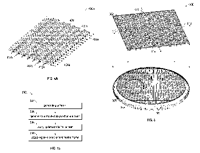
[0030] FIG. 4A illustrates a reinforced molded polyurethane screen 400a
having
reinforcements along two directions, according to an embodiment. Screen 400a
is similar to
reinforced molded polyurethane screens described, for example, in U.S. Patent
Nos.: 9,010,539;
9,375,756; and 9,403,192 (cited above). As shown in FIG. 4A, screen 400a has
first and second
members 402a and 402b with bi-directional reinforcement members 404a and 404b
molded
integrally therewith. In this regard, first members 402a include reinforcement
members 404a
molded integrally therewith. In this example, first reinforcement members 404a
may have a
thickness in a range of about 0.006 inches to about 0.015 inches. Second
members 402b may
include reinforcement members 404b molded integrally therewith. In this
example,
reinforcement members 404b may have a thickness in the range of about 0.015
inches to about
0.040 inches. Screen 404a includes apertures 406 formed as spaces between the
plurality of first
402a and second 402b members. In further embodiments, screens may have other
dimensions
for similar features.
[0031] FIGS. 4B and 4C illustrate respective reinforced molded polyurethane
screens 400b
and 400c, each having reinforcements along only a single direction, according
to embodiments.
Screens 400b and 400c are similar to screen 400a of FIG. 4A. In this regard,
each of screens
400b and 400c include first and second members 402a and 402b forming a
rectangular screening
surface having apertures 406. However, screen 400b only has reinforcement
members 404a that
reinforce first members 402a, while second members 402b are not reinforced. In
contrast, screen
400c only has reinforcement members 404b that reinforce second members 402b,
while first
members 402a are not reinforced.
[0032] As shown in FIGS. 4A to 4C, screen openings 406 are elongated with a
greater length
than width. In this example, screen openings 406 may be about 0.044 mm to
about 4.0 mm in
width (i.e., between the inner surfaces of adjacent first members 402a) and
about 0.044 mm to
6
CA 03153527 2022-03-04
WO 2021/055822 PCT/US2020/051595
about 60.0 mm in length (i.e., between inner surfaces of adjacent second
members 402b). Screen
openings 406 may have a variety of shapes. For example, the screen openings
406 may have a
rectangular shape, a square shape, circular shape and/or any other shape that
may be formed by
the first and second members 402a, 402b.
[0033] Reinforcement members 404a and 404b as described herein may be an
aramid fiber
(or individual filaments thereof), a naturally occurring fiber, or other
material having relatively
large tensile strengths with relatively small cross-sectional areas. When an
aramid fiber is used
as reinforcements 404a and 404b, the fiber may include aramid fibers that are
commercially
obtainable under the trademark KEVLAR of the DuPont Company and further
identified by the
designation KEVLAR 29. In addition, the aramid fibers may be twisted or may be
woven multi-
strand fibers so that they act as wicks to absorb polyurethane material which
is molded around
the fibers to thereby provide a secure bond between fibers and polyurethane.
Reinforcement
members 404a and 404b may be tensioned before polyurethane is molded around
them to
thereby impart a compressive strain to reinforced screens 400a, 400b, and
400c.
[0034] FIG. 5 illustrates a process of fabricating a circular screen
assembly 500, according to
an embodiment. In this example, a screen 502 and frame 504 are provided.
Screen 502 may be a
molded polyurethane screen such as screens 202, 400a, 400b, and 400c,
described above with
reference to FIGS. 2, 4A, 4B, and 4C, respectively. In this regard, screen 502
may be a
reinforced or non-reinforced molded polyurethane screen. For reinforced
embodiments, screen
502 may be biaxially reinforced (e.g., see FIG. 4A) or may be uniaxially
reinforced (e.g., see
FIGS. 4B and 4C). Frame 504 may be a circular frame similar to frame 204
described above
with reference to FIGS. 2 and 3. In this regard, frame 504 may have an outer
circular support
region 506 and a support framework 508. In other embodiments, frame 504 may
only include
outer circular support region 506.
[0035] In a process of manufacturing circular screen assembly 500, screen
502 may be
placed under uniaxial or biaxial tension before bonding screen 502 to frame
504. For example,
screen 502 may be tensioned along a first direction 510 to generate a uniaxial
tension.
Alternatively, screen 502 may be tensioned along a second direction 512
without first placing
screen 502 under tension along the first direction 510. In this regard, screen
502 may be placed
7
CA 03153527 2022-03-04
WO 2021/055822 PCT/US2020/051595
under a first uniaxial tension along direction 510 or may be placed under a
second uniaxial
tension along direction 512. In a further embodiment, screen 502 may be
tensioned along both
directions 510 and 512 to generate a biaxial tension. Upon tensioning, screen
502 may then be
attached to frame 504 using various attachment techniques. Once attached,
edges of screen 502
may then be trimmed to yield the circular screen assembly of FIGS. 2 and 3. In
certain
embodiments, it may be advantageous to apply uniaxial tension to screen 502 in
a direction
perpendicular to a direction of reinforcement members (e.g., perpendicular to
reinforcement
members 404a in FIG. 4B, or perpendicular to reinforcement members 404b in
FIG. 4C). In
other embodiments, tension may be applied at other angles relative to
reinforcing members. For
example, tension may be applied along (i.e., parallel to) a direction of
reinforcement members
(e.g., along a direction of reinforcement members 404a in FIG. 4B, or along a
direction of
reinforcement members 404b in FIG. 4C).
[0036] FIG. 6 illustrates a circular frame 600 having a support grid
structure 602, according
to an embodiment. In this example, frame 600 has a circular outer frame 604
that provides
support for grid structure 602. As shown, grid structure 602 may include a
plurality of support
members 606a along a first direction and a plurality of support members 606b
along a second
direction. Grid structure 602 may further include a third plurality of more-
closely spaced
support members 606c along the first direction and a fourth plurality of more-
closely spaced
support members 606d along the second direction. Grid structure 602 may
further include a
central support member 608.
[0037] A circular screening assembly may be generated from circular frame
600 using a
process such as the one described above with reference to FIG. 5. For example,
a reinforced or
un-reinforced polyurethane screen (e.g., screens 202, 400a, 400b, 400c, and
502 of FIGS. 2, 4A,
4B, 4C, and 5, respectively) may be placed under tension and then attached to
circular frame
600. As described above, such a screen (not shown) may be placed under
uniaxial or biaxial
tension. Further, for uniaxial reinforced screens (e.g., see FIGS. 4B and 4C),
tension may be
applied in a direction parallel to or perpendicular to a direction in which
the screen is reinforced.
In other embodiments, tension may be applied along a direction forming a pre-
determined angle
with respect to a direction of reinforcing members.
8
CA 03153527 2022-03-04
WO 2021/055822 PCT/US2020/051595
[0038] FIG. 7 illustrates a rectangular frame 700 having a support grid
structure 702,
according to an embodiment. In this example, frame 700 has a rectangular outer
frame 704 that
provides support for grid structure 702. As shown, grid structure 702 may
include a plurality of
support members 706a along a first direction and a plurality of support
members 706b along a
second direction. Grid structure 702 may further include a third plurality of
more-closely spaced
support members 706c along the first direction and a fourth plurality of more-
closely spaced
support members 706d along the second direction.
[0039] A rectangular screening assembly may be generated from rectangular
frame 700
using a process such as the one described above with reference to FIG. 5. For
example, a
reinforced or un-reinforced polyurethane screen (e.g., screens 202, 400a,
400b, 400c, and 502 of
FIGS. 2, 4A, 4B, 4C, and 5, respectively) may be placed under tension and then
attached to
rectangular frame 700. As described above, such a screen (not shown) may be
placed under
uniaxial or biaxial tension. Further, for uniaxial reinforced screens (e.g.,
see FIGS. 4B and 4C),
tension may be applied in a direction parallel to or perpendicular to a
direction in which the
screen is reinforced. In other embodiments, tension may be applied along a
direction forming a
pre-determined angle with respect to a direction of reinforcing members.
[0040] FIG. 8 illustrates a triangular frame 800 having a support grid
structure 802,
according to an embodiment. In this example, frame 800 has a triangular outer
frame 804 that
provides support for grid structure 802. As shown, grid structure 802 may
include a plurality of
support members 806a along a first direction and a plurality of support
members 806b along a
second direction. Grid structure 802 may further include a third plurality of
more-closely spaced
support members 806c along the first direction and a fourth plurality of more-
closely spaced
support members 806d along the second direction. Grid structure 802 may
further include a
central support member 808.
[0041] A triangular screening assembly may be generated from triangular
frame 800 using a
process such as the one described above with reference to FIG. 5. For example,
a reinforced or
un-reinforced polyurethane screen (e.g., screens 202, 400a, 400b, 400c, and
502 of FIGS. 2, 4A,
4B, 4C, and 5, respectively) may be placed under tension and then attached to
triangular frame
800. As described above, such a screen (not shown) may be placed under
uniaxial or biaxial
9
CA 03153527 2022-03-04
WO 2021/055822 PCT/US2020/051595
tension. Further, for uniaxial reinforced screens (e.g., see FIGS. 4B and 4C),
tension may be
applied in a direction parallel to or perpendicular to a direction in which
the screen is reinforced.
In a further embodiment, a screen having triangular symmetry (not shown) may
be
manufactured. Such a triangular screen may be configured to support triaxial
reinforcement,
biaxial reinforcement, or uniaxial reinforcement. Similarly, such a triangular
screen may support
triaxial, biaxial, and uniaxial tensioning. In other embodiments, tension may
be applied along a
direction forming a pre-determined angle with respect to a direction of
reinforcing members.
[0042] As described above, screens that may be tensioned over a frame of
any desired shape
to generate screen assemblies having corresponding desired shapes. For
example, a screen
assembly may have a perimeter that is a circle, square, rectangle, triangle,
pentagon, hexagon, or
other multi-sided polygon. In other embodiments, the perimeter need not have
any specific
symmetry and may be an asymmetric smooth or piecewise-smooth curve. In this
regard, a frame
of any shape (e.g., circular, triangular, square, rectangular, pentagonal,
hexagonal, etc.) may be
used as a substrate on which a molded polyurethane screen may be attached.
Screens may be
placed under tension when attaching such screens to a frame. Screens may be
reinforced along
one, two, three, etc., directions and may be placed under uniaxial, biaxial,
triaxial, etc., tension.
Frames may include a support grid or may include only an outer perimeter
frame. The above
examples have described screening assemblies based on polyurethane screens.
However, in
further embodiments various other materials may be used to generate screens,
such as materials
including thermoplastic polyurethane (TPU), other synthetic and natural
rubber, etc. Further
embodiments may include screening materials having additional reinforcement
structures as
described, for example, in U.S. Patent Nos.: 9,010,539; 9,375,756; and
9,403,192 (cited above).
[0043] FIGS. 9A and 9B illustrate portions of a molded polyurethane screen
having various
support members, according to an embodiment. FIG. 9A, for example, shows a
portion 900a of
a molded polyurethane screen having detail similar to that described above
with reference to
FIG. 4A. In this regard, portion 900a includes first and second members 402a
and 402b each
having first and second thicknesses. Apertures 406 are formed by spaces
between first and
second members 402a and 402b. As described above with reference to FIGS. 4A to
4C, first and
second members 402a and 402b may or may not be reinforced. For certain
applications, it may
CA 03153527 2022-03-04
WO 2021/055822 PCT/US2020/051595
be advantageous to have additional support members. In this regard, screen
portion 900a may
further include third and fourth members 902a and 902b. Third and fourth
members 902a and
902b may be configured to have a larger thickness and larger spacing than
first and second
members 402a and 402b.
[0044] In further embodiments, the molded polyurethane screen may have
additional support
members as shown, for example, in FIG. 9B. In this regard, FIG. 9B shows a
larger area of the
screen that is shown in FIG. 9A. In the larger-area view of FIG. 9B third and
fourth members
902a and 902b are shown. The view of FIG. 9B further illustrates fifth and
sixth members 902c
and 902d. Fifth and sixth members 902c and 902d may be configured to have
larger thickness
and larger spacing than first 402a, second 402b, third 902a, and fourth 902b
members. As such,
the presence of third 902a, fourth 902b, fifth 902c, and sixth 902d members
provides additional
mechanical support to the screen of FIGS. 9A and 9B than would be provided by
first and second
members 402a and 402b alone. This additional support allows smaller apertures
to be more
closely spaced, thereby increasing a screening area fraction, as described in
greater detail, for
example, in U.S. Patent Nos.: 9,010,539; 9,375,756; and 9,403,192 (cited
above).
[0045] FIG. 10A illustrates an edge view 1000 of the molded polyurethane
screen of FIGS.
9A and 9B; and FIG. 10B illustrates an enlarged edge view of the molded
polyurethane screen of
FIG. 10A, according to an embodiment. FIG. 10A illustrates a relative size and
spacing of first
members 402a, and a relative size and spacing of third members 902a. Further,
as shown in the
enlarged view of FIG. 10B, third members 902a may include reinforcement
members 904a,
similar to reinforcement members 404a and 404b described above with reference
to FIGS. 4A to
4C.
[0046] As also shown in FIG. 10A, fifth members 902c may have a thickness
greater than
the third 902a and fourth 902b members and may have a portion 1002 extending
downwardly
away from the top surface of the screen. The greater thickness of portion 1002
extending
downwardly may to provide additional structural support to first and second
members 402a and
402b and third and fourth members 902a and 902b. Fifth members 902c may
include a portion
1004 extending upwardly away from the screen. Portion 1004 may be
substantially triangular in
11
CA 03153527 2022-03-04
WO 2021/055822 PCT/US2020/051595
cross-section with apexes projecting away from the upper surface the screen.
Portion 1004
extends upwardly away from the surface of the screen and may act as a flow
guide.
[0047] FIG. 11 illustrates a further enlarged edge view 1100 of the molded
polyurethane
screen of FIG. 10A, according to an embodiment. This view shows details of
adjacent first
members 402a (e.g., see FIGS. 4A to 4C, 10A, and 10B). Screen openings 406 may
diverge
downwardly between an upper surface 1102 and a lower surface 1104 and each
first member
402a may be substantially in a shape of an inverted trapezoid. This general
shape of first
members 402a may act to prevent screen blinding. As shown in FIG. 11, first
members 402a
may include reinforcement members 404a. In further embodiments, first members
402a may be
provided without reinforcements (e.g., see FIG. 4C).
[0048] FIG. 12 illustrates a top view of molded polyurethane screen 1200
having square
apertures 1202, according to an embodiment. As mentioned above, screens may
have a variety
of shapes and symmetries. Screens may have apertures having various shapes.
For example,
each aperture may be a circle, square, rectangle, triangle, pentagon, hexagon,
or other multi-
sided polygon. Screen 1200 is described in greater detail in U.S. Patent No.
9,403,192 (cited
above). Screen 1200 may have first members 1204a and second members 1204b.
Further, first
1204a and second 1204b members may include reinforcement members (not shown),
as
described above with reference to FIGS. 4A to 4C, 10A, 10B, and 11.
[0049] As described above with reference to FIG. 5, a screen assembly may
be generated
from screen 1200 by first applying uniaxial or biaxial tension to screen 1200.
Upon tensioning,
screen 1200 may then be attached to a frame having a desired shape. For
example, tensioned
screen 1200 may be attached to circular frame (e.g., see FIGS. 2, 3, 5, and
6), to a rectangular
frame (e.g., see FIG. 7), to a triangular frame (e.g., see FIG. 8) or to a
frame having any desired
shape. Further, tension may be applied in any direction relative to a
direction of reinforcement
members. For example, for a screen having reinforcement members along a first
direction (e.g.,
along the direction of first members 1204a), uniaxial tension may be applied
along a direction
parallel or perpendicular to the first direction (i.e., tension applied
parallel or perpendicular to the
direction of first members 1204a). In further embodiments, it may be
advantageous to apply
uniaxial tension along a direction that is at a pre-determined angle (not
shown) relative to a
12
CA 03153527 2022-03-04
WO 2021/055822 PCT/US2020/051595
direction of reinforcement members. In other embodiments, biaxial tension may
be applied to
screen 1200 such that axes along which tension is applied are rotated by a pre-
determined angle
(not shown) relative to one or more axes defined by reinforcement members.
[0050] FIG. 13 is a flowchart illustrating a method 1300 of generating a
screen assembly,
according to an embodiment. In a first stage 1302, the method includes
generating a frame. The
frame may be constructed of metal, plastic, nylon, etc., or any suitable
structural material. For
example, the frame may be an injection molded nylon structure. In further
embodiments, the
frame may be constructed as a plurality of separate pieces that may be
assembled into a final
shape. For example, a circular frame may be constructed from separate circular
arcs (not shown)
that may then be snapped together to form the circular frame. In a second
stage 1304, the
method includes generating a molded polyurethane screen. The molded
polyurethane screen
may further be generated to include a plurality of reinforcement members. For
example, aramid
fibers may be integrally molded with screen elements. In other embodiments,
reinforcement
members may be rods made of metal, polymer, or any other suitable material.
[0051] In stage 1306, the method includes applying tension to the molded
polyurethane
screen. Tension may be applied as a uniaxial or biaxial tension and may be
applied at an angle
relative to a direction of reinforcement members. For example, uniaxial
tension may be applied
in a direction that is parallel to, or perpendicular to, the direction of
uniaxial reinforcement
members. In other embodiments, tension may be applied along a direction
forming a pre-
determined angle with respect to a direction of reinforcing members. In stage
1308, the method
includes attaching the tensioned molded polyurethane screen to the frame. The
screen may be
attached to the frame using various techniques such as bonding using an
adhesive, clamping, or
using various fasteners.
[0052] Conditional language, such as, among others, "can," "could,"
"might," or "may,"
unless specifically stated otherwise, or otherwise understood within the
context as used, is
generally intended to convey that certain implementations could include, while
other
implementations do not include, certain features, elements, and/or operations.
Thus, such
conditional language generally is not intended to imply that features,
elements, and/or operations
are in any way required for one or more implementations or that one or more
implementations
13
CA 03153527 2022-03-04
WO 2021/055822
PCT/US2020/051595
necessarily include logic for deciding, with or without user input or
prompting, whether these
features, elements, and/or operations are included or are to be performed in
any particular
implementation.
[0053] While embodiments of this disclosure are described with reference to
various
embodiments, it is noted that such embodiments are illustrative and that the
scope of the
disclosure is not limited to them. Those of ordinary skill in the art may
recognize that many
further combinations and permutations of the disclosed features are possible.
As such, various
modifications may be made to the disclosure without departing from the scope
or spirit thereof
In addition, or in the alternative, other embodiments of the disclosure may be
apparent from
consideration of the specification and annexed drawings, and practice of the
disclosure as
presented herein. The examples put forward in the specification and annexed
drawings are
illustrative and not restrictive. Although specific terms are employed herein,
they are used in a
generic and descriptive sense only and not for purposes of limitation.
14