Note: Descriptions are shown in the official language in which they were submitted.
WO 2021/064700
PCT/1B2020/059301
PC1110907
EVENT STATUS APPARATUSES AND RELATED DEVICES, SYSTEMS, AND
METHODS
CROSS REFERENCE TO RELATED APPLICATIONS
This application is being filed as a PCT International patent application, and
claims priority
to a United States Provisional Applications No. 62/910,551 and 62/913,982
filed on October
4, 2019 and October 11, 2019 respectively. The entirety of the aforementioned
application is
hereby incorporated herein by reference.
HELD OF THE INVENTION
The present invention relates to event-related status devices / components
capable of indicating
to a user the status of events, such as the number of relevant events that are
remaining and/or
that have already occurred to the present moment and to related devices,
systems, and methods
of using or making such devices and systems. In an exemplary embodiment, the
invention
relates to new and useful dose counters for use in, e.g., medicine dose-
dispensing devices and
associated components, devices, and methods.
BACKGROUND OF THE INVENTION
Event status indicators find application across a diverse group of fields
ranging from
mechanical event counters such as those used in games, such as baseball to
register balls and
strikes, to event counters used in computers and electronics. In some cases,
status indicators
may provide non-quantified status information about event occurrence, such as
a simple non-
numeric indicator that a series of events is reaching an end or that the user
of the device should
take some type of corresponding action; for example, flagging to a user that a
substance being
dispensed from a dispensing device in which the indicator apparatus is housed
is reaching
exhaustion. In some cases, status indicators may provide quantified status
information about
event occurrences, such as event counts. In such cases, status indicators are
often referred to
as event counters. When used within larger devices such as medicine dose
dispensers, status
1
CA 03153565 2022-4-4
WO 2021/064700
PCT/1B2020/059301
PC1110907
indicators providing quantified status information about event occurrences can
be referred to
as "dose counters."
A common type of medicine dose dispenser is a metered dose inhaler, or "MDI."
Integration
of an event indicator apparatus, e.g. dose-counting mechanism, into inhalation
apparatus-
dispensing drug products, such as MDIs, enables users to assess how many doses
remain in the
obscured dispensing apparatus (e.g. canister of an MDI)_ Because of the
critical nature of such
information, it is now recommended that manufacturers integrate a dose-
counting device into
new MDIs as either a numerical countdown indicating the number of remaining
doses or as
color-coding indicating the device should not be used.
Several attempts have been made in the medical prior art to address this need
and industry
recommendation. U.S. Pat. No. 8,113,199, counterpart of International Patent
Application
W02005/079727, and U.S. Pat. No. 9,089,661, counterpart of International
Patent Application
W02007/124406, for example, disclose two such dose counter devices; however,
these devices
comprise a relatively high number of separate components adding risk of device
failure, cost,
and size. EP0269496 discloses a device with a push-button activation which may
provide a
simpler dose counter design in terms of the number of constituent parts;
however, the use of a
single counting wheel as disclosed in EP0269496 limits the probable usefulness
of such a
counter as the number of doses it is capable of counting is likely to be
limited.
U.S. Pat. No. 5,988,496, counterpart of International Patent Application
W02005/060535,
describes a dose counting mechanism comprising two counting wheels rotating
about a
common axis of rotation. The design of the device that is disclosed in the
'496 patent is
somewhat more efficient than, for example, the devices described in US813199
or US9089661;
however, the design of the device disclosed in the '496 US patent relies upon
several
components requiring a sub-optimal number of cooperating interactions to occur
successfully
for effective operation and the design of such devices may lead to
undercounting due to when
and how events are registered in such devices_
2
CA 03153565 2022-4-4
WO 2021/064700
PCT/1B2020/059301
PC1110907
SUMMARY OF THE INVENTION
Provided herein are event-related status indicator apparatuses (sometimes
called "indicator
apparatuses") for stand-alone use or for incorporation into a larger device or
system, such as a
product (e.g., drug) dispensing device. The indicator apparatuses can be used
with, or form
part of, devices that measure events, such as dispensing devices, or other
devices in which it is
desirable to track the status of events, such as number of uses, amount of
uses remaining, and
the like.
In some embodiments, a dispensing device into which an indicator apparatus may
be
incorporated is a product dosing dispenser. According to some aspects, the
dose dispenser
may be a medicinal or pharmaceutical dose dispenser. Also or alternatively,
the indicator
apparatus of the present invention can be used in conjunction with any
dispensing device
having a mechanism present for applying an event trigger to the indicator
apparatus to initiate
the registration of an event. Also described herein are material and product
dispensing devices,
such as medical dose dispensing devices, incorporating an event-related status
indicator
apparatus having any suitable number of the various inventive features
described herein.
The present invention relates in a particular aspect to an event-related
status indicator apparatus
comprising at least a first and second indicator structures, which typically
are wheels, each
indicator structure or indicator wheel comprising a set of event indicators
which can operate
together or independently to convey readable information concerning the status
of events that
the indicator apparatus is tasked with monitoring. While the indicator
structure can be any
suitable structure, wheels offer advantages in terms of size, workability,
etc., and most of the
disclosure provided herein refers to indicator wheels, although it will be
understood that
different shaped structures could be used in place of wheels and that even
with respect to such
wheels that the wheels can have various shapes, though typically the wheels
will be circular or
substantially circular.
3
CA 03153565 2022-4-4
WO 2021/064700
PCT/1B2020/059301
PC1110907
An event-related status indicator apparatus of the invention will comprise
event registration
components or means for event registration, such as an actuator having a
member capable of
receiving an event trigger and a member capable of transferring the event
trigger to a first
wheel causing it to move upon the occurrence of each event, the first wheel
event indicator
changing to reflect the occurrence of the event upon each movement.
The inventive apparatuses also typically comprise first and second positioning
elements and/or
components, which together stabilize the second wheel and/or drive the
movement of the
second wheel. In one embodiment, these components comprise or consist of a
first
repositionable engagement unit and a second repositionable engagement unit,
the first
repositionable engagement unit engaging the second wheel to prevent its
movement until it
comes into contact with a first positioning element and the second
repositionable engagement
unit only engaging the second wheel to drive its movement when/after it
engages a second
positioning element.
In operation, upon a set number of events, the first positioning element
repositions the first
repositionable engagement unit to release the second wheel from a stabilized
position, and
substantially simultaneously, the second positioning element engages the
second
repositionable engagement unit to cause the second repositionable engagement
unit to engage
with the second wheel and cause its movement to a position such that the
second wheel event
indicator changes to reflect the occurrence of the event. Optionally, the
event-related status
indicator apparatus further comprises one or more status identifiers to
identify which of the
first set of indicators and which of the second set of indicators reflects the
current event status
(such identifiers optionally alternatively being part of an associated device
and/or system or
being both part of the apparatus and system). In operation, the first wheel
rotates one increment
upon each actuation while the second wheel rotates only upon every set number
of events,
unless otherwise prevented from doing so, such as for example if the event-
related status
indicator apparatus has reached a point of exhaustion.
4
CA 03153565 2022-4-4
WO 2021/064700
PCT/1B2020/059301
PC1110907
BRIEF DESCRIPTION OF THE DRAWINGS/FIGURES
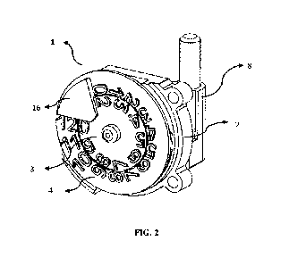
Fig. 1 shows an isometric view of an embodiment of the dispensing device.
Fig. 2 shows an isometric view of an embodiment of the event-related status
indicator
apparatus.
Fig. 3 shows an exploded view of an embodiment of the event-related status
indicator
apparatus.
Fig. 4a shows a front side isometric view of an embodiment of the first
(inner) wheel of the
event-related status indicator apparatus.
Fig. 4h shows a back side isometric view of an embodiment of the first (inner)
wheel of the
event-related status indicator apparatus.
Fig. 5a shows a front side isometric view of an embodiment of the second
(outer) wheel of the
event-related status indicator apparatus.
Fig. 5b shows a back side isometric view of an embodiment of the second
(outer) wheel of the
event-related status indicator apparatus.
Fig. 6a and 6b show different isometric views of embodiments of the base of
the event-related
status indicator apparatus.
Fig. 7 shows an isometric view of an embodiment of an actuator of the event-
related status
indicator apparatus.
Fig. 8 shows an operating cycle of an embodiment of the event-related status
indicator
apparatus at the beginning of an event registration.
Fig. 9 shows a back-side view of an embodiment of the event-related status
indicator apparatus
shown in Fig. 8.
Fig. 10 shows an operating cycle of an embodiment of the event-related status
indicator
apparatus in the middle of an event registration.
Fig. 11 shows a sectional view of an embodiment of the event-related status
indicator apparatus
shown in Fig. 10.
Fig. 12 shows an operating cycle of an embodiment of the event-related status
indicator
apparatus at the end of an event registration.
CA 03153565 2022-4-4
WO 2021/064700
PCT/1B2020/059301
PC1110907
DETAILED DESCRIPTION OF THE INVENTION
Overview / Introduction
Disclosed herein are new devices and components that are useful for indicating
the event status
of any type of event for which the event status may be desirable, such as when
event status
otherwise be unknown or difficult to determine. The apparatuses described
herein can be
classified as "components" in that they are often incorporated into or used as
part of a larger
device or system that incorporates other elements and functions, such as an
MDI device_ It
will be understood herein that any of the terms apparatus, device, and
component may be used
interchangeably herein to refer to the inventive event status identifying
machines described
herein and that any description of, e.g., a device of the invention, should be
interpreted as
providing support for a component of the invention, and vice versa.
In a specific exemplary embodiment, the invention provides new devices for
evaluating the
status of dose administration of a medical dose dispensing product, e.g.,
indicating the number
of doses dispensed or remaining available for dispensation.
The devices of the invention can be used as or in any suitable type of event
measuring product,
including any suitable type of media-dispensing or product-dispensing product,
such as those
which may be used in the food, chemical, agrochemical, or other technological
fields and can
measure any suitable aspect of an event, which may be the occurrence of an
event and/or
information about the event, such as the amount of material transported,
deposited, or removed.
Typically, an event in the context of the apparatus described herein means or
comprises the
occurrence of an event.
The inventive devices/components can be used in a number of different
applications, examples
of which are described in detail further herein. For example, devices provided
by the invention
can be used in a number of different applications, examples of which are
described in detail
further herein. For example, devices provided herein can find particular
usefulness in the field
of medicine and/or pharmaceuticals, in particular counting or indicating the
number of doses
6
CA 03153565 2022-4-4
WO 2021/064700
PCT/1B2020/059301
PCT04:194:17
dispensed from a medicine dispenser. Event indicator devices, e.g. dose
counter devices also
can find particular application in the field of propellant based pressurized
inhalation aerosols
delivered by oral and/or nasal administration systems; aqueous or non-aqueous
systems for
oral and/or nasal delivery; liquid dispensers for nasal delivery and powders
for pulmonary
administration and tablets, capsules, pellets or agglomerates for oral
administration; or pre-
filled syringes or pens or dispensers for intra-muscular or subcutaneous
delivery. Accordingly,
the event indicator devices, e_g_ dose counters, and their related devices and
methods of the
present invention can be utilized as part of these and other medicament
dispensing systems.
The devices provided herein typically will require relatively few components
as compared to
those systems previously known in the art (e.g., they may require 20 separate
components or
less, 15 components or less, 12 components, or even less than 10 components
that are involved
in the functioning of the counter). Devices of the invention also or
alternatively are capable of
registering event occurrences, magnitudes, and/or qualities, over a relatively
large event
measurement range (e.g. at least about 100 events in the case of a device that
measures
remaining events or occurred events). Devices of the invention also or
alternatively can
provide a relatively higher level of accuracy (e.g. a low false positive/false
negative dose
registration rate(s), mis-counts, or other/similar device failures) as
compared to the prior art,
particularly with respect to the functioning of the second indicator (wheel)
of the system.
Devices of the invention also or alternatively are capable existing in a
relatively compact
form/size (e.g., less than about 5 cm, less than about 4 cm, or even less than
about 2.5 cm),
and/or are relatively economical to produce as compared to previously
described devices.
A detailed description of various embodiments of the invention is provided
following a
description of principles of construction designed to aid the reader in
understanding this
disclosure.
7
CA 03153565 2022-4-4
WO 2021/064700
PCT/1B2020/059301
PC1110907
Principles of Construction
It is intended that the scope of the present disclosure should not be limited
by any particular
embodiment described herein. While various embodiments have been described
above, it
should be noted that they have been presented by way of example only, and not
limitation.
Numerous changes to the disclosed embodiments can be made in accordance with
the
disclosure herein without departing from the spirit or scope of the invention.
All headings and sub-headings are used herein for convenience only and should
not be
construed as limiting the invention in any way. The use of the terms "a" and
"an" and "the"
and similar referents in the context of describing the invention are to be
construed to cover
both the singular and the plural, unless otherwise indicated herein or clearly
contradicted by
context.
Recitation of ranges of values herein are merely intended to serve as a
shorthand method of
referring individually to each separate value falling within the range within
an order of
magnitude of the order of the range, including the endpoints (e.g., a range of
1-2 is to be
interpreted as providing support for 1.0, 1.1, 1.2, 1.3, ... 1.9, and 2.0, a
range of 10-20 is to be
interpreted as providing support for 10, 11, 12, 13, ... 19, and 20), unless
otherwise indicated
herein, and each separate value is incorporated into the specification as if
it were individually
recited herein. Unless otherwise stated, all exact values provided herein are
representative of
corresponding approximate values (e.g., all exact exemplary values provided
with respect to a
particular factor or measurement can be considered to also provide a
corresponding
approximate measurement, modified by "about," where appropriate ¨ e.g.,
disclosure of "about
10" is to be understood as also providing support for 10 exactly). Terms of
approximation,
such as "about" are used herein where measurements are understood to vary due
to
measurement issues or variability in populations, such as results of clinical
studies. The scope
of such terms will depend on the context of the element at issue and the
understanding of those
8
CA 03153565 2022-4-4
WO 2021/064700
PCT/1B2020/059301
PC1110907
skilled in the art. In the absence of such guidance in the art through
relevant teachings or
examples, "about" should be understood as meaning +1- 10% of the indicated
value(s).
As used herein, the singular form "a", "an", and "the" includes plural
references unless clearly
indicated otherwise and use of other singular forms include the plural and
vice versa. Use of
the term "or" herein is not meant to imply that alternatives are mutually
exclusive unless clearly
stated or clearly contradicted by context. In other words, "or" means "and/or"
herein, unless
expressly stated or otherwise clearly indicated.
All methods described herein can be performed in any suitable order unless
otherwise indicated
herein or otherwise clearly contradicted by context. Unless clearly indicated
or contradicted
by context the elements of a device disclosed herein can be manufactured in
any suitable
manner and by any suitable method. Unless otherwise stated or clearly
contradicted by context,
any combination of the various elements, steps, components, and/or features of
the aspects
described herein, and all possible variations thereof, are within the scope of
the invention.
The use of any and all examples, or exemplary language (e.g., "such as")
provided herein, is
intended merely to better illuminate the invention and does not pose a
limitation on the scope
of the invention unless otherwise indicated. No language in the specification
should be
construed as indicating any element is essential to the practice of the
invention unless as much
is explicitly stated. The breadth and scope of the present invention should
not be limited by
any of the above-described exemplary embodiments but should be defined only in
accordance
with the following claims and their equivalents.
The description herein of any aspect or embodiment of the invention using
terms such as
comprising", "having," "including," or "containing" with reference to a
component, element,
composition, or set of compositions, components, or elements should be
interpreted, whether
explicitly stated or not, as simultaneously providing support for a similar
aspect or embodiment
of the invention that is "mostly composed of' (or "mostly comprises"),
"consists of," or
9
CA 03153565 2022-4-4
WO 2021/064700
PCT/1B2020/059301
PC1110907
"consists essentially of," that particular element, elements, composition, or
compositions,
unless otherwise stated or clearly contradicted by context (e.g., a
composition described herein
as comprising a particular element should be understood as also describing a
composition
consisting of that element, or consisting essentially of that element, unless
otherwise stated or
clearly contradicted by context).
The term "substantially simultaneously" is used to describe two events that
occur
synchronously, that is, they take place together at about the same time, such
as the two actions
occur within about 5 seconds of one another, typically within about 2 seconds
of each other,
and usually about 1 second of one another or less, such as the two steps being
completed within
about 0.5 seconds, about 0.25 seconds, about 0.20 seconds, about 0.15 seconds,
or about 0.1
seconds or less from one another, such as within about 0.05 seconds, about
0.025 seconds,
about 0.01 seconds of one another or even less, such as within less than about
0.005 seconds
or within about 0.001 seconds of one another or less, e.g., at the same time
as one another (e.g.,
within the limits of detection).
Devices and Components Thereof
The event-status indicator devices/components of the present invention
comprise a multi-
component visual messaging system comprising two or more visual messaging
components
(e.g., indicator wheels), which are capable of and used to convey to a user
information about
current event status. Although the messaging components can operate on any
suitable basis,
typically one visual messaging component will operate upon every event to
report and usually
update the event status information and one or more second/secondary/other
visual messaging
components will operate every one or more set number of events (e.g., every
10th event) to
update the event status.
The event-status indicator device comprises a component which receives an
event signal,
energy, material, or other trigger (e.g. an "event trigger" or "trigger"), and
which initiates the
CA 03153565 2022-4-4
WO 2021/064700
PCT/1B2020/059301
PC1110907
translation of the event trigger into an event registration. The detection of
an event can be
achieved by any suitable means. An actuator component, such as those
exemplified further
herein, or actuator mean component typically is incorporated into the device
to detect the event
and transmit energy, movement, or similar force to other parts of the device
to impart
movement of the moveable components responsible for changing the status of the
status
indicators. A registerable event can be any event wherein the actuator means
or component is
not locked and the actuator means or component receives sufficient energy from
the trigger
event to impart movement of the movable components responsible for changing
the status of
the status indicators. If the actuator means or component is locked, or the
actuator means or
component does not receive sufficient energy from the trigger event to impart
movement of
the movable components responsible for changing the status of the status
indicators, the event
can be a non-registerable event.
Typically devices of the invention comprise two or more multi-component
repositionable
engagement units and two or more positioning elements to modify the position
of
repositionable engagement units upon a certain number of events, wherein two
or more
repositionable engagement units operate substantially simultaneously upon
every one or more
set number of events to modify two Of more visible messaging components to
update the event
status.
In embodiments, the actuation means initiating an event registration of the
indicator apparatus
is an actuator having an energy receiving member and an energy transfer
member, the energy
transfer member engaging with a first visual messaging component of the
indicator apparatus.
In common embodiments, the visual messaging components of the visual messaging
system
can be a first wheel and a second wheel, each comprising readable event
indicators capable of
conveying information to the user related to the current event status, the
first wheel
participating in providing the updated event status upon every event and the
second wheel
participating in providing the updated event status upon every set number of
events.
11
CA 03153565 2022-4-4
WO 2021/064700
PCT/1B2020/059301
PC1110907
In common embodiments, the multi-component engagement system also comprises
two
repositionable engagement units. In some aspects, the first repositionable
engagement unit is
designed as a stabilizing component capable of being positioned in a first,
stabilizing, position
or a second, non-stabilizing, position, preventing the second wheel from
participating in an
event registration when in the stabilizing position. In some aspects, the
second repositionable
engagement unit is designed as a driving component capable of being in a
first, non-engaged,
position and a second, engaged, position, driving the second wheel to
participate in an event
registration when in the engaged position. In some aspects, the repositionable
engagement
units are each modified from their first to their second positions by two
independent positioning
elements, each positioning element interacting with one repositionable
engagement unit to
move it from its first position to its second position. In common embodiments,
the
repositioning of the repositionable engagement units occurs substantially
simultaneously every
set number of events, e.g. every tenth event, registered by the event-status
indicator apparatus
so as to substantially simultaneously free the second wheel for rotation and
drive the second
wheel to rotate to participate in the event registration. In some aspects, the
engagement of the
two repositionable engagement units with the second wheel is performed via a
latching
mechanism present on the second wheel, in some cases this mechanism is set of
"teeth."
In common embodiments, an actuator, comprising one member to receive energy of
an event
trigger and a second member to transfer the energy of an event trigger
initiates the registration
of an event upon every event trigger. In some aspects, the element of the
actuator transferring
the energy from the event trigger is an actuator pawl, the pawl engaging with
a latching
mechanism on the first wheel, the first wheel being the recipient of the
actuation energy from
the actuator. In one embodiment the first wheel latching mechanism is a set of
teeth.
In one embodiment, the event-status indicator apparatus further comprises a
base to maintain
the first and second wheels in position relative to one another. In some
embodiments, one or
more of the repositionable engagement units and/or positioning elements is
attached to or is an
12
CA 03153565 2022-4-4
WO 2021/064700
PCT/1B2020/059301
PC1110907
integral part of the first wheel and one or more of the repositionable
engagement units or
positioning elements is attached to or is an integral part of the base.
In some embodiments, the indicator apparatus is associated with (e.g.,
contained in) a larger
device that causes, processes, modifies, measures, or otherwise is associated
with the
measurable event(s). The indicator apparatus can be, e.g., housed within a
medicament
dispenser, for example within the dispenser body of the medicament dispenser,
which may
further comprise components for storing and administering medicine to a
subject or patient
(e.g., a mouthpiece).
In some aspects, the body of the apparatus or associated device (e.g., a
medicament dispenser)
can comprise a status identifier that identifies which of the event indicators
on the first and
second wheels reflects the current event status. In one exemplary embodiment,
the device is a
medicament dispenser, such as a metered dose inhaler containing an dispenser
body for holding
a medicament container, a medicament access body in the form of a mouthpiece,
a protective
cover of the medicament access body in the form of a hinged cap, and event-
related status
indicator apparatus comprising the elements and their common or alternative
aspects and/or
embodiments as described herein, and a status identifier window in the body of
the medicament
dispenser for viewing the event status as displayed by the event-related
status indicator housed
within.
According to certain embodiments, a successful event trigger is an event
trigger comprising a
sufficient amount of energy so as to force the rotation of the first wheel of
the indicator
apparatus one increment; exemplary mechanisms for advancement are described in
detail
herein.
An event trigger can be any event capable of activating the actuator /
actuation means. The
event trigger can also or alternatively be referred to as an activation
trigger, actuation trigger,
actuation trigger event, activation event, actuation event, or simply an
actuation. The event
13
CA 03153565 2022-4-4
WO 2021/064700
PCT/1B2020/059301
PC1110907
trigger can be a mechanical trigger, such as for example a trigger caused by,
inter alia, pressing,
depressing, compressing, squeezing, twisting, turning, pulling, pushing,
pulsing, rotating either
an element of the actuator itself or a component in contact with the actuator.
Also or
alternatively, the event trigger can be the release of an associated
composition, such as the
dispensation of a chemical or medicament housed within a dispensing device
along with the
indicator apparatus. In some aspects the event trigger could be a pneumatic
pressure, such as
a blowing force or a sucking force, or similar or equivalent change in air
velocity or air
pressure. In some embodiments, an event trigger can be an energy in the form
of an electrical
signal, change in temperature, light signal, sound signal, vibrational
movement, combination
thereof, or any application of energy receivable by the actuator. Numerous
suitable examples
of such actuators are known in the art, and, accordingly, need not be
described herein in detail.
According to certain embodiments, the actuation trigger is the movement of a
medicament
container, e.g. a "squeeze" applied by the user to a device, such as an MDI,
such that a material
storage component (e.g., a medicament canister) is pushed downward, and the
event trigger is
received by the actuator as a mechanical energy of movement. According to
alternative
embodiments, other types of mechanical means operate as event triggers, such
as the pressing
of a button, tab or equivalent of a dispensing device. In one example such a
pressing of a
button, tab, or equivalent can be received by the actuator as a mechanical
force and transferred
to a mechanism which activates a needle mechanism for dispensing an injection.
In some
aspects an event trigger, the energy received from the event trigger, the
transfer of energy from
the event trigger, or any combination of the event trigger, energy receipt, or
energy transfer,
can be quick and forceful, such as may occur if the indicator apparatus is
used in auto-injection
device. In other aspects, the trigger can be a rotational trigger, such as the
twisting or turning
of an element in order to dispense a medicament. According to another aspect,
the trigger can
be an inhalation, or a sucking (negative) pressure, by a user of medicament
held within the
medicine dispenser in which the actuation means resides such as in an
embodiment wherein
the indicator apparatus is housed within a metered dose inhaler. In one
aspect, the event trigger
can be a direct trigger, such as a user directly pressing on the actuator.
According to one
14
CA 03153565 2022-4-4
WO 2021/064700
PCT/1B2020/059301
PC1110907
embodiment, the event trigger is a mechanical pressure applied to an element
of the actuation
means forcing movement of the actuation means in a linear direction.
In some embodiments the actuation means can be any actuation means capable of
receiving an
effective amount of energy from an event trigger and transferring an effective
amount of energy
from the event trigger to a component of the indicator apparatus so as to
register an event.
According to certain embodiments, the actuation of an event count is initiated
by the movement
of the first wheel of the indicator apparatus. In certain aspects the
indicator apparatus
comprises an actuation means capable of receiving an effective amount of
energy from an
event trigger and transferring an effective amount of energy from the event
trigger to the first
wheel so as to move the first wheel to an extent sufficient to register an
event.
In one aspect, the actuation means can be a mechanical means comprising one
member which
receives the energy from an event trigger and a second member which transfers
the energy
from an event trigger to a receiving element. In one aspect, the actuation
means can be an
electronic circuit, a light sensor, a temperature sensor, a sound sensor, a
movement sensor, or
any similar or equivalent sensor, component, mechanism, or system capable of
receiving an
energy from a first source and transferring that energy to a target. In some
embodiments, the
actuation means of the indicator apparatus is a mechanical means for receiving
the energy from
an event trigger and transferring the energy received from the event trigger
to the first wheel
so as to force its movement and initiate a dose registration. In some aspects,
the actuation
means is an actuator device/component, such as those exemplified and/or
described further
herein.
An actuator component ("actuator") can be a movable, mechanical element
comprising a
member capable of receiving the energy arising from one or more relevant event
or actuation
triggers, also referred to herein as the "energy receiving member", and a
member to transfer
that energy to a second component of the indicator apparatus, also referred to
herein as the
"energy transfer member". In common embodiments, the energy transfer element
transfers the
CA 03153565 2022-4-4
WO 2021/064700
PCT/1B2020/059301
PC1110907
energy from the event trigger to the first wheel. The actuator can comprise or
consist of any
suitable component, set of components, device, or system for performing these
functions.
According to one embodiment, the actuator is a plunger comprising an energy
receiving
element and an energy transfer element.
According to certain embodiments, the actuator is a part of the indicator
apparatus device.
According to alternative embodiments, the actuator is a part of the overall
system which makes
up the indicator apparatus. In some embodiments, the actuator is designed as
an element of a
dispensing device in which the remaining components of the indicator apparatus
are housed.
According to one embodiment, the energy receiving member receives or maintains
a physical
contact with a component of an associated device, such as a dispensing device.
In some
aspects, the event trigger is the actuation of that associated device. For
example, in an
embodiment where the indicator apparatus is housed within a MDI, the event
trigger can be
the squeezing of the medicament canister or dispenser housing wherein it
resides as the user
attempts to actuate the device to dispense a medicament housed therein, upon
which an element
of the medicament canister or dispensing device housing presses down on the
energy receiving
member of the actuator.
The energy receiving member of the actuator can, in some embodiments, not be
in contact with
an element of a dispensing device prior to an event trigger. In alternative
embodiments, the
energy receiving member of the actuator may be in contact with an element of a
dispensing
device prior to an event trigger, simply not receiving an actuation energy
from the element
until an event trigger occurs. Once an event trigger occurs, the energy
receiving member can
maintain contact with the component of the dispensing device throughout part
of or the entirety
of the event trigger and resulting actuation motion. Such contact can
facilitate the transmission
of the energy of an event trigger to the second component of the indicator
apparatus, e.g. the
first wheel.
16
CA 03153565 2022-4-4
WO 2021/064700
PCT/1B2020/059301
PC1110907
The energy receiving member of the actuator can be a linear rack, shaft,
plate, platfortn, tab,
boss, pin, plunger, rod, or other similar or equivalent means of receiving
energy arising from
a relevant event trigger. According to certain embodiments, the energy
receiving member of
the actuator is immobile relative to one or more other members of the
actuator. According to
alternative embodiments, the energy receiving element can move relative to one
or more other
members of the actuator.
According to common embodiments, the energy receiving member of the actuator
is a plunger,
boss, or pin, or an equivalent/similar structure used by those of skill in the
art. In some aspects,
the boss may be designed to fit within a correspondingly shaped hole in a
dispenser body. In
some aspects, the energy receiving member is a circular boss or circular pin.
In some aspects,
the boss or pin directly receives the force applied to actuator from the event
trigger. The receipt
of this trigger can begin the set of activities required to register an event
on the indicator
apparatus.
The receipt of energy from an event trigger by the energy receiving member can
move the
actuator in any suitable direction, such as in a substantially or essentially
entirely linear
direction. According to some embodiments, the linear axis upon which the
actuator travels,
which may also be referred to as the axis of actuation, is in line with or
intersects the linear
axis upon which the first and second wheels rotate. According to alternative
embodiments, the
linear axis upon which the actuator moves does not intersect the longitudinal
axis upon which
the first and second wheels rotate. In one embodiment, the linear axis upon
which the actuator
moves is offset to the longitudinal axis upon which the first and second
wheels rotate. That is,
upon actuation, in response to the receipt of energy from an event trigger by
the boss or pin,
the actuator moves in a linear direction along an axis offset to the
longitudinal axis upon which
the first and second wheels rotate. In some aspects, the device comprises an
axis of actuation
offset from the longitudinal axis of rotation of the first and second wheels
which results in a
detectable torque, which according to certain aspects detectably aids in the
registration of an
event by movement of one or more event-registering components of the system,
and, according
17
CA 03153565 2022-4-4
WO 2021/064700
PCT/1B2020/059301
PC1110907
to more particular aspects, is a sufficient amount of torque to be applied to
the element of the
indicator apparatus receiving the actuation energy from the actuator, e.g. the
first wheel, for it
to register an actuation under appropriate conditions.
In one aspect the actuator comprises one or more members capable of
transferring the energy
received from an event trigger to a second element of the indicator apparatus.
An energy
transfer member can have any size, shape or design capable of cooperating,
communicating,
or otherwise interacting with or engaging a second component of the indicator
apparatus. In
one embodiment, the first wheel of the indicator apparatus is the recipient or
target of the
energy transfer.
An energy transfer member/component can be mechanical means of engaging with a
second
component of the indicator apparatus. For example, the energy transfer member
can be an
artn, tab, ridge, clip, catch, notch, pawl or similar elements or any
combination of such
elements which function to transfer energy arising from a relevant event
trigger of the second
component of the indicator apparatus via the actuator. In some aspects, the
energy from an
event trigger can be transferred to the second component via a mechanical
engagement.
The energy transfer member can be designed to have a shape complementary to
the component
of the indicator apparatus to which it transfers energy. In one embodiment,
the actuator energy
transfer member is a pawl. The actuator pawl can be a latch-like device
designed to engage
with the first wheel of the indicator apparatus.
The energy transfer member, e.g. actuator pawl, can be attached to the
actuator at one end and
free at the opposite end, such as e.g. in an ann design. Such a configuration
creates a movable,
flexible, in some aspects spring-like design, allowing the actuator pawl to
bend or flex slightly
in response to pressure. The free end of the actuator pawl can be free to
engage with other
indicator apparatus components, such as the first wheel to transfer an
actuation force.
18
CA 03153565 2022-4-4
WO 2021/064700
PCT/1B2020/059301
PC1110907
An energy transfer member, e.g., an actuator pawl, can comprise a "catch"
element at its free
end which can further facilitate the engagement with or directly engage with
the indicator
apparatus component receiving the energy transfer. The catch on the free end
can have a
specific shape or comprise an element such as a knob, bump, notch, protrusion,
latch, tooth, or
similar or equivalent shape which cooperates, interacts, or engages with
another device
component. In some aspects, the device component with which it interacts can
have a
complementary shape. According to one embodiment, the actuator of the
indicator apparatus
of the present invention comprises an actuator pawl which further comprises a
catch in the
form of one or more fixed teeth, a distinct shape at its end which protrudes
outward from the
end of the actuator pawl resembling a latch "tooth" (e.g. having a square-,
rectangular-,
triangular-, trapezoidal-, or polygonal-shape which aids the actuator pawl in
the engagement
of the actuator component with a second component).
In one embodiment, the actuator comprises a pawl with a catch in the form of a
fixed tooth
which engages with the indicator apparatus first wheel. The actuator pawl
fixed tooth can be
in the form of a ratchet tooth which can engage with a complementary ratchet
tooth latching
mechanism of the first wheel, described elsewhere herein. The actuator pawl,
having a catch,
e.g. a fixed ratchet tooth, provides the mechanism for the actuator's
engagement with the first
wheel to facilitate the event trigger energy transfer. The first wheel can be
designed to
cooperate, communicate, interact, or otherwise engage with the actuator, e.g.
the fixed ratchet
tooth of the actuator pawl, for example having one or more complementary
receiving areas for
the fixed ratchet tooth of the actuator pawl which again is described
elsewhere herein.
The energy transfer member can be an integral element of the actuator, the
energy transfer
member being manufactured as part of the actuator (e.g. as a single element).
Alternatively,
the energy transfer member can be manufactured as a separate component from
the actuator
and later fastened to the actuator by way of glue, a tongue-and-groove
fastening mechanism,
screws, clips, snap fit, heat staking or heat welding or other means of
attachment to the actuator
pawl_ Further, the catch mechanism can be an integral element of the energy
transfer member,
19
CA 03153565 2022-4-4
WO 2021/064700
PCT/1B2020/059301
PC1110907
the catch mechanism being manufactured as part of the energy transfer member
(e.g. as a single
element). Alternatively, the catch mechanism can be manufactured as a separate
component
from the energy transfer member, being later fastened to the energy transfer
member by way
of glue, a tongue-and-groove fastening mechanism, screws, clips, snap fit,
heat staking or heat
welding, or other means of attachment to the energy transfer member.
According to one embodiment, the actuator receives energy from an event
trigger from one
direction and transfers it in a second direction. In some embodiments, the
first (trigger-applied)
and second (transferred) directions can be the same, e.g. the same linear
direction. In some
embodiments, the first and second directions can be different directions. Also
or alternatively,
the actuator can be designed such that it is capable of transferring the
actuation energy in a
second direction that is substantially or actually perpendicular to the
direction from which the
actuation energy was received. In other embodiments, the actuator transfers
the energy in the
same or substantially the same direction as it is received. The transfer of
the energy can in
either case cause an indicator, such a wheel, to move in any suitable
direction with respect to
the direction of transfer_
For example, according to certain embodiments, the indicator apparatus
includes the operation
of the actuator means, e.g. an actuator as described previously, receiving
energy from an event
trigger in the form of a motion and transferring that motion to a second
element of the indicator
apparatus. In some aspects, the motion of the actuation or event trigger is a
substantially,
essentially, or entirely rectilinear motion. In other aspects, the motion of
the actuation or event
trigger is a rotational motion, such as the type of motion used to open a
bottle or turn a knob
or valve so as to provide a release or disengagement of elements or
dispensation of a substance
or composition held within.
In some embodiments, rectilinear motion of an actuator or event trigger is
converted to a
rectilinear motion of the actuator. In some embodiments, the rectilinear
motion of the event
trigger is converted to a rotational motion of the actuator_ In one
embodiment, the rectilinear
CA 03153565 2022-4-4
WO 2021/064700
PCT/1B2020/059301
PC1110907
motion of the event trigger is received as energy of motion and causes a
rectilinear motion of
the actuator which is then transferred to a second component of the indicator
apparatus to cause
a rotational motion of the second (receiving) component of the indicator
apparatus. In further
embodiments, an event trigger in the form of rotational motion, e.g. a
twisting or turning such
the operation of a screw mechanism of, e.g. a dispensing device in which the
indicator
apparatus is housed is mechanically converted to rectilinear motion of the
actuator which is
further transferred to the transferred energy receiving component causing
rectilinear motion or
rotational motion of the receiving component. Irrespective of the direction
from which energy
is received by the actuator energy receiving member or to which the energy is
transferred by
the actuator energy transfer member, the receipt and transfer of the energy
from a trigger event
typically instigates movement of the indicator and, accordingly, a change in
event indication
status.
Event-related status indicators are designed to register the occurrence of
multiple events.
Therefore, the design of an event-related status indicator can benefit from
the incorporation of
a means to re-set the actuation means such that it may be re-set upon
conclusion of an event
and re-actuated upon (he next event. In a circumstance wherein the actuation
means does not
become re-set and available for re-actuation, the indicator apparatus could
not be re-actuated
and therefore could not register subsequent events if/as they occurred. This
may be a beneficial
design option for the end of an event registration cycle, such as, for
example, in an embodiment
wherein the indicator apparatus is housed with an medicament dispenser, the
dispensation of a
dose of medicament being the events registered, when insufficient medicament
remains in a
medicament container to administer a full dose. In such a case, an inability
to actuate the
medicament dispenser due to the actuation means not being in a position for re-
actuation can
be or contribute to a signal to the user that the medicament has been
exhausted.
According to certain embodiments, the actuation means or actuator includes or
is accompanied
by one or more mechanisms to assist, direct, guide, be completely responsible
for or is
otherwise capable of returning the actuator means to a start position after an
actuation has
21
CA 03153565 2022-4-4
WO 2021/064700
PCT/1B2020/059301
PC1110907
occurred. According to certain embodiments, the mechanism for returning the
actuator back
to a starting position can be any means capable of returning the actuation
means to a starting
position. For example, the return means could be a flex arm, flex tab,
flexible and/or
compressible material element such as sponge, foam, rubber or other material
capable of being
depressed and returning to a start position after depression or compression,
an inflatable
element again capable of being depressed and returning to a start position
after depression or
compression, or such a similar or equivalent element.
In one embodiment, the mechanism for returning the actuator back to a starting
position is a
spring. In some aspects, the actuator has an arrangement to attach a spring to
assist the return
movement of the actuator after actuation/activation or operation. The spring
can be attached to
actuator. The spring can also or alternatively be attached to a dispenser
body. Also or
alternatively, the spring can be attached to both a dispenser body and the
actuator. One or
more elements which return the actuator to a start position after each
actuation can be
manufactured as part of a dispenser body, part of the actuator, part of both
the dispenser body
and the actuator, or as an independent element The one or more elements can be
manufactured
from the same one or more materials as any one or more of the materials of
which the indicator
apparatus or dispenser components are manufactured. Also and alternatively,
the one Of more
elements can be manufactured of one or more materials different from the one
or more
materials used to manufacture the indicator apparatus or dispenser. For
example, the indicator
apparatus and/or dispenser in which it may be housed can be manufactured from
one or more
hard polymers and the element assisting, directing, guiding, being completely
responsible for,
or otherwise capable of returning the actuator to a start position after an
actuation has occurred
can be made of a metal, e.g. as in a metal spring.
The means for returning the actuator to a starting position can act upon a
manual trigger or
automatically at the end of an actuation event. For example, actuation of the
actuator could be
similar to the ejection of a pen tip in a retractable pen wherein the "event
trigger" is the
depression of the plunger on a pen which forces the tip of the pen out from
the pen housing so
22
CA 03153565 2022-4-4
WO 2021/064700
PCT/1B2020/059301
PC1110907
as to enable its use. A manual means of resetting the indicator apparatus can
be a reset switch
or button such as, for example, those which can be pressed on the body of a
retractable pen so
as to retract the tip and return it to the inside of the pen housing when the
user is finished with
the pen. Alternatively, the means for returning the actuator to a starting
position can be an
automatic mechanism, such that upon the completion of an actuation, unless
otherwise
restricted from doing so, the actuator utilizes a stored energy, e.g. a
compression energy created
by the depression of a spring during an actuation stroke, to automatically
return the actuator to
its starting position.
According to certain embodiments, the means for assisting, directing guiding,
being
completely responsible for, or otherwise capable of returning the actuation
means to a start
position after an actuation has occurred can operate cooperatively with the
indicator apparatus
such that in circumstances wherein the indicator can become locked (e.g. when
housed within
a medicament dispenser and the medicament container has no remaining full
doses of
medicament and also or alternatively when the indicator apparatus has reached
its lowest or
highest count, also described as the indicator apparatus having reached the
end of its life cycle),
the means for returning the actuation means to its starting position may be
inhibited, such that
the actuation means remains in a depressed or otherwise activated position,
does not return to
a start position, and therefore cannot be re-activated. In such a manner, a
dispensing device in
which an indicator apparatus may be housed can be adapted to prevent the
dispensing device
from being actuated after a predetermined number of events, e.g.
dispensations, have been
registered. According to certain embodiments, this may be the case when the
medicament
dispenser is fully exhausted (e.g. empty or otherwise inoperable).
According to one embodiment, an energy transfer element, e.g., an actuator
pawl, is capable
of "riding over," or passing over, or otherwise not engaging (or at least not
movingly engaging)
with the latching mechanism (e.g., teeth) of the energy receiving component,
e.g. the first
wheel in at least certain events/times during actuations. According to one
embodiment, as the
actuator is returned to its original position by the incorporated return
mechanism, the actuator
23
CA 03153565 2022-4-4
WO 2021/064700
PCT/1B2020/059301
PC1110907
pawl fixed ratchet tooth can slide over the element with which it engaged on
the actuation of
the actuation means (e.g. the first wheel latching mechanism), such that it
returns to a start
position while not further engaging with the first wheel latching mechanism so
as to cause
further rotation of the first wheel while doing so. The actuator can then
complete the actuation
stroke, placing the first and or first and second wheels in position of having
completed a single
increment of rotation, the details of which are discussed elsewhere herein.
Hence the fixed
ratchet tooth (exemplary of catch element on an energy transfer member of the
actuator
intended to engage with a second component, e.g. the teeth on the first wheel
of the indicator
apparatus) can be shaped such that a first side has a shape complementary to a
first side of the
element with which it is intended to engage (e.g. a complementary clip or
latch shape), while
the second or opposing side can have a shape which facilitates the sliding of
the one component
over the other (e.g. the fixed tooth of the actuator pawl over the ratchet
tooth of the first wheel)
as is commonly understood as a ratchet mechanism. Such a shape may be, for
example, an
angled or rounded edge or side. Additionally, the component with which it
engages, for
example the ratchet tooth or teeth of the first wheel, can have a shape on a
first side that is
complementary to the first side of the, e.g. fixed ratchet tooth and a shape
on the opposite side
which further facilitates the sliding of the one component over the other
(e.g. the actuator pawl
fixed tooth over the first wheel ratchet tooth). According to such a design,
when in motion
(caused by an actuation trigger) in a first actuation/activation direction
(e.g. downward), the
complementarily-shaped side of the fixed ratchet tooth on the actuator pawl
being engaged
with the second element of the indicator apparatus (e.g. first wheel ratchet
tooth) imparts an
energy to that element and forces it to move, for example forcing the first
wheel to rotate.
When the actuation trigger is complete and the actuation means is in motion to
its return
position (e.g. a direction opposite that of its initial activation direction,
for example upward),
the actuator pawl fixed ratchet tooth disengages with the previously-engaged
ratchet tooth of
the first wheel, the fixed tooth rides over an adjacent ratchet tooth while
the first wheel remains
stationary, and reengages with the next ratchet tooth once the actuation means
has returned to
its original or starting position such that it is in position to rotate the
first wheel upon the next
24
CA 03153565 2022-4-4
WO 2021/064700
PCT/1B2020/059301
PC1110907
actuation initiated by an event trigger and the first wheel or first and
second wheel as will be
described elsewhere herein, have completed a single increment of rotation.
In some aspects, the device comprises an actuation energy transfer component
and a first wheel
latching mechanism which together are configured and/or operate as a ratchet
mechanism,
which both facilitates registration of an event and also inhibits or prevents
rotation of the inner
wheel in an opposite direction from the direction associated with registering
additional events.
For example, an actuator pawl fixed ratchet tooth and a ratchet-tooth latching
mechanism on
the first wheel are configured so as to detectably inhibit or prevent (under
normal operating
conditions) reverse rotation of the inner wheel. According to certain
embodiments, as the
actuator pawl fixed ratchet tooth disengages from the ratchet tooth of the
latching mechanism
on the first wheel after receipt of an actuation energy, the actuator pawl
fixed tooth can "slide"
or "ride" over an adjacent ratchet tooth of the first wheel latching mechanism
(or otherwise
move over or along without engaging in a manner that causes a movement
associated with
event registration or reverse rotation of the first wheel). Such "sliding", or
"riding", of the
actuator pawl fixed ratchet tooth over a first wheel ratchet tooth can allow
for the actuator to
return to a start position (or next position) such that it is capable of
receiving and reacting to a
new actuation or subsequent actuation energy while not sufficiently engaging
with the first
wheel so as to cause it to rotate in a reverse direction. The shape of the
actuator pawl fixed
ratchet tooth, and the shape of the ratchet tooth of the latching mechanism on
the first wheel
can be such that while the actuator is traveling in a direction toward its
starting position, there
is no component of the actuator pawl fixed ratchet tooth shape which can
engage (or at least
movingly engage) with the ratchet tooth on the first wheel over which it
slides or rides to an
extent sufficient to force the first wheel to rotate. According to some
embodiments, the reverse
rotation of the first wheel is prevented by use of a ratchet mechanism.
According to some
embodiments, the reverse rotation of the first wheel is prevented by use of a
ratchet mechanism
alone. According to alternative embodiments, the reverse rotation of the first
wheel is
prevented by use of a ratchet mechanism in conjunction with one or more
secondary means of
preventing undesirable rotation of the first wheel, such as for example but
not limited to the
CA 03153565 2022-4-4
WO 2021/064700
PCT/1B2020/059301
PC1110907
engagement of the second wheel catch mechanism on the flex drive arm of the
first wheel and
the latching mechanism of the second wheel as is described elsewhere herein.
According to certain embodiments, in its resting, starting, next, or original
position, e.g. prior
to an actuation or upon the completion of an actuation, the actuator pawl
fixed tooth and the
space between ratchet teeth of the first wheel latching mechanism, can
comprise shapes such
that the actuator pawl fixed tooth "nests", or fits complementarily within the
space between
the ratchet teeth of the first wheel latching mechanism. Such a complementary
fit between
such components can, e.g., provide a means of preventing or a least detectably
inhibiting the
first wheel from rotating in either direction while in a resting position,
both sides of the actuator
pawl fixed tooth making sufficient contact with, or capable of making
sufficient contact with,
sides of first wheel latching mechanism ratchet teeth above and below the
actuator pawl fixed
tooth so as to block the first wheel from inadvertent rotation in either
direction.
The first wheel can comprise design elements that allow it to cooperate,
communicate, interact
or otherwise engage with other components of the indicator apparatus. Such
elements can
comprise a latching mechanism (e.g. a first set of teeth), a means, mechanism
or element for
engaging with the second wheel, and an element capable of causing a
modification of position
of a base element. Each design element of the first wheel can further comprise
varying
additional elements aiding in its functionality which will be described
further herein.
The first wheel can have generally a disc, ring, or circular shape. According
to certain aspects,
a first face of the first wheel can comprise elements which all lie on or
substantially on the
same plane, having no raised or depressed areas that vary significantly from a
single plane (or
that vary from the surface by less than about 15%, less than about 10%, or
less than about 5%
of the thickness of the surface). According to alternative aspects, a first
face of the wheel may
comprise elements such as a raised inner or outer edge, lower inner or outer
edge, or raised,
embossed, carved or etched communication elements such as event indicators as
to the status
26
CA 03153565 2022-4-4
WO 2021/064700
PCT/1B2020/059301
PC1110907
of doses available in the medicament dispenser. Such communication elements
will be
described further elsewhere herein.
According to aspects a second side of the first wheel can comprise elements
which protrude
from the second side so that the elements do not all lie substantially within
the same plane.
For sake of orientation, as used herein the "front" side or face of the first
wheel is the side or
face comprising event indicators (visual communication elements), to be
described elsewhere.
The "back" side or face of the first wheel is the side or face comprising the
latching mechanism
and does not comprise event indicators.
According to embodiments, the element of the first wheel capable of and
designed for receiving
the actuation energy from the actuator means is a latching mechanism. The
first wheel latching
mechanism can be any mechanism capable of engaging with another element of the
indicator
apparatus, such as for example the energy transfer member of the actuator, or
even more
specifically, such as a catch on the energy transfer member of the actuator,
Such a mechanism
can be, for example, one or more insets or one or more protrusions shaped to
receive, interact,
cooperate or engage an element with a complementary shape. In one aspect, the
first wheel
latch mechanism is a first set of teeth. In one aspect this set of first wheel
teeth can comprise
a number of ratchet teeth.
As used herein, the term "ratchet tooth" or "ratchet teeth" is a tooth or set
of teeth shaped such
that they cooperatively engage with and receive a first force or motion
causing a rotation of
the element on which they reside in one direction, however their shape allows
them to resist or
avoid rotation in an opposite direction upon a second force or return motion.
Ratchet teeth can
be of any suitable size or shape, such as rectangular, square, triangular or
pyramid shaped,
semi-circular, oblong, or squircular shape, or have any type of trapezoidal,
polygonal, or any
shape which can interact with another element of the mechanism having a
complementary
shape or any shape capable of interacting with a tooth having such a
structure, yet capable of
27
CA 03153565 2022-4-4
WO 2021/064700
PCT/1B2020/059301
PC1110907
resisting, deflecting, or avoiding receiving or reacting to a force or motion
upon a return motion
of an interacting element. Such ratchet teeth can have a complementary shape
to a fixed ratchet
tooth of an actuator pawl.
According to one embodiment, the actuator pawl rides over, or passes over, or
otherwise does
not engage with the latching mechanism of the first wheel (e.g. first wheel
first set of teeth)
when the dispensing device is returning to the original or non-dispensing
position. Further, as
will be described elsewhere herein, the engagement of the second wheel catch
mechanism on
the flex drive arm of the first wheel and the latching mechanism of the second
wheel prevent
reverse rotation of the first wheel when the driver is returning to its
original or non-dispensing
position. According to some aspects, once the actuator pawl has returned to
its original
position after an actuation, or also or alternatively when the actuator pawl
is in its original or
starting position prior to an actuation, the latching mechanism design of the
actuator pawl fixed
tooth and the ratchet tooth design of the latching mechanism of the inner
wheel provide
additional means of preventing rotation of the first wheel, as the
complementary design of the
elements of the latching mechanism mechanically prevents or at least
detectably inhibits
undesirable first wheel rotation (e.g., rotation in a direction that is
opposite the direction
associated with registering the next event).
According to one embodiment, the engagement of the actuator pawl fixed ratchet
tooth with
the first wheel latching mechanism, e.g. ratchet teeth, transfers the event
trigger actuation
energy from the actuation means (e.g. actuator) to the first wheel, driving
the first set of teeth
on the first wheel and causing the first wheel to rotate. The first wheel
first set of teeth can
have any number of teeth, such as 1 to greater than 100 teeth, more commonly 5
to 50 teeth,
even more commonly 10 ¨ 20 teeth. In one embodiment, first set of teeth on the
first wheel
has 10 teeth.
The first wheel latching mechanism is positioned so as to be accessible to,
and can be in contact
with, the energy transfer member of the actuator. More specifically in a
demonstrative
28
CA 03153565 2022-4-4
WO 2021/064700
PCT/1B2020/059301
PC1110907
embodiment, the teeth of the first wheel are positioned so as to be accessible
to, and in contact
with, the actuator pawl, even more specifically being in contact with the
actuator pawl catch
mechanism (e.g. fixed ratchet tooth). The first wheel can comprise ratchet
teeth arranged on
its surface.
More specifically, according to certain embodiments, the teeth of the first
wheel are ratchet
teeth which are arranged on a boss. As used herein, a "boss" is a protruding
feature. As an
element of the actuator, a boss is an element that protrudes outward from the
actuator and,
according to certain embodiments, can function as an energy receiving member
to receive
energy from an event trigger. As an element of the first wheel, a boss is an
element which can
protrude from the back of the first wheel. The first wheel boss can be
circular, polygonal,
tubular, or cylindrical in shape and can be centrally located within the first
wheel. The first
wheel boss can have an opening therethrough which defines the center of both
the boss and the
first wheel as a whole.
The diameter of a boss can be smaller than the outer diameter of the first
wheel. According to
some embodiments, the diameter of the boss is at least 10% smaller than that
of the outer
diameter of the first wheel, such as for example at least 10% smaller, at
least 15% smaller, at
least 20% smaller, at least 25% smaller, at least 30% smaller, at least 35%
smaller, at least
40% smaller, at least 45% smaller or even greater, such as approximately 50%
smaller, at least
55% smaller, at least 60% smaller, at least 65% smaller, or at least 70% or
75% smaller or even
more. According to some embodiments as will be further described herein, the
first set of teeth
of the first wheel may be incorporated into or onto this central boss. The
boss can be centrally
located on the wheel (i.e., can be a central boss). Accordingly, as in some
embodiments the
first wheel first set of teeth receive the actuation force from the actuator
and hence cause the
first wheel to rotate, the diameter of the central boss, and the size of the
first wheel teeth therein
or thereon may dictate the rotational distance covered by a single increment
of rotation of the
first wheel.
29
CA 03153565 2022-4-4
WO 2021/064700
PCT/1B2020/059301
PC1110907
A boss can aid in securing the first wheel within the base, an element of the
indicator apparatus
to he described elsewhere herein. The base, as described elsewhere, can have a
hole, e.g., a
hole in its center. Such a hole can be designed in shape such that it can
receive a boss of the
first wheel, such that the first wheel can nest or sit within the base. Such a
configuration can
aid the various elements of both the first wheel and base, to align,
communicate, cooperate,
interact, or engage with one another as is required for successful operation
of the indicator
apparatus_
According to some embodiments, the first wheel comprises a circular boss,
protruding from
the back of the first wheel, such boss designed to fit smoothly yet securely
within a
cooperatively sized and shaped hole within the base, so as to provide means
for the first wheel
to sit or nest within the base, while being free to rotate within the base
unless otherwise
impeded, the boss further comprising the first wheel latching mechanism toward
its far end
which extends through the hole in the base such that the latching mechanism is
accessible to
the energy transfer member of the actuator. The first wheel first set of teeth
can protrude from
the end of the central boss so as to define the end of the central boss or
alternatively can be
arranged so as to extend above and around the circular boss. According to a
different design
the teeth can be carved into, or out of, the central boss so as not to add
additional height or
thickness to the central boss yet provide for the teeth to be in the outer,
circumferential surface
of the boss. According to certain embodiments, the first wheel comprises a
circular boss
protruding from the back side of the first wheel, the circular boss further
comprising a first set
of teeth having a ratchet design, the ratchet teeth positioned at the end of
the circular boss, and
further the ratchet teeth having a polygonal shape of complementary shape to
that of a fixed
ratchet tooth on the actuator pawl, such that the actuator pawl ratchet tooth
can fit securely
within any one ratchet tooth of the first wheel.
A boss can be constructed within the first wheel such that the first wheel
comprising the boss
is a single unit. Alternatively, a boss can be manufactured as a separate unit
and attached (e.g.
CA 03153565 2022-4-4
WO 2021/064700
PCT/1B2020/059301
PC1110907
by screws, glue, clips, tongue-and-groove, snap fit, heat staking or heat
welding, or other
similar or equivalent fastening mechanisms) to the back side of the first
wheel.
In some aspects, the first wheel is capable of rotation, e.g. in a clockwise
or counterclockwise
direction. In some aspects, when free of any impediment, the first wheel is
capable of rotation
in both a clockwise and a counterclockwise direction. The first wheel can
encounter
impediments, such as interaction with other components of the indicator
apparatus, which can
impede its rotation in a certain direction, forcing a capability to only
rotate in a single direction
under certain circumstances as will be further detailed herein. In some
aspects, the first wheel
can further be provided with a central bore or hole. According to certain
embodiments, the
central bore or hole can act as a bearing for the central axis of the
indicator apparatus, about
which the one or more wheels of the indicator apparatus can rotate. In some
aspects, the
central bore or hole can facilitate mounting or securing the indicator
apparatus within or to a
larger device, e.g. a medicine dispenser. For example, the larger device body
can have a pin,
shaft, boss, or other similar or equivalent structure capable of fitting
within the central bore or
hole of the first wheel in such a manner that the inner wheel can slide over
the structure,
structure then serving to hold the inner wheel in position relative to the
larger device,
maintaining its position without impeding the rotation of the inner wheel when
the inner wheel
is called upon to rotate under certain conditions. In some embodiments, such a
mounting
support can be the sole mounting mechanism. In some embodiment, such a
mounting support
can be in addition to other mounting supports, such as those provided by
mounting elements
present on a base component of the indicator apparatus.
The event-related status indicator apparatus of the present invention can
further comprise a
means for intermittently or after a set number of events, engaging the second
wheel to drive its
rotation in conjunction with the first wheel. Such a driving means can be any
means, e.g. any
unit, element, or component capable of being in a position to interact with,
contact, or
otherwise engage with, or be disengaged from, the second wheel and is movable
from one
position to another. For example, the means can be a repositionable arm, a
selective switch, a
31
CA 03153565 2022-4-4
WO 2021/064700
PCT/1B2020/059301
PC1110907
movable hook, catch, latch, or other similar or equivalent mechanism for
engaging or
disengaging the second wheel according to certain conditions and when engaged,
drive its
rotation.
In some aspects, the event-related status indicator apparatus can comprise two
repositionable
engagement units, each engaging the second indicator wheel, however each
engaging the
second indicator wheel to perform a different function_ Repositionable
engagement units can
be elongated members_ The repositionable engagement units can be fixed, e.g.
immobile, on
one end and movable on a second end. According to one embodiment, the means
for engaging
the second indicator wheel so as to drive its rotation is one of the
repositionable engagement
units of the indicator apparatus.
In embodiments the repositionable engagement unit which engages the second
wheel under
certain conditions is a repositionable or flexible arm attached to the first
wheel. According to
embodiments, the flexible arm responsible for driving the second wheel is the
only arm on the
first wheel; that is, the first wheel does not contain or is not bound to more
than one flexible
drive arm. Such an element may be referred to as a repositionable engagement
unit, the second
(of two) repositionable engagement units, the "flexible drive arm" or the
"flex drive arm",
"drive" indicating that the function of the element is to intermittently, e.g.
after a set number
of events, engage the second wheel so as to share the energy of rotation of
the first wheel with
the second wheel and to "drive" its rotation in conjunction with the first
wheel.
In one aspect, the flex drive arrn can be attached to or part of the first
wheel. In some
embodiments, the flex drive arm can be manufactured as a separate component
and fastened
onto the first wheel so as to facilitate its function, such as by glue,
screws, tongue and groove,
snap fit, heat staking or heat welding, or other similar or equivalent
mechanism capable of
achieving such an attachment_ For example, a separate flex drive arm may have
a tongue
element capable of sliding into and along a groove in the surface of the first
wheel such that
the two elements may be fastened together. Alternatively, the first wheel flex
drive arm may
32
CA 03153565 2022-4-4
WO 2021/064700
PCT/1B2020/059301
PC1110907
be heated and melted onto the first wheel. An advantage of the first wheel
flex drive arm being
integral to the main body of the first wheel is that it reduces the number of
total components
of the indicator apparatus and prevents the need for any type of fastening
mechanism which
could fail or otherwise interfere with the cooperation of multiple components.
In one aspect,
it may be useful to manufacture the flex drive arm as a separate component so
as to facilitate
slightly different positioning such that it allows a particularly designed
indicator apparatus to
fit within a defined space of a specific dispensing device.
The repositionable engagement unit intermittently engaging the second wheel
can be a first
wheel flex drive arm arranged annularly, or circumferentially, about the first
wheel. The first
wheel flex drive arm can be an arm, fastened at one end to the first wheel,
but that protrudes
freely from or separate from the first wheel at its opposite end. In one
embodiment, the first
wheel flex drive arm can extend from the side of the first wheel such that it
remains in the same
plane of the first wheel. In an alternative embodiment, the first wheel flex
drive arm extends
from the side of the first wheel but is torqued, twisted, or otherwise
designed such that part or
all of the first wheel flex drive arm from the point of attachment to the free
end of the first
wheel flex drive arm raises above, or falls below, the plane of the first
wheel.
The repositionable engagement unit, when embodied as a first wheel flex drive
arm arranged
annularly about the first wheel, can be arranged such that from the point of
its attachment to
the first wheel to the tip of the arm, its length represents at least 1% of
the overall circumference
of the first wheel. That is, the amount of the overall circumference of the
first wheel
represented by the length of the first wheel flex drive arm can be at least
1%, at least 3%, at
least 5%, at least 10%, at least 15% or in some aspects more, such as at least
approximately
20%, at least approximately 25%, at least approximately 30%, at least
approximately 35%, at
least approximately 40%, at least approximately 45%, or at least approximately
50% of the
overall circumference of the first wheel. According to one embodiment, the
length of the first
wheel flex drive arm represents between about 5% and 50% of the total
circumference of the
33
CA 03153565 2022-4-4
WO 2021/064700
PCT/1B2020/059301
PC1110907
first wheel, such as about between 10 and about 45% or about 15 to about 40%
of the total
circumference of the first wheel.
The repositionable engagement unit responsible for intermittently, e.g. upon a
certain number
of events, engaging with the second wheel can be arranged within the indicator
apparatus such
that upon a set number of actuations or events, it engages with a positioning
element which
diverts the repositionable engagement unit from one path of motion to a second
path of motion,
the second path of motion being one in which the first wheel flex drive arm
engages the second
wheel.
A repositionable engagement unit can be a first wheel flex drive arm designed
to engage with
a positioning element on the base, the positioning element blocking a first
path of motion of
the first wheel flex drive arm and forcing a second path of motion of the
first wheel flex drive
artn, the second path of motion being one in which the first wheel flex drive
arm engages with
the second wheel. The repositionable engagement unit responsible for driving
the rotation of
the second wheel can remain disengaged from the second wheel unless it comes
into contact
with the positioning element of the base, such contact occurring only upon a
set number of
events. According to aspects, the set number of events is every 10th event.
According to certain embodiments, to further facilitate the engagement of the
repositionable
engagement unit responsible for driving the rotation of the second wheel with
the second
wheel, the repositionable engagement unit further comprises a catch. A "catch"
can be any
type of wheel engagement element, such as one or more protrusions of any kind,
e.g. a tab,
knob, bump, tooth, or other such mechanism capable of being received by a
complementary
recession in one or more cooperating element(s). According to certain
embodiments, the wheel
engagement element or catch element of the repositionable engagement unit
responsible for
driving the rotation of the second wheel comprises one or more teeth.
According to one
embodiment, the wheel engagement element is a "driver catch", or second wheel
driver tooth
located on the flex drive arm of the first wheel.
34
CA 03153565 2022-4-4
WO 2021/064700
PCT/1B2020/059301
PC1110907
According to certain embodiments, a flex drive arm of the first wheel drives
the second wheel
through engagement of the second wheel driver tooth with a latch mechanism on
the second
wheel. The latch mechanism of the second wheel can be a second wheel second
set of teeth.
The catch mechanism of the repositionable engagement unit responsible for
driving the second
wheel, e.g. the second wheel driver tooth, can have a rectangular, square,
triangular or pyramid
shape, a semi-circular, oblong, squircular shape, or have any type of
trapezoidal, polygonal, or
similar or equivalent shape which interacts with another element of the
apparatus having a
complementary shape or any shape that interacts with, e.g. a tooth of the
second wheel latching
mechanism having such a complementary structure. According to common
embodiments, the
second wheel driver tooth has a polygonal shape designed to be complementary
to the shape
of the second wheel latching mechanism, which can be, as will be described, a
second set of
teeth.
In some aspects the catch mechanism of the repositionable engagement unit
responsible for
driving the second wheel (e.g. a second wheel driver tooth on a flex drive arm
attached to the
inner wheel), can make a relatively loose contact with the latching mechanism
on the second
wheel, (e.g. the second wheel second set of teeth), upon every actuation, even
when not being
fully engaged with the latching mechanism such as that which occurs upon every
set number
of events. Such a relatively loose contact can be defined as contact
sufficient to aid in holding
or hold the inner wheel in a position preventing inadvertent rotation unless
forced to rotate via
an actuation (e.g. unless acted upon to rotate as driven by a trigger event),
but that is not strong
enough to prevent rotation of the first wheel independent of the second wheel
during an
actuation, as is the case for every actuation except for those wherein the
repositionable
engagement unit responsible for driving the second wheel, (e.g. flex drive
arm) interacts with
a positioning unit on the base forcing engagement of the unit with the second
wheel latching
mechanism and causing rotation of both the first and second wheels.
A catch on the repositionable engagement unit responsible for driving the
second wheel, e.g.
the second wheel driver tooth of the flex drive arm on the first wheel, aids
in the stabilization
CA 03153565 2022-4-4
WO 2021/064700
PCT/1B2020/059301
PC1110907
of the first wheel, preventing its rotation when rotation is not needed or
desired for accurate
operation of the device.
A first wheel can further comprise an element which, under certain conditions,
e.g. upon a
certain number of events, makes contact with a repositionable engagement unit
responsible for
stabilizing the second wheel, to be described elsewhere herein, to modify its
position. In one
aspect, the element which can modify the position of the base flexible arm is
a positioning
element. A positioning element can be a deflector (which may be called a first
wheel
deflector).
The purpose of the positioning unit located on the first wheel, e.g. a first
wheel deflector, is to
intermittently, e.g. upon every set number of events, interact, make contact,
or otherwise
cooperate with the repositionable engagement unit responsible for stabilizing
the second
wheel, as will be described further herein, to release the second wheel from a
stabilized
position, freeing it to be capable of rotating with the first wheel. According
to certain
embodiments, the positioning unit on the first wheel, e.g. first wheel
deflector, can be a fin,
tab, protruding panel, or other similar or equivalent element which makes
contact with,
interacts with, or cooperates with, for example causes a deflection of, the
repositionable
engagement unit responsible for stabilizing the second wheel. The positioning
element on the
first wheel can have any shape capable of forcing the repositioning of the
repositionable
engagement unit which stabilizes the second wheel, such as rectangular,
square, squircular,
triangular, trapezoidal, any polygonal shape, or any similar or equivalent
shape capable of
causing the deflection of another element when the positioning element and the
other element
come into contact with one another.
According to some embodiments, the positioning element on the first wheel
deflector is fin-
shaped tab extending from the side of the first wheel having at least one
side, for example a
leading edge of the deflector of the first wheel ("leading edge" meaning that
edge of the
deflector which is in front as the first wheel is rotated) which is angled so
as to facilitate smooth
36
CA 03153565 2022-4-4
WO 2021/064700
PCT/1B2020/059301
PC1110907
deflection of the repositionable engagement unit responsible for stabilization
of the second
wheel into which it comes in contact. As some designs may cause a catch or
snag or otherwise
may require additional force for the deflector to deflect the element or
component into which
it comes into contact, in one aspect the first wheel deflector is an element
having an angled
leading edge which first contacts the component to be repositioned such that
when contact is
made, pushing of the component is easily facilitated; as the first wheel
deflector begins to slide
past the component, the angle is designed such that as the first wheel
deflector pushes past the
component with which it has made contact, the component is pushed further and
further away
from the central axis of the first wheel.
In one embodiment, the repositionable engagement unit responsible for
stabilizing the second
wheel comprises an element which makes contact with the first wheel deflector
causing a
modification of position of the repositionable engagement unit. In one aspect
this element is
a positioning assistance element on the repositionable engagement unit
responsible for
stabilizing the second wheel. According to certain embodiments, as will be
described
elsewhere herein, the repositionable engagement unit responsible for
stabilizing the second
wheel is a flexible arm on the base and the positioning unit present thereon
is a "stabilizer
deflector" or base flexible arm deflector.
A flexible arm deflector can cooperate with a first wheel deflector such that
upon every set
number of events the first wheel deflector pushes or deflects the flexible arm
via a flexible arm
deflector. The deflector on the flexible arm can be angled such that when it
comes into contact
with the deflector on the first wheel, the deflector on the first wheel and
the deflector on the
flexible arm slide against each other, each being angled in opposite
directions, leading them to
slide against each other and as they do, the base flexible arm is pushed out
and away from the
base, releasing a wheel stabilization element at the end of the base flexible
arm from the latch
mechanism on the second wheel, freeing the second wheel to rotate with the
first wheel.
37
CA 03153565 2022-4-4
WO 2021/064700
PCT/1B2020/059301
PC1110907
The second wheel can take the form of a disc, ring, or any other suitable type
of wheel-shaped
member. The second wheel typically shares and rotates about the same
longitudinal axis as
the first wheel. In one aspect, the first wheel and the second wheel are
concentrically
positioned, rotate about the same longitudinal axis, and are oriented in the
same direction. In
one aspect, the second wheel takes the form of a ring and the first wheel
(e.g. disc or ring
shape) is sized and shaped for receipt within the second wheel; that is, the
second wheel is
positioned around or outside of at least a portion of the first wheel. The
orientation and size
relationship between the two wheels are discussed in detail elsewhere herein.
As stated
previously for sake of orientation, as used herein the "front" side or face of
the first wheel is
the side or face comprising visual communication elements, e.g. event
indicators, to described
elsewhere. The "back" side or face of the first wheel is the side or face
comprising the latching
mechanism. With regard to the second wheel, the "front" side is the side or
face comprising
event indicators, described elsewhere. The "back" side or face of the second
wheel is the side
of the wheel opposite the side with the event indicators.
A second wheel can comprise a latching mechanism, which engages with another
element of
the indicator apparatus, such as for example the repositionable engagement
unit responsible
for driving rotation of the second wheel, the repositionable engagement unit
responsible for
stabilizing the second wheel, or even more specifically, a catch element on
either or both of
those two components. Such a latching mechanism can be, for example, one or
more insets or
one or more protrusions shaped to receive, interact, cooperate or engage an
element having a
complementary shape or a shape suitable for and capable of engagement. In one
aspect, the
second wheel latch mechanism is a second set of teeth. In one embodiment, the
second wheel
teeth are oriented in an annular manner about the circular second wheel.
The second wheel latching mechanism, e.g. second wheel second set of teeth,
can comprise
any number of teeth, for example at least 2 teeth, at least 4 teeth, at least
6 teeth, at least 8 teeth,
or at least 10 teeth, or at least 12 teeth or more, such as at least 14 teeth,
at least 16 teeth, at
least 18 teeth, or at least 20 teeth or more. According to one embodiment, the
second wheel
38
CA 03153565 2022-4-4
WO 2021/064700
PCT/1B2020/059301
PC1110907
has at least 10 teeth, e.g. the second wheel has 12 teeth. The number of teeth
of the second
wheel determines how high of an event occurrence the indicator apparatus can
register as,
according to some embodiments, the second wheel dictates the larger units,
e.g. the tens and
hundreds place of a single, cooperatively presented event count (cooperatively
presented with
the demarcations on the first wheel, the first wheel presenting the ones unit
of such a
cooperatively presented number).
According to one embodiment, the latching mechanism of the second wheel is
arranged
annularly around the back side of the second wheel, that is the side or face
of the second wheel
opposite that comprising visual indicators for presenting a visual message to
a user. The
second wheel latching mechanism can comprise elements, e.g. teeth, which
protrude outward
from the back face of the second wheel. In one embodiment, each protrusion, or
tooth, of the
set of protrusions (e.g., teeth) exists independent from the next; that is,
each rises directly from
the face of the wheel and does not contain any element which joins one tooth
to the next along
any one side of any one tooth. In certain embodiments, there may be a unifying
feature which
joins one tooth to the next, for example a ridge or wall annularly
encompassing the elements
of the latching mechanism (e.g. teeth) from the outside of latching mechanism
elements, the
inside of the latching mechanism elements, between the elements of the
latching mechanism
elements, or any combination thereof.
In one embodiment, the latching mechanism of the second wheel is accessible to
other
components of the indicator apparatus from an outward direction moving inward.
According
to an alternative embodiment, the latching mechanism of the second wheel is
accessible to
other elements of the indicator apparatus from an inward direction moving
outward_ According
to yet a further embodiment, the latching mechanism of the second wheel is
accessible to other
elements of the indicator apparatus from both an inward and an outward
direction, either
simultaneously or at different times during any one actuation of the indicator
apparatus. The
latching mechanism of the second wheel can be accessed from a position above
the plane of
the latching mechanism downward, toward the latching mechanism, e_g_ toward
the back
39
CA 03153565 2022-4-4
WO 2021/064700
PCT/1B2020/059301
PC1110907
surface of the second wheel. For example, in some aspects a repositionable
engagement unit,
e.g. a flexible arm, for example the repositionable engagement unit
responsible for stabilizing
the second wheel as is described elsewhere can flex toward the second wheel
latching
mechanism from an outward direction, flexing inward, toward the longitudinal
axis about
which both the first and second wheels rotate, to engage the latching
mechanism of the second
wheel. In aspects, a repositionable engagement unit, for example a
repositionable engagement
unit responsible for driving the second wheel as previously described (e.g.
the a flexible drive
arm on the first wheel) or other engagement device can flex toward the second
wheel latching
mechanism from an inward direction, flexing outward, away from the
longitudinal axis about
which both the first wheel and second wheel rotate, to engage the latching
mechanism of the
second wheel. In aspects, both such engagement mechanisms are used, either
independently
or simultaneously. One such engagement mechanism may be initiated, and one
such
engagement mechanism may be disengaged, substantially simultaneously.
The second wheel can be provided with an element capable of visually blocking
the visual
indicators present on the first wheel. The element can be any element capable
of interfering
with the visual display of event indicators present on the first wheel at a
particular point in the
indicator apparatus life cycle. In certain aspects, the element can be a
protrusion, shutter, a
flap, panel, tab, cover, screen, or other similar or equivalent element which
prevents viewing
of one or more visual indicators or demarcations of the first wheel. According
to one
embodiment, the second wheel of the indicator apparatus of the present
invention comprises a
shutter capable of blocking part or all of the event indicators being
displayed by the first wheel.
According to certain embodiments, a material (e.g., drug) dispensing device in
which the
indicator apparatus resides comprises a status identifier in the form of a
hole (e.g. an opening
or a window) in its outer body through which the user can read the event
indicators on the
indicator apparatus. Such a status identifier (e.g., a window) can focus,
limit, or highlight
visual message communicated by the event indicator(s) on one or both wheels of
the indicator
apparatus_ The shutter can serve to close off or otherwise block such a
viewing window_ The
CA 03153565 2022-4-4
WO 2021/064700
PCT/1B2020/059301
PC1110907
blocking of the viewing window can occur at a predetermined point, for example
a
predetermined point in the event occurrence cycle, for example after a certain
number of events
such as after the indicator apparatus has reached the end of its event
registration cycle. For
example, according to one embodiment, the second wheel shutter can close off
viewing
through the viewing window at the 'end of life' of the indicator apparatus,
which typically
corresponds to the point at which all events in a given event cycle, e.g. all
doses of a
medicament in a medicament dispenser, have been provided or when no full doses
remain in a
container holding a substance to be dispensed by a dispensing device housing
the indicator
apparatus. In one aspect, when used in a dispensing device, the blocking or
closure of the
window by the shutter on the second wheel may indicate to a user that no full
doses, treatments,
applications or applicable administrations of the substance held within the
dispensing device
remain.
In another aspect, the shutter can be printed, imprinted, carved, etched,
pasted, scored, burned,
or embossed to provide visual information in the form of numbers, words,
letters, colors,
shapes, symbols, pictograms or similar to indicate 'end of life' of the
dispensed substance. For
example, in one aspect the shutter can have an indicator therein which reads
or indicates,
"empty", "refill required", "0 remaining doses", "locked", or other similar
message. Such a
message could be in the form of words of any number of languages or could be a
symbol, such
as for example but not limited to an "r, a sad or unhappy face, an empty box
or square, an
empty circle, or other similar more universally recognizable symbol.
According to embodiments wherein the indicator apparatus comprises a second
wheel having
a shutter, it is likely that it will be used in the context of being
incorporated into a dispensing
device having an event indicator in the form of a viewing window, as these two
elements
function together to accomplish the goal of facilitating the viewing of, then
limiting the view
of, a visual message. In such embodiments, the indicator apparatus can be
designed such that
when the final dose is administered, instead of the first or first and second
wheels rotating to
41
CA 03153565 2022-4-4
WO 2021/064700
PCT/1B2020/059301
PC1110907
provide a new message (e.g. a new event count) through the status identifier
(e.g. viewing
window), the second wheel rotates the shutter into place where it covers the
viewing window.
A first set of readable event indicators can be present on the first wheel
while a second set of
readable event indicators can be present on the second wheel. The event
indicator(s) can be
printed, imprinted, carved, etched, pasted, scored, burned, embossed or
otherwise marked on
the front side of the first wheel as previously defined to provide visual
information to a user.
The readable event indicators on the first wheel can be in the form of one or
more digits,
numbers, letters, words, shapes, colors, symbols, pictograms or similar such
communicative
means alone or in any combination capable of communicating a message to a
user. The event
indicators can be used to convey any type of information to a user of the
indicator apparatus
or dispensing device in which the indicator apparatus may reside. Event
indicators can be
shapes, colors, symbols, pictograms or the like rather than alphabetic,
numeric, or alpha-
numeric. When event indicators are numeric characters and provide a
quantification of event
occurrences, e.g. event "counts", the indicator device may be most accurately
described as an
event counting device (e.g. a "treatment counter" for a medical treatment
device).
According to certain embodiments, the event indicator(s) on the first wheel
comprise numerals.
According to further embodiments, the numerals can indicate a numeric status
of events to the
user. According to one embodiment, the numeric indicator of the first wheel
can, alone or in
conjunction with further indicators provided by cooperating with event
indicators on the
second wheel as will be discussed further herein, provide information such as
for example the
total number of times the indicator device has been actuated (e.g. the number
of events
registered or, e.g. doses administered by the dispensing device) or the total
number of
remaining events the indicator device is capable of registering (e.g. the
number of remaining
doses in the dispensing device).
In some aspects, the second wheel of the device counter may comprise a second
set of one or
more event indicators capable of sending a visual message to a user. Such
event indicators
may be of the same or similar design to those of the first wheel_
Alternatively, such event
42
CA 03153565 2022-4-4
WO 2021/064700
PCT/1B2020/059301
PC1110907
indicators on the second wheel may be different from and convey a different
message than,
that of the first wheel. According to certain embodiments, the event
indicators of the first
wheel can be presented to the user independent of any other messaging, the
message conveyed
by the first wheel alone being sufficient to communicate to the user, such as
in an exemplary
embodiment wherein the indicator apparatus is housed within a medicament
dispenser the first
wheel alone can be capable of indicating, e.g., the number of doses having
been dispensed by
the dispensing device, the number of doses remaining in the dispensing device,
a warning about
the level or number of doses remaining or the number of doses dispensed, a
reminder to the
user to refill a prescribed medicament dispensed by the dispensing device
(e.g. medicament
dispenser) within a given period of time, or any message aiding the user in
the use of the
substance dispensed by the dispensing device housing the indicator apparatus
delivered by a
numeric, alphabetic, symbolic, color-coded, or other type of visual event
indicator as
previously described. This can also be true for the event indicators on the
second wheel, the
event indicators on the second wheel being capable of presenting to the user a
message
independent of any other messaging present on the first wheel.
According to some embodiments, the messaging of the first wheel can cooperate
with
messaging of the second wheel to expand the capabilities of the device to
provide visual
messaging to a device or apparatus user. In such circumstances, the first and
second wheels of
the indicator apparatus are capable of aligning and/or align with one another
in such a manner
and location such that a visual message can be presented to the user, each
wheel presenting an
independent message alone, or a single message being presented by their
cooperation with one
another. In some aspects, when presenting a single message together in
cooperation, such as
numerals on the first wheel (e.g. "9") aligning with numerals on the second
wheel (e.g. "10"),
an expanded communication may be passed to the user, in this example a larger
number is
presented (a g. "109"). Such cooperative ability can allow, for example, the
indicator apparatus
to present the status of a much larger number of events than what is feasible
to present using a
single wheel.
43
CA 03153565 2022-4-4
WO 2021/064700
PCT/1B2020/059301
PC1110907
According to some embodiments, the visual information presented by the event
indicators
present on the first wheel and second wheel may be present in different color
combinations if
desired. Such a modification of visual information can be helpful, for
example, for further
indicating to the user the status of remaining doses. For example, in one
embodiment wherein
the indicator apparatus is housed within a medicament dispenser, upon initial
use with a new
medicament container comprising 120 doses of medicament, when 120 ¨ 30 doses
are
remaining, the "12" ¨ "3" (that is the numerals 12, 11, 10, 9, 8, 7, 6, 5, 4,
and 3) of the second
wheel having the numerals 12, 11, 10, 9, 8, 7, 6, 5, 4, 3, 2, 1, and
optionally 0, may be colored
green, indicating that at least 30 full doses remain in the medicament
dispenser. Upon the 30th
dose, when the indicator apparatus increments from having 30 doses remaining
to 29, the "2"
on the indicator apparatus may be colored orange, indicating to the user that
less than 30 doses
of medicament remain. The change in color can be a reminder to the user to
give consideration
of the status of remaining medicament some consideration. Further, when the
20th dose of
medicament is administered and the indicator apparatus increments from having
20 doses
remaining to 19, the "1" on the indicator apparatus (as indicated by the
second wheel) may be
colored red, indicating to the user that less than 20 doses remain and
signaling consideration
to the user of, e.g. pursuing a prescription refill as the indicator apparatus
is indicating that the
medicament container is reaching an end of life (an exhaustion of remaining
doses); that is, the
dispenser is nearing empty.
When presenting a message together in cooperation, the two wheels can align
their respective
messages both with one another as well as with a status identifier if present,
e.g. a location of
the dispenser body where the message is visible through a status identifier
window. According
to certain embodiments, when presenting a message together in cooperation, the
two wheels
present a visual message to a user which is clearly visible and easily
interpreted.
According to some aspects, the visually displayed message, e.g+ a number
having 2 or more
digits, can have digits which are properly aligned so as not to provide
confusion for the user.
In some aspects the digits can remain stable when, for example, the indicator
device is shaken
44
CA 03153565 2022-4-4
WO 2021/064700
PCT/1B2020/059301
PC1110907
or otherwise moved or handled, therefore the first and second wheels can
remain securely
locked in place when not completing an actuation. The event indicators can be
of such a size
so that they are readable by a user and are in a form that is readable to a
user. As such, the use
of symbols may be appropriate for use in a population of users not sharing the
same spoken
and/or written language. Alternatively, multiple indicator apparatuses, or
minimally the first
and second rings of a indicator apparatus, can be manufactured such that they
comprise event
indicators easily interpretable to those of various spoken or written
language, such as for
example, indicator apparatuses presenting modern Arabic or Hindu-Arabic
numerals, simple
or complex Chinese numerals or numerals of any other of the written language
of the world.
In some aspects, the event indicators may be in braille and may be presented
in such a manner
so as to be accessible for the user to read by touch.
The event-related indicator apparatus of the present invention can have two or
more wheels,
such as 2 wheels, 3 wheels, 4 wheels, 5 wheels, 6, wheels or even more, such
as 7 wheels, 8
wheels, 9, wheels or even 10 wheels or more than 10 wheels. The mechanisms
described
herein for their operation could be applied to any number of wheels, the
mechanisms simply
being present in greater quantity to accommodate for the increased number of
wheels.
According to certain wherein the indicator apparatus comprises more than two
wheels, as is
the case in embodiments wherein the indicator apparatus comprises two wheels,
all wheels are
concentrically aligned, share a longitudinal axis of rotation, and are
oriented in the same
direction.
Wheels associated with teeth can have any number of teeth. The number of teeth
of any single
wheel may be spaced the same as or differently from the teeth of any one or
more other wheels
within the indicator apparatus. The spacing may be determined based on the
relationship
between two or more wheels and the quantity of events which the indicator
apparatus is
designed to be capable of registering. Generally, the more inwardly positioned
a wheel is
relative to a shared axis of rotation, the fewer teeth it will have; as the
wheels progress outward,
around more inwardly positioned wheels, generally they will have a greater
number of teeth.
CA 03153565 2022-4-4
WO 2021/064700
PCT/1B2020/059301
PC1110907
According to certain embodiments, the size of the wheel and the spacing of the
teeth can be
anything suitable for operation of indicator apparatus. Typically, an inner or
first wheel has
teeth and a second wheel has at least 12 teeth. In common embodiments, a
third, fourth,
fifth, or sixth wheel or more will each progressively have more teeth than the
one before.
Typically, the latching mechanism present on wheel three and each subsequent
wheel included
in the apparatus can comprise a latching mechanism similar to or the same as
the second wheel.
However according to certain embodiments, the latching mechanism can vary so
long as its
ability to operatively cooperate with other components of the indicator
apparatus are not
compromised and functionality of the device is maintained.
Each wheel can be of any suitable diameter or thickness and can have any
suitable positioning
in the device (or larger device/system in which it is incorporated). According
to certain
embodiments, a first wheel is positioned within, e.g. in the center of, all
other wheels. The
second wheel is positioned such that its outer or front face has a widest
diameter wider than
the front face of the first wheel having visual indicators thereon and is
positioned such that the
wheels are capable of aligning one or more indicators on their respective sets
of event
indicators so as to be capable of presenting a combined message as previously
described_ A
third wheel, if present, can be positioned such that its outer or front face
has a widest diameter
wider than the front face of the second wheel having visual indicators thereon
and is positioned
such that the first, second, and third wheels are capable of aligning one or
more indicators on
their respective sets of event indicators so as to be capable of presenting a
combined message
as previously described. As a fourth, fifth, sixth, or more wheels are added,
their positioning
would continue to be such that their outer or front face has a widest diameter
wider than the
front face having visual indicators thereon of the wheel positioned within it
and is positioned
such that the wheels are capable of aligning one or more indicators of their
respective sets of
indicators so as to be capable of presenting a combined message as previously
described. In
some aspects, all wheels present in the indicator device comprise a set of
event indicators. In
46
CA 03153565 2022-4-4
WO 2021/064700
PCT/1B2020/059301
PC1110907
some aspects, all wheels present in the indicator device rotate about a
concentric longitudinal
axis of rotation. In some aspects, all wheels are oriented in the same
direction.
In some embodiments, the total diameter of an inner and an outer wheel can be
the same.
However as is described herein, one or more wheels often can have areas of a
face/side carved
away so as to allow for nesting of another wheel about, around, or inside it.
Therefore, when
speaking about the diameters of multiple wheels, the widest diameter of an
outer wheel is the
widest part of the wheel having visual event indicators, and the face of the
inner wheel having
visual event indicators is that plane of the wheel face comprising the event
indicators such that
the outer wheel encircles the inner wheel, the event indicators of the outer
wheel being outside
the event indicators of the inner wheel relative to the shared axis of
rotation of both wheels.
According to one embodiment, the event-related indicator apparatus of the
present invention
comprises two wheels: a first wheel and a second wheel. The widest diameter of
the second
wheel can therefore typically be greater than the face of the first wheel
having event indicators
on it. For example, the diameter of the second wheel can be at least 5%
greater than that of the
first wheel face comprising event indicators, for example at least about 10%
greater, at least
about 15% greater, at least about 20% greater, about 25% greater, or even
about 30% greater
or more, such as approximately 35% greater, approximately 40% greater,
approximately 45%
greater, approximately 50% greater, approximately 55% greater, or even
approximately 60%
greater or more, as in about 65% greater, about 70% greater, about 75%
greater, about 80%
greater, about 85% greater, about 90% greater, or even about 95% greater or
more than that of
the first wheel face.
The first and second wheels can rotate about a longitudinal axis which passes
through the
center of the first wheel. According to certain embodiments, the first wheel
is sized and shaped
such that it can be received within the second wheel, the second wheel having
a hole or
correspondingly-shaped cut- or carved-out area for receiving the first wheel.
For example, the
first wheel can in some embodiments fit completely within a cut-out hole in
the center of the
47
CA 03153565 2022-4-4
WO 2021/064700
PCT/1B2020/059301
PC1110907
second wheel. Alternatively, the first wheel may fit partly within an area of
the second wheel
having been carved out, such as part of the thickness of the second wheel is
carved out so as
to create a "nest" or area such that the first wheel can sit within it. Such a
carved-out area can
be on the front/outer surface of the second wheel, e.g. the surface which can
further comprise
event indicators. Such a carved-out area can alternatively be on the back side
or back surface
or inside surface of the second wheel, that is the surface which does not
comprise event
indicators. Such a carved-out area may or may not comprise an area wherein the
carving goes
completely through the second wheel so as to create a hole. Such a carved out
area can
comprise at least 0.01% of the second wheel thickness (depth), such as for
example about
0.01% of the second wheel depth, about 0.05%, about 0.1%, about 0.5%, about
1%, about 5%,
about 10%, about 15%, about 20%, or at least about 25% of the second wheel
thickness, as in
approximately 30%, approximately 35%, approximately 40%, approximately 45%, or
even
approximately 50% or more, as in about 55%, about 60%, about 65%, about 70%,
or about
75% or more, for example approximately 80%, approximately 85%, approximately
90%,
approximately 95% or even more, such as about 96%, about 97%, about 98%, about
99%, or
even about 99.5% or even 100% of the thickness of the second wheel has been
removed. In
an embodiment where the second wheel has an area 100% carved out to fit the
first wheel,
there is a hole in the second wheel in which all or at least part of the first
wheel is configured
to fit. When fit within the second wheel, the first wheel and second wheel are
free to rotate
unless intentionally impeded by other elements of the event indicator. In some
aspects when
fit within the second wheel, the first wheel and second wheel are free to
rotate independently
from one another or also or alternatively are capable of rotating together
when directly engaged
with one another as facilitated by specific components of the event indicator
as described
herein.
According to some embodiments, the second wheel has an area carved out so as
to create a
nesting position for the first wheel and the thickness of the first wheel is
such that when nested
within the second wheel, at least one outer surface of each is coplanar. If
the second wheel has
an area carved out so as to create a nesting position for the first wheel
within the second wheel,
48
CA 03153565 2022-4-4
WO 2021/064700
PCT/1B2020/059301
PC1110907
the thickness of the first wheel may be equivalent to the depth of the carved-
out area That is,
for example, if the second wheel has a region in which 25% of its thickness
has been removed,
the thickness of the first wheel may be 25% of that of the second wheel. For
example, if the
second wheel has a region in which 50% of its thickness has been removed, the
thickness of
the first wheel may be 50% of that of the second wheel such that when nested
within the second
wheel, the outer surfaces of the first wheel and the second wheel can be flush
and coplanar.
The carved-out area can represent an area of at least 1% of the surface area
of one side of the
second wheel's surface area. According to certain embodiments, the carved out
area can
comprise at least about 1% of the second wheel surface area, such as at least
about 5%, at least
about 10%, at least about 15%, at least about 20%, at least about 25%, at
least about 30%, at
least about 35% or more, such as at least approximately 40%, at least
approximately 45%, at
least approximately 50%, at least approximately 55%, at least approximately
60%, at least
approximately 65%, or at least approximately 70% of the second wheel surface
area, as in at
least about 75%, at least about 80%, at least about 85%, at least about 90%,
or at least about
95% or more. In such embodiments where the carved out area represents a
percentage of the
total surface area of one side or surface of the second wheel, the diameter of
the plane of the
face of the first wheel comprising event indicators can be such that it
matches the diameter of,
or is just slightly smaller than, the diameter of the carved out area, such
that when the first
wheel is nested within the second wheel, it fills the carved-out area while
being able to freely
rotate without impedance due to friction with the edges of the carved out area
of the second
wheel.
According to one embodiment, the first wheel is concentrically positioned
within the second
wheel. According to one embodiment, the first wheel is concentrically
positioned within the
second wheel such that less than 95% of the surface areas of the two wheels
overlap, such as
for example less than about 95%, less than about 90%, less than about 85%,
less than about
80%, less than about 75%, less than about 70%, less than about 65%, or less
than about 60%
overlap, such as less than approximately 55%, less than approximately 50%,
less than
49
CA 03153565 2022-4-4
WO 2021/064700
PCT/1B2020/059301
PC1110907
approximately 45%, less than approximately 40%, less than approximately 35%,
less than
approximately 30%, as in less than about 25%, less than about 20%, less than
about 15%, less
than about 10%, or less than about 5% or even less of the surface areas of the
first wheel and
the second wheel overlap.
In some embodiments, the diameter of the first wheel is less than that of the
second wheel. At
a minimum, in typical embodiments the diameter of the plane of the face of the
first wheel
comprising event indicators is less than the widest diameter of the second
wheel. For example,
the widest diameter of the first wheel, or also or alternatively the diameter
of the plane of the
face of the first wheel comprising event indicators, can be about 5% or more
smaller than that
of the widest diameter of the second wheel, for example about 5% smaller,
about 10% smaller,
about 15% smaller, about 20% smaller, about 25% smaller or about 30% smaller,
such as for
example approximately 35% smaller, approximately 40% smaller, approximately
45% smaller,
approximately 50% smaller, approximately 55% smaller or even approximately 60%
smaller
or more, as in about 65% smaller, about 70% smaller, about 75% smaller, about
80% smaller,
about 85% smaller, about 90% smaller, or even about 95% smaller or more. The
first and
second wheel may have overlapping, a concentric and/or co-planar, orientation.
In one embodiment, the second wheel is assembled over the first wheel in an
overlapping
configuration such that the front face of both the wheels are co-planer and
form a common
display and/or counter zone for providing a visual communication to a user. In
such an
embodiment, at least about 1% (e.g., at least about 1.5%, at least about 2%,
at least about 2.5%,
at least about 3%, or at least about 5%) of the surface area of one surface of
the first wheel is
carved away so as to create an "edge" or "lip" for the second wheel to sit
within or on, such
that the outer surface of the first wheel and the outer surface of the second
wheel are coplanar
when the second wheel is situated in the edge. In such a configuration, the
central area of the
outer surface of the first wheel protrudes into and fills a space or hole in
the misfile of the
second wheel.
CA 03153565 2022-4-4
WO 2021/064700
PCT/1B2020/059301
PC1110907
According to some embodiments, the first wheel has an area which is recessed
or "carved
away", e.g. a depressed area or area of less thickness, so as to create a
nesting position for the
second wheel and the thickness of the second wheel is such that when nested
over the first
wheel, at least one outer surface of each is coplanar. Said another way, if
the first wheel has a
recessed area so as to create an area of decreased thickness and thus creating
a nesting area for
positioning of the second wheel over the first wheel, the thickness of the
second wheel may be
equivalent to the depth of the nesting area. That is, for example, if the
first wheel has a region
in which about 25% of its thickness has been removed, the thickness of the
second wheel may
be 25% of that of the first wheel. To further exemplify this point, if the
first wheel has a region
in which 50% of its thickness has been removed, the thickness of the second
wheel may be
50% of that of the first wheel such that when nested over the first wheel, the
front/outer surfaces
of the first wheel and the second wheel are flush and coplanar.
A nesting (e.g. carved out) area can represent an area of at least 1% of the
surface area of one
side of the first wheel's surface area. In some aspects, the side of the first
wheel which is
removed is the outer surface of the first wheel which can further comprise
event indicators
capable of providing a visual message to a user. According to certain
embodiments, the
recessed area can comprise at least about 1% of the first wheel surface area,
such as at least
about 5%, at least about 10%, at least about 15%, at least about 20%, at least
about 25%, at
least about 30%, at least about 35% or more, such as at least approximately
40%, at least
approximately 45%, at least approximately 50%, at least approximately 55%, at
least
approximately 60%, at least approximately 65%, or at least approximately 70%
of the first
wheel surface area, as in at least about 75%, at least about 80%, at least
about 85%, at least
about 90%, or at least about 95% or more of the first wheel surface area can
be removed or
carved away. In such embodiments where the recessed area represents a
percentage of the total
surface area of one side or surface of the first wheel, the inner diameter of
a ring-shaped second
wheel can be such that it matches the diameter of, or is just slightly smaller
than, the inner
diameter of the carved out ring area encircling one plane of the first wheel,
such that when the
second wheel is positioned over the first wheel, it covers the recessed area
while being able to
51
CA 03153565 2022-4-4
WO 2021/064700
PCT/1B2020/059301
PC1110907
freely rotate without impedance due to friction with the edges of the carved
out area of the first
wheel.
In some embodiments, the second wheel is located over the first wheel in an
overlapping
configuration, such that the front face of both the wheels are co-planer and
form a common
display and/or counter zone for providing a visual communication to a user. In
such an
embodiment, at least about 1% of the surface area of one surface of the first
wheel can be
recessed or carved away so as to create a depressed ring or "edge" for the
second wheel to sit
within or on, such that the outer surface of the first wheel and the outer
surface of the second
wheel are coplanar when the second wheel is situated in the edge. In such a
configuration, the
central area of the outer surface of the first wheel can protrude into and
fill a space or hole in
the middle of the second wheel.
According to one embodiment, the second wheel is concentrically positioned
over the first
wheel_ According to one embodiment, the second wheel is concentrically
positioned over the
first wheel such that less than 95% of the surface areas of the two wheels
overlap, such as for
example less than about 95%, less than about 90%, less than about 85%, less
than about 80%,
less than about 75%, less than about 70%, less than about 65%, or less than
about 60% overlap,
such as less than approximately 55%, less than approximately 50%, less than
approximately
45%, less than approximately 40%, less than approximately 35%, less than
approximately
30%, as in less than about 25%, less than about 20%, less than about 15%, less
than about 10%,
or less than about 5% or even less of the surface areas of the first wheel and
the second wheel
overlap.
The diameter of the second wheel is typically greater than that of the first
wheel. In some
embodiments, the widest diameter of the second wheel is wider than the widest
diameter of the
plane of the face of the first wheel comprising event indicators. For example,
the diameter of
the second wheel can be about 5% or more greater than that of the first wheel,
for example
52
CA 03153565 2022-4-4
WO 2021/064700
PCT/1B2020/059301
PC1110907
about 5% greater, about 10% greater, about 15% greater, about 20% greater,
about 25% greater
or about 30% greater, such as for example approximately 35% greater,
approximately 40%
greater, approximately 45% greater, approximately 50% greater, approximately
55% greater
or even approximately 60% greater or more, as in about 65% greater, about 70%
greater, about
75% greater, about 80% greater, about 85% greater, about 90% greater, or even
about 95%
greater or more. The first and second wheel may have overlapping and/or
concentric and/or
co-planar, orientation.
In some embodiments, the first (inner) and the second (outer) wheels are
concentric and
coplanar; that is, the first wheel and the second wheel are arranged
concentrically and share
one surface at about the same level. In another embodiments, the first wheel
and the second
wheel are concentric and non-co-planar, that is the first (inner) and second
(outer) wheels are
arranged concentrically and at significantly different levels.
The first (e.g. inner relative to the axis of rotation) and second (e.g. outer
relative to the axis of
rotation) wheels can have overlapping, a concentric and/or co-planar,
orientation. According
to one embodiment, the second wheel is assembled over the first wheel in an
overlapping
configuration such that the front face of both the wheels are co-planer and
form a common
display and/or indicator zone. In one aspect, the outer faces of the first
wheel and the second
wheels exist predominately, completely, or almost completely (80%, 90%, 95% or
more), on
the same plane.
In some embodiments, the first wheel and the second wheels are concentric and
have outer
surfaces which are coplanar; that is, the first wheel and the second wheel are
arranged
concentrically and at about the same level (e.g. have faces on about the same
plane). In another
embodiments, the first wheel and the second wheel are concentric and have one
or more
surfaces which are non-co-planar. In one aspect, the first wheel and the
second wheel are
arranged concentrically and one or more of the outer surface or the back side
of the first and/or
second wheels exist on significantly different planes. According to one
embodiment, the outer
53
CA 03153565 2022-4-4
WO 2021/064700
PCT/1B2020/059301
PC1110907
surfaces of the first and second wheels are essentially coplanar, while the
back side or back
surface of the first and second wheels are non-coplanar, as in, e.g., the
circular boss of the first
wheel can protrude or extend outward from the back surface of the first wheel
and/or the second
wheel is positioned on top of the first wheel such that the back of the first
wheel, not inclusive
of the boss, and the back of the second wheel are approximately parallel but
non-coplanar.
In one embodiment, the first wheel and the second wheel can be arranged to
rotate in the same
direction, for example both wheels rotating in a clockwise direction when
called upon or
appropriately engaged for rotation, e.g. during an actuation of the actuation
means, e.g. the
actuator. In one aspect the same direction may be clockwise. In another aspect
the direction
may be counter-clockwise. In certain embodiments, the first wheel and the
second wheel may
be arranged such that they rotate in opposing directions, for example one
wheel rotating in a
clockwise manner and one rotating in a counter-clockwise direction. According
to certain
embodiments, each wheel is maintained in a stationary position unless
conducting a rotation
as triggered by an actuation.
The wheels of the indicator apparatus can have any suitable relationship that
allows for
effective operation of the indicator apparatus_ In some embodiments, two or
more wheels can
share the same orientation, e.g. their front faces facing in the same
direction, but may not share
an axis of rotation. In some embodiments, two or more wheels can be coaxial,
that is, share
the same axis of rotation, but not be concentrically aligned. In some
embodiments, two or
more wheels can be coaxial and concentrically aligned. According to certain
embodiments,
the two wheels can be co-axial along the same longitudinal axis; longitudinal
axis being an
axis that defines an axis that passes from the front of an object (e.g. from
the side of the wheels
having the event indicators) to the back. According to some embodiments, the
two wheels are
concentrically aligned, are coaxial around a shared longitudinal axis of
rotation, and are
oriented in the same direction.
54
CA 03153565 2022-4-4
WO 2021/064700
PCT/1B2020/059301
PC1110907
Devices of the invention can further comprise a means for securing
(immobilizing) and
conditionally (e.g., after occurrence a set number of events or set type of
event), freeing the
second wheel to allow it to be driven to rotate in conjunction with the first
wheel. Any suitable
means for stabilizing a second wheel or second member can be used for
immobilizing the
second wheel. Such a stabilization means can be any suitable means, e.g. any
unit, element,
or component capable of being in a position to interact with, contact, or
otherwise engage with,
or be disengaged from, the second wheel and is movable from one position to
another. For
example, a stabilization means can be a repositionable arm, a selective
switch, a movable hook,
catch, latch, or other similar or equivalent mechanism for engaging or
disengaging the second
wheel according to certain conditions and when engaged, stabilize its position
such that it
cannot rotate.
The indicator devices of the invention can comprise a base component that
typically houses
and/or aligns and/or supports other components. In cases where the base
component
contains/houses other components it may also be referred to as a "housing." A
base will
typically at least partially support one or more wheels and can, in certain
embodiments,
comprise other elements of the indicator apparatus which cooperate with one or
more of the
one or more wheels to effectively operate the indicator apparatus. In one
aspect, a base
component aids in or is responsible for operably positioning one or more
indicator
members/wheels in workable orientation and/or provides one or more supporting
elements
contributing to the successful and accurate operation of indicator apparatus.
According to
some embodiments, the first wheel and/or the second wheel reside at least
partially within the
base. In one embodiment the base has a diameter greater than that of the first
wheel. Also or
alternatively, in one embodiment the base has a diameter greater than that of
the second wheel.
Also or alternatively, in one embodiment, the base has a diameter greater than
both the first
and second wheel. A base can mount, orient, or otherwise locate a first wheel
and the second
wheel in position relative to one another while also allowing both wheels to
rotate when free.
The base can comprise elements which cooperate with both the first wheel and
the second
wheel and stabilize or otherwise improve operation of such elements. According
to certain
CA 03153565 2022-4-4
WO 2021/064700
PCT/1B2020/059301
PC1110907
embodiments, the base of the indicator apparatus serves to hold the first and
second wheels in
position relative to one another and in such an orientation within the
indicator apparatus base
that the elements of the first wheel, second wheel, and base which need to
cooperate, interact,
or otherwise engage with one another are in proper alignment for effective
functioning of the
indicator apparatus.
A base component ("base") can comprise or be in the form of a frame, housing,
platform, or
similar or equivalent element or structure, wherein the first wheel is held in
place for operation,
the second wheel is held in place for operation, and the first and second
wheels are held in
place for operation relative to one another and to one or more elements of the
base such that
all components are able to cooperate to successfully operate the indicator
apparatus. A base
can have any suitable size and shape with respect to its function, e.g.,
holding wheel
components, including a circular, square, squircular, rectangular, generally
triangular,
polygonal, or trapezoidal shape, or a shape that is generally one of these
shapes. In one aspect,
the base is generally circular in shape however can have protruding element
operating to aid
in securing or fastening the indicator apparatus to a larger device in which
it is bound or held,
which typically extend outward and away from the generally circular body.
In some embodiments, a base can comprise one or more securing or fastening
means
responsible for securing or fastening the indicator apparatus to a larger
device, e.g., a material
dispensing device, such as a MDI. Such a securing/fastening means can be or
comprise any
means suitable for holding the indicator apparatus in position during use of
the use of the
device. In some aspects, the means of securing or fastening the indicator
apparatus to a larger
device can be mounting holes, a clip, a tongue-and-groove mechanism, snap fit,
heat staking
or heat welding, or other similar or equivalent element which would allow for
securely
fastening the indicator apparatus to the device in which it is used. A
fastening means can align
indicators, wheels, and/or other components. In one embodiment the fastening
element is one
or more mounting holes on the base used to mount the counting device, e.g.
using screws or
56
CA 03153565 2022-4-4
WO 2021/064700
PCT/1B2020/059301
PC1110907
pins separate from or connected to the body of the dispenser, to the body of
the dispensing
device.
A base can comprise a bore or hole to mount and/or position (locate) the first
wheel. The bore
or hole in a base can, e.g., aid in securing the first wheel in a position
such that the elements of
the first wheel can effectively cooperate with elements of the base (e.g., as
needed for
successful operation of the indicator apparatus) or other elements of the
device or associated
device(s). Also or alternatively, such a bore or hole (or a different
hole/bore in the base) can,
in some aspects, be used to position the second wheel. A bore/hole can be
located in any
suitable position, but typically will be centrally located. Typically, the
base will comprise a
single bore, though the base can incorporate 2, 3, 5, 10, or more bores. In
some aspects, the
base also or alternatively comprises a raised rim, edge, lip, or similar or
equivalent element
which aids in or provides the positioning of the second wheel, the second
wheel sitting inside
of a rim, edge, lip or similar or equivalent element of the base so as to hold
it in position while
still allowing it to rotate freely. A bore or hole in the base can allow
insertion/passage of a
boss, such as for example a boss on the first wheel, to secure a component
e.g. the first wheel,
to the base yet allow the component, e.g. the first wheel, to rotate freely.
According to some
embodiments, the base comprises two or more mounting holes, e.g., at least 3
mounting holes,
or even more, such as 4 or about 5 mounting holes, or more, that serve as part
of a fastening
system. According to one embodiment, the base comprises 2 mounting holes which
receive
pins present on, and extending from, the body of an associated dispensing
device. In some
aspects, pins extending from a dispensing device body can slide through the
mounting holes
present on the indicator apparatus, e.g, present on the indicator apparatus
base, which serve to
hold the device counter securely in place during dispensing device operation.
A base can define the longitudinal axis of rotation of the first and second
wheels of the indicator
apparatus by, e.g., maintaining the position of the first and second wheels
such that they share
a common longitudinal axis of rotation. In one aspect, the axis is concentric.
In some aspects,
the first and second wheels also share a common orientation, the front faces
of each wheel both
57
CA 03153565 2022-4-4
WO 2021/064700
PCT/1B2020/059301
PC1110907
being oriented in the same direction. The first and/or second wheel(s) can
also or alternatively
be mounted/positioned in such a manner so as to hold them in place but not
prevent their
rotation at the times they are required to rotate, e.g. during an actuation of
the actuation means,
e.g. the actuator. According to a particular embodiment, the base can maintain
secured
positions of the first wheel and the second wheel by a snap-fit or push-fit
assembly of the first
and/or second wheel(s) and the base.
According to one embodiment, a further function provided by the base is to
prevent or aid in
in the prevention of undesirable rotation of the second wheel, e.g., by
including an element to
hold (or aid in holding) the second wheel in position until such time that it
is freed for rotation
with the first wheel. In certain embodiments, this can be a repositionable
engagement unit. In
certain embodiments, the repositionable engagement unit can take the form of a
repositionable
and/or flexible arm attached to the base (or that is a part of a base).
According to certain
embodiments, the base of the indicator apparatus comprises a repositionable
engagement unit
responsible for stabilizing the second wheel of an indicator apparatus
comprising two wheels,
engaging with an element of the second wheel under set conditions, e.g. upon
some, many,
substantially all, or all except for actuations occurring after or upon a set
number of events, to
prevent its rotation. According to certain embodiments, the element of the
base engages with
the latching mechanism of the second wheel. In some aspects, the
repositionable engagement
unit is a flexible arm on the base. In embodiments where a repositionable
engagement unit
responsible for driving the rotation of the second wheel is an element of the
first wheel and in
the form of a flexible arm, the term "flex drive arm" or "flexible drive arm"
can be used. Such
an arm typically "drives" movement of the second wheel in operation of the
device. In an
embodiment where a repositionable engagement unit responsible for stabilizing
the second
wheel is an element of the base and in the form of a flexible arm, the terms
"flex arm" or
"flexible arm" may be used, as such an arm component does not "drive" the
movement of any
other component but instead engages with another component (the second wheel)
in order to
keep it stable and to prevent its rotation.
58
CA 03153565 2022-4-4
WO 2021/064700
PCT/1B2020/059301
PC1110907
According to one embodiment, the repositionable engagement unit responsible
for stabilizing
the second wheel is a flex arm on the base capable of being in a stabilizing
and a non-stabilizing
position relative to the second wheel according to certain conditions. In such
an embodiment,
the flex arm on the base can be arranged annularly or circumferentially about
the base. The
base flex ann can be an arm, fastened at one end to the base, but that
protrudes freely from or
separate from the base at its opposite end. In one embodiment, the base flex
arm extends from
the side of the base such that it remains in the same plane of the base. In an
alternative
embodiment, the base flex arm extends from the side of the base but is
torqued, twisted, or
otherwise designed such that part or all of the base flex arm from the point
of attachment to
the free end of the flex arm raises above, or falls below, the plane of the
base.
According to some aspects, the base flex arm, from the point of its attachment
to the base to
the tip of the ann, can be of a length such that it represents at least 1% of
the overall
circumference of the base. That is, the amount of the overall circumference of
the base
represented by the length of the flex arm can be at least about 1%, at least
about 3%, at least
about 5%, at least 10%, at least 15% or in some aspects more, such as at least
approximately
20%, at least approximately 25%, at least approximately 30%, at least
approximately 35%, at
least approximately 40%, at least approximately 45%, or at least approximately
50% of the
overall circumference of the base. According to one embodiment, the length of
the base flex
arm represents between about 5% and 50% of the total circumference of the
base, such as
between about 10% and about 45% or about 15 to about 40% of the total
circumference of the
base.
In some aspects, the flexible arm on the base has a further element aiding in
the engagement
of or with the latching mechanism of the second wheel. In some aspects, the
element which
engages with the second wheel latching mechanism is a wheel stabilizing
element. In some
aspects the wheel stabilizing element is located at the end of the flexible
arm of the base. The
wheel stabilizing element of the base flex arm can be any element capable of
interacting with,
59
CA 03153565 2022-4-4
WO 2021/064700
PCT/1B2020/059301
PC1110907
contacting, or otherwise engaging the latching mechanism of the second wheel
such that it
holds the second wheel in a stable position and prevents its rotation. The
wheel stabilizing
element can be a tab, tooth, pawl, or other similar or equivalent element
protruding from the
end of the base flex arm which can engage with the latching mechanism of the
second wheel.
The shape of the wheel stabilizing element can be such that it complements the
shape of the
latching mechanism on the second wheel. In one aspect, the wheel stabilizing
element is a
pawl on the end of the base flex arm.
According to one embodiment, the repositionable engagement unit, e.g. the base
flex arm,
comprises a wheel stabilizing element, e.g. a pawl, and an element which can
contact the
positioning element on the first wheel to cause a modification of position of
the base flexible
arm. In some aspects, this position-modifying element is a base flexible arm
deflector. In
some aspects, the base flexible arm deflector is integral to the base flexible
arm design. The
pawl on the base flex arm can prevent the reverse rotation of the second wheel
by locking into
the latch mechanism (e.g. teeth) of the second wheel unless and until
deflected away from the
latching mechanism of the second wheel via interaction of the positioning
element on the first
wheel and the flexible arm deflector on the base flexible arm, in which the
contact of the two
elements pushes the base flexible arm outward and away from the latching
mechanism of the
second wheel, disengaging the pawl from the second wheel latching mechanism,
hence freeing
the second wheel to rotate.
In embodiments comprising a base flex artn, the base flex artn may not flex or
deflect until a
positioning unit, e.g., a deflector on the first wheel, contacts a base flex
arm or a deflector on
the base flex arm. In such an embodiment the device can be configured so that
upon most or
nearly all actuations of the indicator apparatus, the second wheel is held in
place by a base flex
arm pawl while the first wheel is free to rotate and to register an
incremental event upon an
actuation. The base flex arm can be intermittently, e.g., upon a set number of
actuation events,
deflected by the first wheel deflector, the base flex arm being deflected
outward and away from
the longitudinal axis about which the first and second wheels rotate. Such
events can occur
CA 03153565 2022-4-4
WO 2021/064700
PCT/1B2020/059301
PC1110907
every set number of actuations, e.g., every ten actuations. Upon the tenth
actuation, the first
wheel deflector can push or deflect the base flex arm via the base flex arm
deflector. According
to certain embodiments, the base flex arm deflector can be angled such that
when it comes into
contact with the first wheel deflector, the first wheel deflector and the base
flex arm deflector
slide against each other, each being angled in opposite directions, such that
when in contact,
they slide against each other and as they do, the base flex arm is pushed out
and away from the
center of base, that is out and away from the latching mechanism of the second
wheel, releasing
the pawl on the end of the base flex arm from the latch mechanism (e.g. teeth)
of the second
wheel, freeing it to rotate with the first wheel.
According to one embodiment, the deflection of the base flex arm provides
relief of the second
wheel for the incremental movement of the second wheel by removing the wheel
stabilizing
element (e.g. pawl) from within the latching mechanism (e.g. teeth) of the
second wheel,
thereby unlocking it and freeing it for one increment of rotation.
According to certain embodiments, the base may further comprise a positioning
element which
modifies the motion of the repositionable engagement unit responsible for
driving the rotation
of the second wheel. The repositionable engagement unit responsible for
driving the rotation
of the second wheel can be a first wheel flexible drive arm. The positioning
element on the
base can be capable of preventing the deflection of the repositionable
engagement unit
responsible for driving the second wheel, e.g. the flex drive arm of the first
wheel, which
typically deflects inward, keeping the catch element on the repositionable
engagement unit
(e.g. first wheel flex drive arm) away from, or in a position incapable of
engaging with, the
latching mechanism of the second wheel. The positioning element on the base
can be any
element capable of making contact with the repositionable engagement unit
responsible for
driving the second wheel and modifying its position. In certain embodiments,
the positioning
element on the base is a tab, knob-like protrusion, bump, flap, panel, stud,
or any similar or
equivalent element which contacts the first wheel flex drive arm and disrupts
its path as it
rotates. In some cases, this element is a component referred to as a "stud."
61
CA 03153565 2022-4-4
WO 2021/064700
PCT/1B2020/059301
PC1110907
In preventing the natural inward deflection of the repositionable engagement
unit responsible
for driving rotation of the second wheel (e.g. the first wheel flex drive
arm), forced by the
interaction of the first wheel flex drive arm with the positioning element of
the base upon every
set number of events, the first wheel flex drive arm, and more specifically
the catch comprised
thereon, is forced outward to engage with the second wheel latch mechanism,
thereby resulting
in the engagement of the second wheel with the first wheel and as the first
wheel rotates, the
second wheel is forced to rotate along with it, completing a single
incremental movement of
the second wheel about the shared first and second wheel axis of rotation upon
each set number
of actuation events.
According to embodiments, the first wheel flex drive arm flexes inwardly
toward the
longitudinal axis every time during the actuations of the actuator means
unless it comes in
contact with the positioning element of the base. The first wheel inward
flexion keeps the first
wheel flex drive arm catch away from, and thereby disengaged from, the second
wheel, such
that upon each actuation, the first wheel is free to rotate independently from
the second wheel
during most actuations. The inward flexion of the first wheel flex drive arm
does not result in
any motion of the second wheel. However, upon each set number of actuations of
the actuator
means, the first wheel flex drive arm comes into contact with the positioning
element of the
base. This contact allows the incremental movement of the second wheel by
preventing the
flexion of the first wheel flex drive arm away from the second wheel, instead
forcing it outward
toward the second wheel and forcing the engagement of the first wheel flex
drive arm catch
with the second wheel latching mechanism.
Although the devices of the invention described herein have been described and
exemplified
as comprising two indicator wheels (a first wheel and second wheel), in some
aspects an
indicator apparatus of the present invention comprises more than two indicator
members (e.g.,
more than two indicator wheels), such as at least 3 indicator wheels, at least
4 wheels, at least
wheels, e.g., about 6 wheels or more, such as 7 wheels, 8 wheels, 9 wheels, or
even 10 or
more wheels. In such embodiments, each such second wheel (e.g., wheels 2, 3,
and 4) can be
62
CA 03153565 2022-4-4
WO 2021/064700
PCT/1B2020/059301
PC1110907
associated with a "second wheel" stabilization element, e.g., a repositionable
engagement unit,
which can be attached to the base as a flexible arm, such that a base in such
aspects may have
two, three, four, five, six, seven, eight, or even nine repositionable
engagement units in the
form of flexible arms, each positioned about the base in a fashion similar to
the embodiment
described wherein the indicator apparatus has two wheels. In an embodiment
wherein the
indicator apparatus comprises two wheels, and the repositionable engagement
unit responsible
for stabilizing the second arm is attached to the base, the repositionable
engagement unit
responsible for stabilizing the second arm can be a flex arm_ attached to the
base and is the only
arm attached to the base.
Each indicator member, or indicator wheel, of an indicator apparatus of the
invention can be
of any suitable diameter and/or thickness. Typically the wheel/member diameter
and thickness
will allow for multiple wheels to operably interact with one another in the
space provided. In
embodiments wherein the indicator apparatus comprises more than 2 wheels, the
first wheel
can maintain the latching mechanism interacting with the actuation means to
drive its rotation.
According to embodiments, a first wheel is positioned in the center of all
other wheels. The
second wheel typically is positioned such that its outer or front face has a
diameter at its widest
point wider than the front face of the first wheel displaying event indicators
and is positioned
such that the wheels are capable of aligning one or more indicators on their
respective sets of
event indicators so as to be capable of presenting a combined message as
previously described.
A third wheel, if present, can be positioned such that its outer or front face
has a diameter wider
at its widest point greater than the diameter of the front face of the second
wheel comprising
event indicators and is positioned such that the first, second, and third
wheels are capable of
aligning one or more indicators on their respective sets of event indicators
so as to be capable
of presenting a combined message as previously described. As a fourth, fifth,
sixth, or more
wheels are added, their positioning would continue to be such that their outer
or front face has
a diameter at its widest point is wider than the front face comprising event
indicators of the
wheel positioned within it and is positioned such that the wheels are capable
of aligning one
63
CA 03153565 2022-4-4
WO 2021/064700
PCT/1B2020/059301
PC1110907
or more indicators of their respective sets of indicators so as to be capable
of presenting a
combined message as previously described.
In an embodiment wherein the indicator apparatus comprises 2 wheels, the
indicator apparatus
comprises 2 repositionable engagement arms; a first to stabilize the second
wheel and a second
to drive the second wheel; and two positioning elements; one to position one
of the
repositionable engagement units to engage with and drive rotation of the
second wheel, and
one to position the repositionable engagement unit to free it from engagement
with the second
wheel to allow its rotation (e.g. position the repositionable engagement unit
in a destabilizing
position relative to the second wheel). For each additional wheel added to the
apparatus, two
additional repositionable engagement units are also typically added to the
system, usually
along with two additional positioning units to operably interact with the
additional
repositionable engagement units. According to embodiments where the indicator
apparatus
comprises three or more indicator wheels, the first, innermost wheel contains
a latching
mechanism to engage with the actuation means to receive the actuation energy
from a trigger
event. The first wheel can comprise one of the repositionable engagement units
to engage with
and drive the rotation of the second wheel upon a certain number of events
when it makes
contact with a positioning unit on the base. The first wheel can further
comprise a positioning
unit to make contact with one of the repositionable engagement units which can
be an element
of the base, when in contact disengaging the repositionable engagement unit
from the second
wheel, freeing it (or destabilizing it) and allowing it to rotate in
conjunction with the first wheel.
The second, third, fourth, fifth, sixth, and any successive additional wheel
can take on one or
more of the embodiments of what has previously described as the first wheel,
that is it can
comprise a drive arm to engage with an outer wheel, and can comprise a
positioning element,
to interact with a repositionable engagement unit responsible for stabilizing
an outer wheel
upon a set number of events.
In an embodiment where the indicator apparatus comprises three or more wheels,
the base may
comprise two or more repositionable arms, each responsible for stabilizing a
wheel when
64
CA 03153565 2022-4-4
WO 2021/064700
PCT/1B2020/059301
PC1110907
engaged with a wheel, and being engaged with a wheel until such time that each
comes into
contact with a positioning element, in a manner similar to that already
described for 2-wheeled
devices.
Event status components of the invention can be associated with any additional
types of
devices, which can be, for example, liquid dispensers, pressurized aerosol
dispensers, pre-filled
containers or solid material dispensers such as, e.g., tablet, capsule,
pellet, or agglomerate
dispensers, and pumps, and such dispensers can include specifically medical
dispensers such
as inhalers, pens (e.g. injection pens or pre-filled pens), or syringes (e.g.
pre-filled syringes),
dispensers for intramuscular or subcutaneous delivery and the like, even in
larger devices such
as manufacturing equipment (e.g. food manufacturing or chemical manufacturing)
or in jugs
such as those containing an agrochemical such as a pesticide. Such a container
can be designed
for dispensing substance in a liquid, pressurized aerosol, or dry, e.g.
granular or powder, form.
It can find use in a device wherein dispensation or event related feedback is
helpful or
important but difficult to otherwise ascertain, such as in a
medicinal/pharmaceutical inhaler of
the type used in, e.g. broncho-therapeutic drug delivery, such as pressurized
MDIs, or dry
powder inhalers.
As described, the usefulness of event registering is not limited to the field
of
pharmaceuticals/medicine; e.g., an event indicator of the present invention
may find particular
use when incorporated into larger devices within in the food industry where a
counting of
dispensed foods may also be helpful, or for example in the chemical or
agrochemical industries
where, for example, the administration of, e.g., pesticide doses may be useful
to track, or even
in the petrochemical industry or manufacturing industry. In fact, the event-
related indicator
apparatus of the present invention can be used with any device which can
benefit from a visual
indication of the status of events, or substance held within, especially when
such information
may be otherwise difficult to discern and wherein there is a means and an
opportunity for
triggering an actuation means (e.g. actuator) of the indicator apparatus.
CA 03153565 2022-4-4
WO 2021/064700
PCT/1B2020/059301
PC1110907
Therefore, while in some aspects the indicator apparatus can be manufactured
as part of an
integral part of a specific dispensing device, the indicator apparatus of the
present invention
can alternatively comprise an element which serves to fasten, connect, or
otherwise attach it or
otherwise associate it as a component or attached device to a larger device or
system as a
separate component thereof, or also or alternatively to provide one or more
parts of a fastening
system for fastening, connecting, or otherwise attaching the indicator
apparatus to a larger
device.
As mentioned previously, the indicator apparatus can be attached to a
dispensing device (e.g.
the body of a dispenser) via any component of the indicator apparatus which is
capable of
being held stationary without compromising the functionality of the indicator
apparatus.
According to one embodiment, the component of the indicator apparatus used to
mount the
indicator apparatus to the dispensing device in which it resides is the base
component. The
indicator apparatus can be fastened, mounted, or otherwise attached to and/or
associated with
a measuring, storage, or dispensing device, e.g., using mounting holes, a
clip, a tongue-and-
groove mechanism, snap fit, heat staking or heat welding, or other similar or
equivalent
mechanism which would allow for securely fastening the indicator apparatus to
the device in
which it is used. The fastening mechanism can be such that it maintains
stability of position
of the indicator apparatus, e.g. counting device, within the larger device.
According to one
embodiment, the fastening mechanism is one or more mounting holes in the
indicator apparatus
base used to mount, e.g. using screws or pins, the pins being separate or
integral the body of
the dispenser, to mount the device to the body of the dispenser device.
The various components of the inventive event measuring devices/components can
be made
from any suitable material or combination of materials. In some embodiments,
all components
of the indicator apparatus are made of a single material. According to
alternative embodiments,
one or more components can be made of different materials. In some aspects,
one or more
components of the indicator apparatus may comprise one or more materials. In
some aspects,
multiple elements of a single indicator apparatus component may comprise a
material that
differs from one or more materials used in a different element of the same
component, e.g. a
66
CA 03153565 2022-4-4
WO 2021/064700
PCT/1B2020/059301
PC1110907
catch mechanism and the flexible arm on which it resides, or for example a
return mechanism
and the body which it acts upon (e.g. a spring and the actuator). In some
aspects, the material
which can be used to construct one or more components of the indicator
apparatus include
plastics, polymers, nylon, metals, or silicone materials. For example,
potential construction
materials can include styrenes or blends of styrenes and polymers. According
to certain
embodiments, materials which may be used to construct the components of the
indicator
apparatus include acrylonitrile butadiene styrene (ABS),
polycarbonate/acrylonitrile butadiene
styrene terpolymer blend (PC/ABS), polyoxymethylene (POM), nylon, stainless
steel,
polytetrafluoroethylene (PTFE), neoprene, and/or silicone rubber.
A benefit of some indicator devices described herein is the relatively low
number of
components and/or relatively small counter size that can be incorporated in
the device. The
small size of the indicator apparatus allows such devices to be, e.g., pocket-
sized, or personal
carrying item size, such as a size that is suitable for carrying in a purse or
backpack.
According to some embodiments, the indicator apparatus is less than about 3 cm
tall. E.g., an
indicator device can be less than about 2.8 cm, less than about 2.6 cm, less
than about 2.4 cm,
less than about 22 cm, less than about 2 cm, less than about 1.8 cm, less than
about 1.6 cm,
less than about 1.4 cm, less than about 1.2 cm or less than about 1 cm in
height. In an aspect,
the height of the device is about 1-about 3 cm, such as about 1-2 cm (or 1 cm-
about 2.5 cm).
According to embodiments, the indicator apparatus is also or alternatively
less than about 3 cm
wide. E.g., an indicator device can be less than about 2.8 cm, less than about
2.6 cm, less than
about 2.4 cm, less than about 2.2 cm, less than about 2 cm, less than about
1.8 cm, less than
about 1.6 cm, less than about 1.4 cm, less than about 1.2 cm, or less than
about 1 cm in width.
In one aspect, the device has a width of about 1-about 3 cm, such as about 1-
about 2 cm.
According to some embodiments, the indicator apparatus is less than about 3 cm
deep. E.g.,
an indicator device can be less than about 2.8 cm, less than about 2.6 cm,
less than about 2.4
67
CA 03153565 2022-4-4
WO 2021/064700
PCT/1B2020/059301
PC1110907
cm, less than about 2.2 cm, less than about 2 cm, less than about 1.8 cm, less
than about 1.6
cm, less than about 1.4 cm, less than about 1.2 cm or less than about 1 cm in
depth (e.g., about
1-2.5 cm).
According to some embodiments, the indicator apparatus occupies less than 5
cm3 of total
space, such as less than about 5 cm3, less than about 5.5 cm3, or less than
about 4 cm3 of total
space. That is, according to some embodiments, the indicator apparatus
occupies less than
about 3.8 cm3, less than about 3.6 cm3, less than about 3.4 cm3, less than
about 3.2 cm3, less
than about 3 cm3, less than about 2.8 cm3, or even less, such as less than
about 2.6 cm3, less
than about 2.4 cm3, less than about 2.2 cm3, or even less than about 2.0 cm3
(e.g., about 2-
about 4 cm3).
As noted elsewhere, the event status indicator component/device of the
invention can be
associated with another device or system. In one exemplary aspect, the
invention provides a
treatment/medicine dispensing device (e.g., an energy applying treatment or a
medicament
dose dispenser) comprising an event-related indicator apparatus according to
any embodiment
described herein. According to some embodiments, the associated device is a
material
dispenser, such as a dose dispenser, such as a medicine dose dispenser_ Such a
dose/material
dispenser can have a dispenser body which houses the event-related indicator
apparatus and
further comprises a substance/formulation dispensing element to facilitate the
administration
of the substance or formulation being dispensed by the dispenser and
optionally further a
dispensing element protective cover. The dose/material dispenser can also
comprise an area
for housing a container of material, e.g. medicine, to be dispensed. The
dispenser body can
comprise an optional indicator apparatus cover which can serve to provide
access to the
indicator apparatus within the dispenser body of the dispenser. The dispenser
body can
optionally further comprise a status identifier that works with the status
indicators of the
component/device of the invention to impart status information. In certain
embodiments the
status identifier is a viewing window, the viewing window optionally
comprising a viewing
window cover (in other aspects the status identifier can be a light, a line,
an arrow, or the like,
68
CA 03153565 2022-4-4
WO 2021/064700
PCT/1B2020/059301
PC1110907
or any thereof, alone or in combination with a window or other means of
focusing the attention
of the user to the current indicators). In one exemplary aspect the medicine
dispenser is a
medical/pharmaceutical inhaler, such as a metered dose inhaler. A dispenser
can comprise any
suitable dispensing element, such as a mouthpiece or an element facilitating
nasal
administration, or an injector. According to certain embodiments, the
dispensing element of
the dose dispenser can have a protective cover as is common in the art (e.g.,
a dust cover, which
may in some cases be removable).
As noted above, according to some embodiments the associated device/system
used with the
event indicator device/component can comprise a status identifier to identify
which of the first
set of indicators and which of the second set of indicators of the indicator
apparatus housed
therein reflects the current event status (e.g., a viewing window). A viewing
window can be
of sufficient size so as to facilitate the clear and unimpeded viewing of the
visual message
being displayed by the indicator apparatus housed therein, which typically
will comprise a
durable, often inert, and relatively clear or see-through material, such as a
plastic, glass, or the
like, which may be clear or colored.
According to embodiments, the present invention is a metered dose inhaler
device
incorporating an event-related indicator apparatus and having a dispenser body
comprising a
mouthpiece, a viewing window, and the dispenser body or housing being
configured to house
a pressurized aerosol medicine container. In some aspects, the dose dispenser
of such a device
or a similar medical device can serve to provide the actuation or event
trigger for the indicator
apparatus housed therein. As an example, the dose dispenser may be an inhaler
of the type
used in e.g. pharmaceutical broncho-therapeutic drug delivery, such as
pressurized metered-
dose inhalers (pMDIs) or dry powder inhalers (DPIs). The medicament dispenser
can be an
inhaler which can also or alternatively utilize a blister strip as a means of
containing a
medicament, wherein each blister of the strip contains a dose of powdered
medicament. Other
types of dispensers which may benefit from incorporating dose counting can be
any kind of
pre-filled container or tablet/capsule dispenser wherein there is no simple
way for the user to
69
CA 03153565 2022-4-4
WO 2021/064700
PCT/1B2020/059301
PC1110907
visualize the amount of medicament remaining and available for administration.
Any or all of
the described medicament dispensers can be configured so as to comprise an
indicator
apparatus as described herein. In some aspects, a user can push, pull,
squeeze, contract, trigger,
or initiate other movements or actions to activate the dose dispensing device
housing both the
medicament to be administered and the indicator apparatus as a means of
administering the
medicament. Such a movement or action can, in some embodiments, also serve as
an actuation
trigger for the indicator apparatus.
In some embodiments, the components of the medicament dispenser and/or the
event indicator
component are all made of a single material. In alternative embodiments, one
or more
components can be made of different materials. In some aspects, one or more
components of
the medicament dispenser can comprise one or more materials. In some aspects,
the material
which can be used to construct the components of the medicament dispenser
include plastics,
polymers, nylon, metals, or silicone materials. For example, potential
construction materials
can include styrenes or blends of styrenes and polymers. According to certain
embodiments,
materials which can be used to construct the components of the medicament
dispenser include
acrylonitrile butadiene styrene (ABS), polycarbonate/acrylonitrile butadiene
styrene
terpolymer blend (PC/ABS), Polyoxymethylene (POM), nylon, stainless steel
and/or silicone
rubber.
Dose dispensers described herein are capable of housing medicament containers
of many
shapes and sizes, such as in bottles, canisters, strips, tablets and the like.
The medicament
containers can comprise a wide range of medicaments; such medicaments each
comprising one
or more active pharmaceutical ingredients (APIs) The one or more active
pharmaceutical
ingredient(s) (APIs) that can be dispensed from a dose dispenser comprising
the indicator
apparatus according to any aspects described herein can be selected from
analgesics, e.g.,
codeine, dihydromorphine, ergotamine, fentanyl or morphine; anginal
preparations, e.g.,
diltiazem; antiallergics, e.g., cromoglycate (e.g. as the sodium salt),
ketotifen or nedocromil
(e_g_ as the sodium salt); anti-infectives e_g_, cephalosporins, penicillins,
streptomycin,
CA 03153565 2022-4-4
WO 2021/064700
PCT/1B2020/059301
PCT04:194:17
sulfonamides, tetracyclines and pentamidine; antihistamines, e.g.,
methapyrilene; anti-
inflanunatories, e.g., beclomethasone (e.g. as the dipropionate ester),
fluticasone (e.g. as the
propionate ester), flunisolide, budesonide, rofleponide, mometasone e.g. as
the furoate ester),
ciclesonide, triamcinolone (e.g. as the acetonide) or 6a,9a-difluoro-1 ip-
hydroxy-16a-methy1-
3-oxo- 17a.-propionyloxy-androsta-1,4-cliene-17P-carbothioic acid S-(2-oxo-
tetrahydro-furan-
3- yl) ester; antitussives, e.g., noscapine; bronchodilators, e.g., albuterol
(e.g. as free base or
sulphate), salmeterol (e.g. as xinafoate), ephedrine, adrenaline
(epinephrine), fenoterol (e.g. as
hydrobromide), formoterol (e.g. as fumarate), arformoterol, clenbuterol,
olodaterol,
indacaterol, isoprenaline, metaproterenol, phenylephrine, phenylpropanolamine,
pirbuterol
(e.g. as acetate), reproterol (e.g. as hydrochloride), rimiterol, terbutaline
(e.g. as sulphate),
isoetharine, tulobuterol or sibenadet, vilanterol, levoalbuterol, procaterol;
adenosine 2a
agonists, e.g. 2R,3R,4S,SR)-246-Amino-2-(1 S- hydroxymethy1-2-phenyl-
ethylamino)-purin-
9-y1]-5-(2-ethy1-2H-tetrazol-5-y1)-tetrahydro- furan-3,4-diol (e.g. as
maleate); a4 integrin
inhibitors e.g. (2S)-3-[4-( ([4- (aminocarbony1)-1-
piperidinylicarbonyl}oxy)phenyl]-2-W2S-)-
4-methy1-2-{[2-(2 methylphenoxy)acetylianctino}pentanoyflantino]propanoic acid
(e.g. as free
acid or potassium salt), diuretics, e.g., amiloride; anticholinergics, e.g.,
ipratropium (e.g. as
bromide), tiotropium, atropine, glycopyrronium (e.g. as bromide), aclidinium,
umeclidinium
or oxitropium; hormones, e.g., cortisone, hydrocortisone or prednisolone;
xanthines, e.g.,
aminophylline, choline theophyllinate, lysine theophyllinate or theophylline;
therapeutic
proteins and peptides, e.g., insulin or glucagon; vaccines, diagnostics, and
gene therapies. It
will be clear to a person skilled in the art that, where appropriate, the
medicaments may be
used in the form of salts, (e.g., as alkali metal or amine salts or as acid
addition salts) or as
esters (e.g., lower alkyl esters) or as solvates (e.g., hydrates) to optimize
the activity and/or
stability of the medicament.
According to one embodiment, the indicator apparatus comprises at least two
indicator wheels.
In other aspects, the indicator apparatus comprises only two indicator wheels.
The following
description of the indicator apparatus in operation provides a description of
such an
embodiment having only two wheels. Multiple embodiments of the various
elements of the
71
CA 03153565 2022-4-4
WO 2021/064700
PCT/1B2020/059301
PC1110907
device have been provided herein. It is the aim of this description to give
the reader a full
understanding of the operation of the indicator apparatus, specifically of the
function and
cooperative interaction of the components and elements of the indicator
apparatus described
herein. Such a description of one embodiment should not be interpreted as
being either a) the
sole embodiment in which the operation of the indicator apparatus can be
successful or b) that
the inventors have envisioned and described as their invention.
Principles of Operation
Although operation of the devices of the invention and components have been
somewhat
described above, the following disclosure of how devices of the invention can
operate is also
provided in order to better illuminate various aspects of the invention.
In use, an event trigger begins the actuation process, which causes the
inventive
device/component to operate, changing the position of one or more of the
indicator components
(e.g., the first wheel or both the first and second wheels) and thereby
provide event status
information to a user of the inventive component/device. Event triggers are
described above_
Upon an event trigger (i.e., an actuation event), the energy from the event or
trigger is received
by an actuation means, such as an energy receiving member of an actuator, e.g.
a boss or pin.
In response to the receipt of energy from the event trigger the actuator
moves, e.g. in a linear
motion. The event trigger force received and transferred by the actuator
actuates movement
of components.
An actuator can transfer actuation energy from an event trigger to the first
indicator member
(e.g., a first wheel) via an energy transfer component/member, e.g. an
actuator pawl. An
actuator pawl, and in more specific embodiments an actuator pawl catch
element, e.g., a ratchet
tooth on an actuator pawl, engages with a corresponding part, e.g., a latching
mechanism, e.g.
first set of ratchet teeth, of or attached to the first wheel, so that energy
(e.g., motion) of the
actuator is transferred to, e_g_, ratchet teeth of the first wheel, thereby
causing the first wheel
72
CA 03153565 2022-4-4
WO 2021/064700
PCT/1B2020/059301
PC1110907
to rotate, thereby incrementing the fffst wheel via the first set of ratchet
teeth on the first wheel
one event increment.
In some embodiments the actuator means moves in a linear direction parallel to
the axis of the
substance container held within the dose dispensing device (e.g. medicament
canister). In
some embodiments the direction is linear to and/or offset from the
longitudinal axis of rotation
of the first and second wheel(s). In one embodiment the actuator moves in a
linear direction
offset from and perpendicular to the longitudinal axis of rotation around
which the first and
second wheels rotate.
According to the exemplary embodiment, during the incremental motion of the
first wheel, the
repositionable engagement unit responsible for driving the second wheel, e.g.
the flex drive
arm of the first wheel, naturally flexes inward unless forced otherwise,
toward the longitudinal
axis about which both the first and second wheels rotate. In this position,
the first wheel flex
drive arm may make contact with but does not engage with the second wheel
latching
mechanism, e.g. second set of teeth. The lack of engagement between the first
wheel flex drive
arm and the teeth on the second wheel does not result in any motion of the
second wheel; that
is, it results in rotational movement of the first wheel alone, while the
second wheel remains
stationary. According to the exemplary embodiment, during the incremental
motion of the
first wheel, the repositionable engagement unit responsible for stabilizing
the second wheel,
e.g. the flexible arm on the base, typically flexes inward unless forced
otherwise, toward the
longitudinal axis of rotation for both the first and second wheels. In such
position, the wheel
stabilizer element of the flexible arm on the base is engaged with the
latching mechanism of
the second wheel, e.g. second set of teeth, and stabilizes its position,
preventing it from rotating
with the first wheel.
In response to certain events, such as on occurrence of every occurrence of a
set number of
events, e.g. upon every tenth event trigger/actuation, which in some
embodiments also or
alternatively corresponds to a set number of rotations of the first wheel, the
first wheel
73
CA 03153565 2022-4-4
WO 2021/064700
PCT/1B2020/059301
PC1110907
positioning element, e.g. first wheel deflector, comes into contact with the
repositionable
engagement unit responsible for stabilizing the second wheel, e.g. the base
flexible arm and
the base flexible arm deflector thereon. The first wheel deflector deflects
the base flex arm via
the flex arm deflector. As a result of the deflection of the base flex arm,
the wheel stabilization
element (e.g., pawl) of the base flex arm becomes disengaged from the second
wheel, hence
providing relief for the motion of the second/ wheel; that is, freeing the
second wheel to rotate
along with the first wheel.
In an embodiment wherein the indicator apparatus comprises two wheels, one set
number of
events can determine the frequency with which a) the outer wheel is freed for
rotation and b)
the outer wheel is driven to rotate, each being accomplished by the mechanisms
described
herein. In an embodiment wherein the indicator apparatus comprises three or
more wheels,
one or more additional set number of events may dictate when each wheel beyond
the first and
second wheels rotate. Each set number of events can be different from one or
more other set
number of events. For example, according to an embodiment wherein the
indicator apparatus
comprises three wheels, the first wheel may rotate one increment upon every
actuation/trigger
event; the second wheel may rotate one increment upon every tenth
actuation/trigger event;
and the third wheel may rotate one increment upon every one hundredth
actuation/trigger
event.
According to certain embodiments, the deflection of the base flex arm as
forced by the first
wheel deflector, and the prevention of the deflection of the first wheel flex
drive arm by
interaction of the first wheel flex drive arm with the diversion element on
the base, occurs
intermittently but typically essentially synchronously or simultaneously,
causing incremental
motion of the second wheel. The spacing and arrangement of the indicator
apparatus
components and elements is such that this synchronicity is present. If such
synchronicity is
not present, the second wheel cannot rotate or cannot be rotated. That is, for
example, if the
second wheel is freed to rotate by the release of the wheel stabilizing
element on the base flex
arm, but the catch mechanism of the first wheel flexible drive arm is not
positioned to drive
74
CA 03153565 2022-4-4
WO 2021/064700
PCT/1B2020/059301
PC1110907
the rotation of the second wheel, the second wheel will not rotate. Also or
alternatively, if the
catch mechanism of the first wheel flexible drive arm is in engaged with the
latch mechanism
of the second/outer wheel, but the wheel stabilizing element of the base
flexible arm remains
engaged with the second wheel latch mechanism, then the second wheel will not
be free to
rotate. According to one embodiment, such synchronous and simultaneous
engagement and/or
movement occurs upon every 10th actuation of the driver/actuator. According to
one
embodiment, this synchronous and simultaneous engagement and/or movement
occurs upon
every 10th actuation of the driver/actuator unless and until indicator
apparatus has reached the
end of its life cycle.
"Synchronously", "simultaneously" as used herein is intended to describe two
actions that
happen together at about the same time, such as within no more than about 2
seconds from
each other, as in they occur no more than about 1.5 seconds from each other,
as in completing
the two actions within about 1 second of one another or less, such as the two
steps being
completed within about 0.5 seconds, about 0.25 seconds, about 0.20 seconds,
about 0.15
seconds, or about 0.1 seconds or less from one another, such as within about
0.05 seconds,
about 0.025 seconds, about 0.01 seconds of one another or even less, such as
within less than
about 0.005 seconds or within about 0.001 seconds of one another Of less, such
as at the same
time as one another.
At the same time or substantially simultaneously that the second wheel is
freed to rotate, the
first wheel flex drive arm typically encounters the positioning element on the
base, e.g., a stud
on the base. Upon contact, a base stud prevents the natural disengagement of
the repositionable
engagement unit responsible for driving the second wheel, e.g. it prevents the
flexion of the
first wheel flex drive arm naturally occurring in a direction away from the
latching mechanism
of the second wheel, instead forcing the first wheel flex drive arm outward,
toward the latching
mechanism of the second wheel. This forced repositioning forces the catch
mechanism on the
first wheel flex drive arm to engage with the second wheel latching mechanism.
This
engagement forces the two wheels to rotate together, as the two wheels are
engaged with one
CA 03153565 2022-4-4
WO 2021/064700
PCT/1B2020/059301
PC1110907
another, and the rotational motion of the first wheel is shared with or
corresponds to the
rotational movement of the second wheel, resulting in a single incremental
rotation of the both
the first and second wheels while the second wheel is substantially
simultaneously freed for
movement.
Upon each rotation of the first wheel and upon the shared rotation of the both
the first and
second wheels, the event indicator visual messaging display, e.g_ the digits
or indicia on the
first wheel and/or the second wheel, can together display the event status,
e.g.. an event count,
on the indicator apparatus as clarified by a status identifier on the
indicator apparatus, e.g. an
arrow, or via a status identifier such as a window in the body of a larger
device housing the
indicator apparatus.
After actuation, the event trigger is released, is complete, or is no longer
active, allowing the
actuator to return to its starting position via an element which returns the
actuator to a start
position after each actuation has occurred, such as a spring. In doing so, the
catch, e.g. ratchet
tooth on the energy transfer member of the actuator, e.g. actuator pawl, is
capable of sliding
over the latching mechanism, e.g. ratchet teeth, of the first wheel without
further rotating the
first wheel. At the same time the second wheel is maintained or held in
position by the
engagement with the repositionable engagement arm responsible for stabilizing
the second
wheel, e.g. the base flex arm.
According to embodiments, an indicator device does not reset to an initial
event registration
setting, for example start count, at the end of its life cycle, e.g., the
device does not reset once
it has counted up to a maximum intended count or down to a minimum count.
According to
alternative embodiments, the indicator apparatus can be reset to an initial
event status by
certain individuals having knowledge of, and access to means for, resetting
the indicator
apparatus. In some aspects, such individuals are physicians or device
manufacturers.
76
CA 03153565 2022-4-4
WO 2021/064700
PCT/1B2020/059301
PC1110907
The indicator apparatus can be designed to register an event occurrent upon a
certain type or
standard of actuation of the actuation means/actuator; that is, means can be
incorporated so
that an event is not registered unless the actuator means is actuated to a
particularly sufficient
standard. For example, in one aspect the first wheel (or first and second, or
first, second and
third or any further wheels comprised in the indicator apparatus) will not be
driven to rotate
one increment unless the actuation means (actuator) receives a sufficient
amount of energy
from the event trigger; e.g., in the case of a pump actuator the actuator is
fully depressed and
the energy transfer member, e.g. the actuator pawl, and its component catch
mechanism have
the opportunity to fully transfer energy to the first wheel latching mechanism
so as to rotate it.
That is, for example, if only a partial actuation trigger is experienced, the
actuator will only
receive a partial actuation force/energy and may only be partially
actuated/activated; e.g., may
only be partly depressed. Accordingly, the actuator pawl and its catch
mechanism engaged
with the first wheel latching mechanism will only start to rotate the first
wheel one increment;
but if the actuation is incomplete or insufficient, and the first wheel
rotation does not reach a
point where the actuator pawl catch mechanism ultimately disengages and slides
over the
adjacent tooth of the first wheel latching mechanism, upon the return motion
of the actuator to
a start position, the actuator pawl fixed tooth and the actuator itself will
simply return to its
start position without engagement with the first wheel, and the first wheel
therefore also returns
to its original position, not having registered a count, e.g. without having
had the first wheel or
the first and second indicator wheel advance/rotate.
In some embodiments, the location within the actuation stroke sufficient to
trigger a rotation
of the first wheel is such that the position is reached substantially
simultaneously with, or
essentially at the same time as, the release of substance (e.g. medicament or
chemical) being
dispensed by the dispensing device housing the indicator apparatus. In some
embodiments,
the location within the actuation stroke sufficient to trigger a rotation of
the first wheel one
increment is such that the location is reached just before the release or
administration of the
substance. In this manner, in a larger dispensing device, such as a medicament
dispenser, if
there is any bias to the registration of an event occurrence, it is toward the
inclusion of an event
77
CA 03153565 2022-4-4
WO 2021/064700
PCT/1B2020/059301
PC1110907
which has not occurred versus toward the non-registration of an event which
has occurred. In
other words, count registration can favor over counting as opposed to under
counting. While
all attempts are made in design and manufacturing to make event registration
as true and
accurate as possible, that is, as synchronized as possible with the
dispensation of medicament,
in embodiments wherein the indicator apparatus is housed within a medicament
dispenser, if
there is any bias or "favoring" in a remaining dose count, it will be toward
the location reached
during an actuation stroke sufficient to trigger a rotation of the first wheel
being reached just
before the release or administration of the substance if the trigger cannot
occur substantially
simultaneously with or at essentially the same time as the dispensation or
release of the
substance. Accordingly, the patient can he alerted that there is less
medicament available than
is actually available. This is a common safety feature in such devices as it
is safer for a user
to have medicament available when the user believes they may not have such
medicament
available, than to believe they do have medicament available when needed and
in fact the
dispenser is empty.
Several features of the indicator apparatus can support or combine together
with one another
or with other components of an associated device/system and/or the event
indicator
component/device to support the accuracy, reliability, or durability of the
event indicator
apparatus itself or a larger device or system in which it is housed, and
thereby impact related
qualities such as safety when the associated device is a medicine/treatment
dispensing device.
One such optionally included feature is a lock out feature/component. For
example, in
connection with a treatment/medicament dispensing device when the treatments
or medicine
(e.g., full doses) have been exhausted, the substance storage container (e.g.
medicament
container or canister) is empty, and/or the indicator(s) indicate(s) that no
doses remain, the
actuator can, in certain embodiments, be held in a dispensed (fully depressed)
position and/or
not be permitted to return to a starting position, such that it cannot be
actuated a further time.
In another aspect, the actuator may return to a starting position, but it is
restricted from being
able to be actuated again by the configuration of one or more components of
the system (e.g.,
a wheel or an element of a wheel, e.g. the second wheel, can engage the
actuator, directly or
78
CA 03153565 2022-4-4
WO 2021/064700
PCT/1B2020/059301
PC1110907
indirectly, thereby causing a lock out of further use of the associated
device). In another aspect,
the actuator can be permitted to return to a starting position after a final
dose administration,
an element capable of visually blocking the visual event indicators (e.g.
second wheel shutter)
typically having moved into position upon the final dose administration to
indicate device
exhaustion (e.g. no doses of material held within remain), and the actuator
can be "free' (in
position or otherwise ready) to accept subsequent actuations, rotating the
inner wheel upon
each actuation, while the second wheel shutter typically remains in position
over the event
indicators indicating that no doses remain available. According to such an
embodiment, the
second wheel shutter can allow up to a set number of actuations and
incremental advancements
of the first wheel after moving into position, typically blocking the event
indicators and
indicating that no doses remain. Upon reaching a set number of actuations,
e.g. ten actuations,
after having moved into position blocking the event indicators, the actuation
means/actuator
can become locked, as the first wheel can be prevented from rotating the
second wheel by the
second wheel having become locked at the shutter position. According to
certain
embodiments, the actuator can be held in a dispensed (fully depressed)
position, not returning
to a starting position, after being actuated for a final time by means present
to interrupt the
return motion of the actuator. The lock-out feature can, therefore, when
incorporated in a
dispensing device, prevent the dispensing of an incomplete dose of substance,
e.g. medicament,
as it prevents the actuation of the actuator if the indicator apparatus has
counted down to, or
up to, the point of its exhaustion. According to one embodiment, a lock-out
feature is not
incorporated into the device/component or associated device/system.
An additional inherent safety feature of the indicator apparatus in certain
aspects is the
mechanical cooperation of the elements of the first wheel, second wheel, and
base such that it
takes a full actuation in order to advance the necessary wheels (e.g. first or
first and second
wheels) of the indicator apparatus and hence to register an event count. For
example, in one
aspect the first wheel (or first and second wheels) will not be driven to
rotate one increment
unless the driver is fully depressed and the driver pawl and its component
fixed ratchet tooth
have the opportunity to fully transfer energy to the set of ratchet teeth on
the first wheel so as
79
CA 03153565 2022-4-4
WO 2021/064700
PCT/1B2020/059301
PCT04:194:17
to rotate it sufficiently such that upon release, the actuator pawl slides
over a neighboring
ratchet tooth on the first wheel versus simply allowing the first wheel to
rotate back to its
original position while the driver returns to its original, starting position.
That is, for example,
if only a partial actuation trigger is experienced, the actuator will only be
partially depressed.
Accordingly, the actuator pawl and its attached fixed ratchet tooth engaged
with the ratchet
teeth of the first wheel will only start to rotate the first wheel one
increment; but if the actuation
is incomplete, and the first wheel rotation does not reach a point, e_g_ a
location within the
actuation stroke, where the actuator pawl ultimately disengages and slides
over the adjacent
ratchet tooth of the first wheel, upon the return motion of the actuation
means to a start position,
the fixed ratchet tooth on the actuator pawl and the actuator will simply
return to its start
position without engagement with the first wheel, and the first wheel
therefore also returns to
its original position, not having registered a count, e.g. without having had
the first wheel or
the first and second wheel advance a single increment in rotation. In order
for the first wheel
to rotate, the actuator must impart a large enough force, and over a long
enough distance, that
the actuator pawl pushes on a ratchet tooth of the first wheel sufficiently so
as to rotate it far
enough so that when the actuation force is released, the actuation pawl
(ratchet tooth of the
actuation pawl) slides over the neighboring first wheel ratchet tooth versus
simply allowing
the first wheel ratchet tooth to follow the actuator (e.g. the ratchet tooth
on the actuator pawl)
back to its starting position, e.g. the first wheel counter-rotating slightly
(e.g. by the amount
initially rotated in a first direction by the partial actuation) back to its
start position.
Meanwhile, unless it is upon a set number of events, e.g. the 10th event, or
also referred to as
an intermittent, actuation wherein the base flex arm has disengaged from the
second wheel, the
second wheel is held in place and will not rotate; in the case of a partial
10th actuation, the base
flex arm will not disengage from the second wheel sufficiently so as to
release it; hence when
the partial actuation is released and the actuation means returns to its
original position, so will
the second wheel, and no additional count will be registered.
CA 03153565 2022-4-4
WO 2021/064700
PCT/1B2020/059301
PC1110907
Description of Exemplary Embodiments with Reference to the Figures
Without being restricted to any single design, to aid in understanding of the
invention presented
herein, a detailed description of an exemplary embodiment of the invention is
provided and
described with the Figures disclosed herewith, to better illustrate how the
devices of the
invention are configured and operate.
In this exemplary embodiment, an indicator apparatus having the following
components and
elements is presented: (a) an actuator that is in the form of a plunger; and
that comprises an
actuator pawl, which actuator pawl in turn comprises a fixed ratchet tooth-
style catch; (b) two
event indicator wheels (a first (inner) wheel and a second (outer) wheel),
each comprising a
latching mechanism in the form of respective sets of teeth, the first wheel
set of teeth embodied
as ratchet teeth, and each wheel comprising a set of event indicators in the
form of sets of
numeric digits; (c) two repositionable engagement units in the form of (i) a
flex drive arm
attached to the first wheel to drive rotation of the second wheel, further
comprising a catch to
engage with the second wheel latching mechanism embodied as a set of teeth,
and (ii) a flex
arm attached to the base to stabilize the second wheel and further comprising
a catch in the
form of a pawl and a deflector; and (d) two positioning elements, one embodied
as a deflector
on the first wheel and the second embodied as a stud on the housing. The
exemplary event
indicator component is presented as part of an MDI.
Fig. 1 shows the MD1 21 comprising a dispenser body 24 and an event-related
indicator (dose
counting) apparatus 1. The dispenser body 24 comprises a status identifier
embodied as a
window 20, an optional indicator apparatus cover 23 which can serve to provide
access to the
indicator apparatus within the dispenser body of the dispenser, and a
dispensing means (e.g.
mouthpiece) cover or dust cap 25. The dispenser body houses a canister (not
shown) containing
a medicament to be dispensed. In this embodiment the indicator apparatus 1 is
located at the
bottom of the metered dose inhaler 21 as shown in Fig. 1.
81
CA 03153565 2022-4-4
WO 2021/064700
PCT/1B2020/059301
PC1110907
Fig. 2 shows an isometric view of the exemplary indicator apparatus/dose
counter 1. The
indicator apparatus/dose counter comprises a first wheel 3, a second wheel 4,
a base 2, and an
actuator that is in the form of a plunger 8. The first wheel 3 is located in
the base 2 with the
help of a central boss 15 of the first wheel (see also Fig. 9).
The second wheel 4 is assembled coaxially around a part of (the part of the
inner wheel
comprising indicator elements), and over a part (the outer rim) of the first
wheel 3 such that
the front face of both the wheels are co-planer. The first wheel 3 and the
second wheel 4 co-
operate with each other to define a common display and/or event indicator zone
that is visible
in an event identifier, e.g. viewing window 20.
Fig. 3 provides exploded view of several components of the indicator
apparatus/dose counter,
including the first wheel 3, the second wheel 4, the base 2 and the actuator
(plunger) 8. The
first wheel 3 and the second wheel 4 are mounted on the base 2. The base 2
defines the
longitudinal axis 26 of rotation. First wheel 3 and second wheel 4 rotate
about the shared
longitudinal axis 26 of rotation_ The actuator, or plunger, 8 moves in a
linear direction along
the axis 27 which is offset to the longitudinal axis 26 in response to the
motion of the canister
(not shown) or medicament dispenser during actuation.
Fig. 4a shows a front view of first wheel 3 and Fig. 4b shows the rear view of
first wheel 3.
The first wheel 3 comprises a repositionable engagement unit embodied as a
flex drive arm 13,
a catch on the repositionable engagement unit embodied as a second wheel
driver tooth 14, a
positioning element embodied as a deflector 12, a central boss 22 and a
latching mechanism
embodied as a first set of teeth 15 which in the illustrated embodiment are
ratchet teeth. The
front face 3a of the first wheel is printed, imprinted, carved, etched,
pasted, scored, burned, or
embossed to show the one or more series event indicators, embodied as the
numerals "0" to
"9". In Fig. 4a, the front face 3a of the first wheel 3 has the series of
numbers from "0" to "9"
printed, imprinted, carved, etched, pasted, scored, burned or embossed
thereon. The first set of
ratchet teeth 15 are arranged circumferentially over the central boss 22 of
the first wheel I The
82
CA 03153565 2022-4-4
WO 2021/064700
PCT/1B2020/059301
PC1110907
first wheel 3 is mounted on the base 2 with the help of central boss 22. The
first wheel 3, or at
a minimum the face or plane of the first wheel comprising the event
indicators, has a diameter
less than the second wheel 4. The second wheel 4 is assembled over the first
wheel 3 in an
overlapping configuration such that the front face of both the wheels are co
planer and form a
common display and/or counter zone (refer to Fig. 2). The first wheel 3 is
driven by the energy
transfer member of the actuator, embodied by an actuator pawl 19 on the
actuator 8 via the first
set of ratchet teeth 15. Hex drive arm 13 is a part of (e_g_ integral to) the
main body of the first
wheel 3. The flex drive arm 13 of the first wheel 3 comprises a second wheel
driver tooth 14.
The second wheel driver tooth 14 is in contact with the second wheel latching
mechanism,
embodied as a second set of teeth 17 of the second wheel 4. The second wheel
driver tooth 14
and second set of teeth 17 are disengaged during movement of the first wheel 3
until flex drive
arm 13 of the first wheel 3 engages with a positioning element, embodied as a
stud 9 on the
base 2. When the flex drive arm 13 of the first wheel 3 engages with stud 9
(refer to fig 6a) on
the base 2, the flex drive ann 13 is unable to flex inwards or towards the
longitudinal axis and
as a result of this the second wheel driver tooth 14 is pushed outward to
engage with the second
set of teeth 17 and drives the second wheel 4 via second set of teeth 17
causing the second
wheel 4 to rotate. At the same time, a positioning element on the first wheel,
embodied as
deflector 12 on the first wheel 3 deflects the flex arm 5 via corresponding
deflector 7 on the
base 2 and releases the second wheel 4 from the catch, embodied as a pawl 6 on
the base flex
arm 5. Pawl 6 prevents the reverse rotation of the second wheel 4. The teeth
17 on the second
wheel 4 and their engagement with the second wheel driver tooth 14 prevent the
reverse
rotation of the first wheel 3. Reverse rotation of the first wheel 3 is also
prevented by the
ratchet design of elements of the actuator 8 (specifically the shape of the
actuator pawl 19) and
the first wheel first set of teeth 15.
Fig. 5a shows a front view of second wheel 4 and Fig. 5b shows the rear view
of the second
wheel 4. The second wheel 4 comprises an element for blocking the visual
display of event
indicators, embodied as a shutter 16 and second set of teeth 17. The front
face 4a of the second
wheel 4 is printed, imprinted, carved, etched, pasted, scored, burned or
embossed to show one
83
CA 03153565 2022-4-4
WO 2021/064700
PCT/1B2020/059301
PC1110907
or more series of the numbers from "0" to "12". The shutter 16 is provided on
the second
wheel 4 to indicate the end of life of the product, e.g. no doses are left. At
the end of life of the
product or when no doses remain, the shutter 16 occupies or closes off the
window indicating
exhaustion of the dispenser. Second wheel 4 is driven by driver tooth 14
attached to the flex
drive arm 13 of the first wheel 3. The driver tooth 14 is in contact with the
second set of teeth
17 on the second wheel 4. The reverse rotation of the second wheel 4 is
prevented by pawl 6
on the base 2. Second set of teeth 17 along with the second wheel driver tooth
14 are also
responsible for prevention of reverse rotation of the first wheel 3. Second
wheel 4 increments
after every set number of events or actuation of the actuator 8, e.g. upon
every 10 events, or
one complete rotation of the first wheel 3.
Fig. 6a and 6b show different isometric views of an embodiment of the base 2
of the exemplary
indicator apparatus/dose counter 1. The base 2 acts to house some or all of
the other elements
of the indicator apparatus 1. The base supports the first wheel 3 and the
second wheel 4. The
base 2 also comprises one or more fastening or attachment mechanisms, embodied
as mounting
holes 10 to mount the base to the body of the medical device 21. The base 2
comprises a central
bore 28 to mount or locate the first wheel 3 and/or the second wheel 4. The
base 2 functions to
mount and locate the first wheel 3 and the second wheel 4 relative to one
another while
allowing both wheels to rotate about the longitudinal axis 26. The base 2
comprises a
repositionable engagement unit to stabilize the second wheel, embodied as a
flex arm 5 having
a catch, embodied as a pawl 6 and the deflector 7 integral to the flex arm.
The pawl 6 on the
flex arm 5 of the base 2 prevents the reverse rotation of the second wheel 4.
Flex arm 5 does
not flex or deflect until the deflector 12 on the first wheel 3 comes into
contact with the
deflector 7 on flex arm 5 of the base 2. The flex arm 5 on the base 21s
intermittently deflected
by the deflector 12 on the first wheel outward and away from the longitudinal
axis 26 (see also
Fig. 3). After a set number of events, for example every ten actuations of the
actuator 8,
deflector 12 of the first wheel pushes or deflects the flex arm 5 of the base
2 via the deflector
7 on the flex arm 5. The deflection of the flex arm 5 frees the second wheel 4
for incremental
movement, allowing its rotation with the first wheel.
84
CA 03153565 2022-4-4
WO 2021/064700
PCT/1B2020/059301
PC1110907
As shown in Figs. 6a and 6b, the base 2 also comprises the positioning element
embodied as
stud 9. The stud 9 on the base 2 prevents the natural flexion of the flex
drive arm 13 of the first
wheel 3, forcing a new position of the flex drive arm 13, thereby forcing the
second wheel
driver teeth 14 of the flex drive arm 13 of the first wheel 3 to engage with
the second wheel
second set of teeth 17 and thereby resulting in the incremental movement of
the second wheel
4 about the axis of rotation_ The flex drive arm 13 of the first wheel 3
flexes inwardly towards
longitudinal axis 26 during every actuation of the actuator 8 unless it comes
into contact with
the stud 9 of the base 2. After every ten actuations of the actuator 8, the
flex drive arm 13 on
first wheel 3 comes into contact with the stud 9 of the base 2 allowing the
incremental
movement of the second wheel 4 via engagement of the second wheel driver tooth
14 and
second set of teeth 17. The deflection of the flex arm 5 of the base 2 and the
prevention of the
flexion of the flex drive arm 13 on the first wheel 3 occurs intermittently
but substantially
simultaneously to allow the incremental motion of the second wheel 4. This
particular
arrangement ensures the free release of the second wheel 4 from the pawl 6 to
allow the second
wheel driver teeth 14 of the flex drive arrn 13 to increment the second wheel
4. The base can
position the first wheel 3 and the second wheel 4 in the place by snap-fit or
push fit assembly
or mechanism (not shown).
Fig. 7 shows an isometric view of the actuator 8. The actuator comprises an
energy transfer
member, embodied as an actuator pawl 19, and an energy receiving member,
embodied as a
circular boss 18. The actuator 8 moves in a linear direction along the axis
offset axis 27 in
response to the motion of the canister or medicament dispenser during
actuation. In this
embodiment, the circular boss 18 is in contact with the canister during
actuation (not shown).
Movement of Pawl 19 engages with and drives the first set of the ratchet teeth
15 on the first
wheel 3, causing rotation of the first wheel 3. The actuator 8 is spring
loaded with the spring
located on the surface opposite to the circular boss 18 (not shown). The
spring assists the
actuator 8 to return the actuator to its original position or non-dispensing
position after
actuation/operation.
CA 03153565 2022-4-4
WO 2021/064700
PCT/1B2020/059301
PC1110907
Figs. 8-12 show an illustration of the working of the indicator apparatus,
embodied as a MDI
dose counter, 1 with an initial dose count of '120' number of doses. The
digits on the second
wheel 4 and the first wheel 3 together display the dose count through the
status identifier
window 20. In this example, the medicament dispenser starts with 120 available
doses, and
the indicator apparatus is designed to count down the number of remaining
doses available
after each actuation.
Fig. 8 and Fig. 9 show the operating cycle of the indicator apparatus 1 at the
beginning of the
actuation. During operation of the medicament dispenser or device in which the
indicator
apparatus is housed, an event trigger occurs. For example, the event trigger
can be that the
medicament container (e.g. medicament canister) is depressed either by the
press-and breathe
operation of the user or the activation of a breath triggered actuation
mechanism, both resulting
in downward liner motion of the canister. This results in downward liner
movement of the
actuator 8, as the energy receiving member receives the energy from the
actuation trigger. In
the present Figs. 8 and 9, as the actuator 8 begins moving downward, the dose
count begins
decreasing from '120' to '119'.
The energy transfer member, e.g. actuator pawl 19 on actuator 8 which is in
contact with the
first set of ratchet teeth 15 of the first wheel 3 moves linearly in response
to the movement of
the medicament canister thereby incrementing (decrementing or decreasing the
number) the
first wheel 3 via the first set of ratchet teeth 15 (refer Fig. 9). At this
stage, the indicator
apparatus 1 begins by reading '120' thereby displaying '0' on first wheel 3,
and '12' on second
wheel 4. When the canister is depressed to actuate/operate the medicament
dispenser (not
shown), the motion is received by and transferred from the actuator K. The
actuator pawl 19 on
the actuator 8 engages and starts rotating the first wheel 3 via first set of
ratchet teeth 15. At
this stage the first wheel 3 starts decrementing or decreasing from '0' to
'9', as this actuation
is occurring upon a set number of events, e.g. the 10th event. During this
time, incremental
motion of the first wheel 3 also results in the incremental motion of the
second wheel 4 in the
86
CA 03153565 2022-4-4
WO 2021/064700
PCT/1B2020/059301
PC1110907
same direction. When the first wheel 3 starts decrementing from '0' to '9',
the second wheel 4
starts decrementing the '12' to '11'.
Fig. 10 shows the operating cycle of the indicator apparatus 1 in the middle
of the actuation
and Fig. 11 shows the sectional view of the indicator apparatus showing the
mechanism of
operation for the rotation of the second wheel 4 via the catch on the
repositionable engagement
unit, e_g_ flex drive arm on the first wheel, embodied as the second wheel
driver tooth 14. The
actuator 8 continues to move linearly downward in response to the movement of
the
medicament canister thereby incrementing the first wheel 3 and the second
wheel 4. As the
first wheel rotates, the positioning unit, e.g. deflector, 12 on the first
wheel 3 relieves the
second wheel 4 by deflecting the catch, e.g. pawl 6 on the base flex arm 5 via
corresponding
deflector 7. At the same time, the flex drive arm 13 on the first wheel 3
comes into contact
with stationary positioning element, e.g. stud 9 on the base 2. This prevents
the flexion of the
flex drive arm 13 on the first wheel 3 and forces the second wheel driver
tooth 14 to increment
the second wheel 4 via the latching mechanism on the second wheel, e.g. second
set of teeth
17. Both the first wheel 3 and the second wheel 4 continue to rotate in the
same direction_ The
operation referred in Fig. 10 or Fig. 11 occurs after every ten actuations of
the actuator 8. After
every ten actuations of the actuator 8, the flex drive arm 13 on first wheel 3
comes in contact
with the stud 9 of the base 2 allowing the incremental movement of the second
wheel 4 via
engagement of the second wheel driver tooth 14 and second set of teeth 17. The
reverse rotation
of the first wheel is prevented by the gear teeth 17 on the second wheel 4 and
the second wheel
driver tooth 14. The reverse rotation of the first wheel is also prevented by
the ratchet
mechanism defining the engagement between the actuator 8 and the first wheel
first set of teeth
15 as previously described.
Fig. 12 shows the operating cycle of the indicator apparatus 1 at end of an
actuation and return
of the actuator 8 to its original position due to a spring (not shown). At
this stage the canister
is fully depressed and/or the dose is fully dispensed and now the canister
returning to its
original or non-dispensing position. At the end of the actuation the actuator
8 completes the
87
CA 03153565 2022-4-4
WO 2021/064700
PCT/1B2020/059301
PC1110907
linear stroke in response to the movement of the canister. Both the first
wheel 3 and the second
wheel 4 complete their respective incremental motion. At this stage, the dose
count moves
down one unit to displays '119' thereby displaying '9' on first wheel 3, '11'
on second wheel
4. Actuator 8, during the actuation stroke, applies spring load to the spring,
adding to existing
preload on the spring applied during device assembly, the preload on the
spring applied during
assembly being present in the spring while the actuator is in an original or
starting position.
The indicator apparatus will continue to move during each successive
actuation/operation by
decrementing the first wheel from '9' to '0'. The second wheel driver tooth 14
on the first
wheel 3 will not come into contact with the stud 9 on the base for the next
ten
actuations/operations. As a result, the second wheel 4 will continue to
display '11' until the
next "10th" actuation is reached.
The indicator apparatus 1 will continue to operate in this manner until it
reaches the count of
zero. At this stage the shutter present on the second wheel will be displayed
in the window
region closing the window region off. The shutter may be printed imprinted,
carved, etched,
pasted, burned, or embossed to provide visual information in the form of
numbers, words,
letters, colors, pictograms or similar to indicate 'end of life' of the
medicament product. Some
exemplary text to indicate 'end of life' can include but may not be limited to
'000', 'XXX',
'End', 'Replace', 'Exhausted', 'Empty', 'Refill', etc. (not shown).
EXEMPLARY ASPECTS OF THE INVENTION
The following is a non-limiting list of exemplary aspects of the invention,
which is intended
to highlight some of the various embodiments of the invention.
1. An event-related status indicator apparatus comprising:
a. a first indicator wheel comprising a first
set of readable event indicators on one
face and a second indicator wheel comprising a second set of readable event
indicators
88
CA 03153565 2022-4-4
WO 2021/064700
PCT/1B2020/059301
PC1110907
on one face, the first and second set of indicators together or individually
providing
readable information concerning the current event status;
b. an actuator that causes the first wheel to move upon the occurrence of
each
registerable event such that the indicator in the first set of indicators
reflecting the
current event status changes to reflect the occurrence of the event;
c. a first positioning element and a second positioning element;
d. a first repositionable engagement unit and a second repositionable
engagement
unit, the first repositionable engagement unit engaging the second indicator
wheel until
it comes in contact with the first positioning element and the second
repositionable
engagement unit only engaging the second wheel when the second repositionable
engagement unit engages the second positioning element; and
e. optionally one or more status identifiers that identify which of the
first set of
indicators and which of the second set of indicators reflects the current
event status,
wherein, upon a set number of events, the first positioning element
repositions the first
repositionable engagement unit to release the second wheel, and substantially
simultaneously, the second positioning element engages the second
repositionable
engagement unit to cause the second wheel to rotate to a position such that
the indicator in
the second set of indicators identified by the one or more status identifiers
changes.
2. The indicator apparatus according to Aspect 1, wherein the first wheel and
the second
wheel rotate about a common longitudinal axis of rotation and are oriented in
the same
direction.
3. The indicator apparatus according to any one of Aspects 1 or 2, wherein the
indicator
apparatus further comprises a base that contributes to maintaining the first
wheel and the
second wheel in position during operation.
89
CA 03153565 2022-4-4
WO 2021/064700
PCT/1B2020/059301
PC1110907
4. The indicator apparatus according to Aspect 3, wherein the first
repositionable
engagement unit and the second positioning element are attached to, or are
elements of, the
base.
5. The indicator apparatus according to any one of Aspects 1 - 4, wherein the
first
positioning element and the second repositionable engagement unit are attached
to, or are
elements of, the first wheel.
6. The indicator apparatus according to any one of Aspects 1 - 5, wherein the
first wheel
comprises a latching mechanism that can be releasably engaged by the actuator
such that
when engaged by the actuator, the actuator can move the first wheel.
7. The indicator apparatus according to any one of Aspects 1 - 6, wherein the
second
wheel comprises a latching mechanism that the second repositionable engagement
unit
releasably engages when the second repositionable engagement unit comes in
contact with
the second positioning element to cause the second wheel to move when
released.
8_ The indicator apparatus according to Aspect 7, wherein the apparatus
comprises (a) a
latching mechanism on the first wheel that comprises a first set of teeth, (b)
a latching
mechanism on the second wheel that comprises a second set of teeth, or (c)
latching
mechanisms on both the first and second wheel that each comprise a set of
teeth.
9. The indicator apparatus according to any one of Aspects 1 - 8, wherein the
first and
second repositionable engagement units are elongated members, each elongated
member
being fixed (immobile) on a first end and movable on a second end, the second
end of the
first repositionable engagement unit capable of being in an second wheel
stabilizing
position and a second wheel non-stabilizing position, the second end of the
second
repositionable engagement unit capable of being in an engaged position and an
non-
engaged position with the second wheel and wherein (i) when the first
repositionable
CA 03153565 2022-4-4
WO 2021/064700
PCT/1B2020/059301
PC1110907
engagement unit is in a stabilizing position, the second repositionable
engagement unit is
in a non-engaged position and (ii) when the first repositionable engagement
unit is in a
non-stabilizing position, the second repositionable engagement unit is in an
engaged
position.
10. The indicator apparatus according to Aspect 9, wherein the first
repositionable
engagement unit is a stabilizing arm capable of being in a stabilizing
position or a non-
stabilizing position relative to the second wheel latching mechanism.
11. The indicator apparatus according to any one of Aspects 9 - 10, wherein
the second
repositionable engagement unit is a drive arm capable of being in an engaged
or non-
engaged position relative to the second wheel latching mechanism.
12. The indicator apparatus according to any one of Aspects 1 - 11, wherein
the first
positioning element is a deflector capable of modifying the position of the
first
repositionable engagement unit from a stabilizing position to a non-
stabilizing position
relative to the second wheel latching mechanism.
13. The indicator apparatus according to any one of Aspects 1 - 12, wherein
the second
positioning element is a deflector capable of modifying the position of the
second
repositionable engagement unit from a non-engaged position to an engaged
position
relative to the second wheel latching mechanism.
14. The indicator apparatus according to any one of Aspects 1 - 13, wherein
the actuator is
a movable, mechanical element comprising a member to receive an actuation
trigger
associated with an event and a member to transfer the energy from the received
actuation
trigger to the first wheel.
91
CA 03153565 2022-4-4
WO 2021/064700
PCT/1B2020/059301
PC1110907
15. The indicator apparatus according to Aspect 14, wherein the member of the
actuator
which receives an actuation energy is a boss or pin.
16. The indicator apparatus according to Aspect 14, wherein the transfer
portion is an
actuator pawl.
17. The indicator apparatus according to any one of Aspects 14 - 16, wherein
the actuation
trigger is received by the actuator as rectilinear motion and the actuator
translates that
trigger into a rotational motion.
18. The indicator apparatus according to any one of Aspects 14 - 17, wherein
in response
to the actuation trigger, the actuator moves in a linear direction along an
axis offset to the
longitudinal axis upon which the first and second wheels rotate.
19. The indicator apparatus according to any one of Aspects 3 - 18, wherein
the first wheel
and second wheel are located at least partially within the base such that the
first wheel and
second wheel are rotatable about the common longitudinal axis of rotation.
20. The indicator apparatus according to any one of Aspects 1 - 19, wherein
the faces of
the first and second wheels 1) each comprise a set of readable event
indicators, and 2) are
essentially coplanar and oriented in the same direction.
21. The indicator apparatus according to any one of Aspects 19 - 20, wherein
the face of
the first wheel comprising a set of event indicators lies within the outer
diameter of the
second wheel.
22. The indicator apparatus according to any one of Aspects 1 - 21, wherein
the first
repositionable engagement unit is a stabilizing arm attached to the base and
the first
positioning element is a deflector on the first wheel, wherein the stabilizing
arm engages
92
CA 03153565 2022-4-4
WO 2021/064700
PCT/1B2020/059301
PC1110907
the second latching mechanism on the second wheel except when the stabilizer
release
engages the second latching arm, wherein the stabilizer release engages the
second latching
arm after the set number of events.
23. The indicator apparatus according to Aspect 22, wherein the set number of
events is
equal to ten, such that the second wheel moves with every tenth movement of
the first
wheel_
24. The indicator apparatus according to any one of Aspects 1 - 23, wherein
the first set of
indicators comprise a single numerical digit, and the second set of indicators
comprises one
or more numerical digits, such that the two sets of indicators combine to
create a single
number larger in magnitude than either the first or second set of indicators
alone, the single
number providing a count of either the number of events having been registered
by the
indicator apparatus or the number of events remaining in the life cycle of the
indicator
apparatus.
25. The indicator apparatus according to any one of Aspects 1 - 24, wherein
the counter
apparatus further comprises an element to automatically return the actuator to
a starting
position after release of the actuation trigger.
26. The indicator apparatus according to Aspect 25 wherein the actuator return
element is
a spring.
27_ The indicator apparatus according to Aspect 16, wherein the first wheel
comprises teeth
that are ratchet teeth which engage with a catch element on the actuator pawl
having a
complementary ratchet design.
93
CA 03153565 2022-4-4
WO 2021/064700
PCT/1B2020/059301
PC1110907
28. The indicator apparatus according to aspect 27, wherein the ratchet teeth
of the first
wheel and the ratchet design of the catch element on the actuator pawl
cooperate to aid in
preventing the reverse rotation of the first wheel.
29. The indicator apparatus according to any one of Aspects 1 - 28, wherein
the second
repositionable engagement unit comprises a driver catch which engages the
second wheel
latching mechanism when the second repositionable engagement unit is in the
engaged
position but not when the second repositionable engagement unit is in the non-
engaged
position.
30. The indicator apparatus according to any one of Aspects 1 - 29, wherein
the first
repositionable engagement unit comprises a stabilizer deflector to cooperate
with the first
positioning element to disengage the first repositionable engagement unit from
the second
wheel.
31. The indicator apparatus according to any one of Aspects 1 - 30, wherein
the first
repositionable engagement unit comprises a stabilizer catch to engage with (he
second
wheel when the first repositionable engagement unit is in a stabilizing
position.
32. The indicator apparatus according to any one of Aspects 1 - 31, wherein
the counter
apparatus is housed within a product dosing dispenser.
33. The indicator apparatus according to Aspect 32, wherein the indicators
indicate how
many applications of the product have been administered or remain available
for use.
34. The indicator apparatus according to any one of Aspects 32 - 33, wherein
the dosing
dispenser is a medicine dispenser.
94
CA 03153565 2022-4-4
WO 2021/064700
PCT/1B2020/059301
PC1110907
35. The indicator apparatus according to Aspect 3433, wherein the medicine
dispenser is a
metered dose inhaler.
36. The indicator apparatus according to any one of Aspects 1 - 35, wherein
the indicator
apparatus cannot be reset to an initial event count upon reaching the end of
its life cycle.
37_ A dose dispenser having a dispenser body housing comprising:
a. a container holding a substance or formulation to be dispensed, and
b. the indicator apparatus according to any one of Aspects 1 - 36.
38. The dose dispenser according to Aspect 37, wherein the dose dispenser is a
medicine
dispenser.
39. The dose dispenser according to Aspect 38, wherein the medicine dispenser
is a
metered dose inhaler.
40_ The dose dispenser according to any one of Aspects 37 - 39, wherein the
container
holding a substance or formulation to be dispensed is a pressurized aerosol
canister.
41. The dose dispenser according to any one of Aspects 37 - 40, wherein the
dispenser
body further comprises a status identifier that identifies which of the first
set of indicators
and which of the second set of indicators of the indicator apparatus housed
therein reflects
the current event status.
42. The dose dispenser according to Aspect 41, wherein the status identifier
is a viewing
window in the dispenser body housing for viewing the visual message displayed
by the
indicator apparatus housed therein.
43. An event-related status indicator apparatus comprising:
CA 03153565 2022-4-4
WO 2021/064700
PCT/1B2020/059301
PC1110907
a. a first wheel and a second wheel each comprising indicator means for,
together
or individually, providing interpretable information concerning the current
event status;
b. a first positioning element and a second positioning element;
c. a first means for movably engaging with the second wheel to stabilize
the
second wheel, and a second means for movably engaging with the second wheel to
drive rotation of the second wheel, and
d. optionally one or more status identifiers that identify which of the
first set of
indicators and which of the second set of indicators reflects the current
event status;
wherein, upon a set number of events, the first positioning element
repositions the first
means for movably engaging with the second wheel, and substantially
simultaneously, the
second positioning element engages the second means for movably engaging with
the
second wheel to cause the second wheel to rotate to a position such that the
indicator
means on the second wheel identified by the one or more status identifiers
changes, and
an actuation means for receiving an actuation trigger event and causing the
first
wheel to move upon the occurrence of each actuation trigger event unless
prevented
from doing so by the event-related status indicator being at the end of its
life cycle;
the first and second means of engagement operating such that when the first
means is
engaged the second wheel is non-rotatable and the second means is not engaged
to drive
rotation of the second wheel; and when the first means is non-engaged the
second wheel
is free to rotate and the second means is engaged so as to drive rotation of
the second
wheel.
44. The indicator apparatus of Aspect 43,
wherein the indicator means is a means
for counting the number of events having occurred or which remain in the life
cycle of the
indicator apparatus.
96
CA 03153565 2022-4-4
WO 2021/064700
PCT/1B2020/059301
PC1110907
45. The indicator apparatus of any one of Aspects 43 ¨ 44, wherein the
first means
for movably engaging with the second wheel is a latching means of engaging
with a
second wheel latching mechanism.
46. The indicator apparatus of any one of Aspects 43 ¨ 45, wherein the
second
means for movably engaging with the second wheel is a latching means of
engaging with
the second wheel latching mechanism.
47. The indicator apparatus of any one of Aspects 43 ¨ 46, wherein the
actuator
means is a means of receiving energy from an actuation trigger event and
transferring the
energy from the actuation trigger event to the first wheel by latchingly
engaging the first
wheel.
97
CA 03153565 2022-4-4