Note: Descriptions are shown in the official language in which they were submitted.
- 1 -
METHODS FOR JOINING LINED PIPES AND
ASSOCIATED APPARATUS
Technical Field
The present invention relates to the field of hydrocarbon service, and in
particular
pipelines comprising liners for corrosion prevention. More specifically, the
present
invention relates to improvements to methods of joining lined pipes that
increase the
integrity, reliability and utility of the resulting lined pipelines, as well
as reducing
complexity and simplifying fabrication and/or construction.
Background
British Patent Number GB 2,186,340, in the name of British Gas, discloses a
method of
lining a buried gas, water or sewage pipe using a synthetic resin liner having
an external
diameter greater than the internal diameter of the pipe. The liner is heated,
pulled
through a die which reduces its external diameter and then through the pipe to
be lined.
Thereafter the liner is pressurised such that it expands into contact with the
internal wall
of the pipe.
United States Patent Number US 6,240,612, also in the name of British Gas,
discloses a
similar method of lining installed pipework in which the external diameter of
a liner made
from a memory retaining plastics material is reduced by up to 15% by pulling
the liner
through a die at ambient temperature. After pulling through the pipework the
liner is
allowed to expand within the pipework by relaxation of pulling tension
followed by
memory induced expansion at ambient temperature and pressure. This expansion
into
contact with the internal wall of the pipe is generally referred to as
"reversion".
This pipe lining technique, developed by British Gas and subsequently refined
for the oil
and gas industry by Swagelining Limited, and other similar techniques have
been used
to extend and optimise the life and performance of new and existing pipelines,
as an
alternative to corrosion resistant alloys (CRA). Depending on the respective
materials
chosen, a polymer lined carbon steel pipeline can be up to 50% cheaper to
produce than
a solid CRA pipeline or a pipeline clad or lined with CRA. Typically, such a
pipeline is
constructed by joining together lengths (or stalks) of lined metal pipe.
Date Recue/Date Received 2022-07-29
CA 03153683 2022-03-07
- 2 -
British Patent Number GB2298256B, again in the name of British Gas, describes
a
method of joining lined pipes in which a tubular carbon steel fitting is
welded to
corresponding ends of the pipes to be joined. The inner surface of each
fitting is
provided with a corrosion resistant alloy (CRA) cladding and a series of
annular grooves
and castellations. The pipes (and fittings welded thereto) are then lined with
a
polyethylene liner, for example using the above-mentioned reduction (via a
swaging die),
insertion and reversion technique. A compression ring is then inserted into
the ends of
each fitting such that the respective liners are forced into the annular
grooves and
against the castellations. The fittings are then welded together by an annular
girth weld.
This is known in the art as a Weld Link connection.
However, this approach results in a section of pipeline proximate the weld
which is
unlined and is therefore exposed to potentially corrosive species. It also
requires the
use of corrosion resistant alloy (GRA) cladding because this section of
pipeline is so
exposed. Furthermore, the step change in internal diameter of the pipeline
between the
lined section and the section in the region of the weld, makes such pipelines
incompatible with pigging operations, although it is disclosed that an
optional annulus of
liner material might mitigate this problem.
European Patent Number EP0366299, in the name of the Welding Institute,
discloses an
alternative way of joining lined pipe sections. A tubular thermoplastic body
is inserted
into the ends of two pipe sections, lined with polyethylene (for example)
liners, which are
to be joined. This body, termed an "electrofusion fitting", has heating coils
at each end
thereof which, when energised, melt and thereby create an electrofused joint
between
the fitting and the pipe linings. British Patent Number GB2297135B, in the
name of
British Gas, discloses an alternative arrangement in which the liners are
machined to
create a recess which receives the electrofusion fitting.
European Patent Number EP2334970B1, in the name of Pioneer Lining Technology
Limited, discloses an alternative electrofusion fitting in which the girth
weld between
adjacent pipe lengths is not contaminated by the electrical leads which
deliver power to
the heating coils. Rather, EP2334970B1 discloses that the electrical leads
from the
Date Recue/Date Received 2022-03-07
CA 03153683 2022-03-07
- 3 -
heater coils extend through the electrofusion fitting and emerge at its inner
face for
connection to a source of power.
Despite the genuinely significant cost advantage of specifying a polymer lined
carbon
steel pipeline, and available technologies for cost-effectively producing same
including
the above-mentioned electrofusion fittings and associated methods, the
pipeline industry
continues to specify CRA pipelines over polymer lined pipelines for
hydrocarbon service,
particularly in sour service. There appear to be two principle concerns for
this reluctance
to specify polymer lined pipelines for hydrocarbon service. Firstly, corrosive
species
may be able to permeate through the polymer material and make contact with the
host
pipe. Secondly, permeated gas may accumulate in an annulus between or within
the
liner and the host pipe and expand during operational de-pressurisation of the
pipeline,
causing collapse of the liner.
However, the Applicant has developed a liner which addresses these issues. The
improved pipe liner comprises a metallic barrier layer, which prevents
permeation
through the liner, sandwiched between an inner polymer pipe and an outer
polymer pipe.
The inner polymer pipe is porous which permits free movement of gas between
the
internal bore of a lined pipe and the barrier layer, so as to prevent
accumulation of gases
anywhere in the lined pipe, while ensuring that gases do not permeate to, and
damage,
the host pipe. This intentional permission of free movement through the inner
polymer
pipe is not to be confused with the gradual and eventual permeation that
occurs,
particularly under pressure, in conventional liners or even in conventional
barrier pipe.
As explained above, such permeation is entirely undesirable and can have
catastrophic
consequences in service.
The Applicant has realised that conventional methods of joining lined pipes
together are
incompatible with this improved liner. It is therefore an object of at least
one aspect of
the present invention to provide a method and/or apparatus for joining lined
pipe lengths
which comprise the improved liner.
The Applicant has also realised, as intimated above, that there are in any
case
deficiencies in existing methods and/or apparats for joining conventional
lined pipes
Date Recue/Date Received 2022-03-07
CA 03153683 2022-03-07
- 4 -
together. It is therefore also an object of at least one aspect of the present
invention to
provide an improved or at least alternative method and/or apparatus for
joining
conventional lined pipe lengths.
Further aims and objects of the invention will become apparent from reading
the
following description.
Summary
According to a first aspect of the invention there is provided a method of
joining lined
pipe, the method comprising:
joining a first fitting to a first pipe;
joining a second fitting to a second pipe;
inserting a first end of a fit-up sleeve into the first fitting to force a
first liner against
the first fitting;
inserting a second end of the fit-up sleeve into the second fitting to force a
second
liner against the second fitting; and
joining the first fitting to the second fitting.
For the avoidance of doubt, the above steps need not be performed in the order
listed.
Preferably, the method further comprises inserting the first liner in the
first pipe and
inserting the second liner in the second pipe. Inserting the liner in the pipe
may be
performed before or after joining the respective fitting to the pipe.
Preferably, inserting the liner comprises reducing the external diameter of
the liner and
pulling the liner through the pipe, or both the pipe and respective fitting,
before allowing
the liner to revert.
Preferably, reducing the diameter of the liner comprises pulling the liner
through a
swaging die or one or more rollers. Alternatively, reducing the diameter of
the liner
comprises folding or otherwise deforming the cross-section of the liner.
Date Recue/Date Received 2022-03-07
CA 03153683 2022-03-07
- 5 -
Optionally, the method comprises trimming the liner back to substantially
coincide with
an insertion rim of the respective fitting. The end of the liner may therefore
be in
alignment with the insertion rim or may extend slightly beyond the insertion
rim.
Alternatively, the first and second pipes may be lined pipes. For the
avoidance of doubt,
a lined pipe is a pipe which has already been lined and comprises (at least) a
host pipe
and a liner, and the fitting is joined to the host pipe.
Preferably, the method comprises causing the liner of each lined pipe to
extend into the
corresponding fitting. Each liner may be caused to extend into the
corresponding fitting
by attaching a towing head to the end of the liner and pulling the liner. The
towing head
may be a mechanical towing head or a solid towing head welded to the liner.
Optionally,
the method comprises cutting the host pipe prior to joining the fitting to the
corresponding host pipe.
Preferably, the internal surfaces of the first and second fittings are
provided with a
plurality of castellations. Preferably, inserting the fit-up sleeve forces
first portions of the
first and second liners against corresponding first portions of the
castellations.
Prior to inserting the fit-up sleeve, the method preferably comprises
inserting first and
second sealing rings within the first and second liners to force second
portions of the first
and second liners against corresponding second portions of the castellations.
Prior to inserting the first and second sealing rings, and optionally prior to
joining the first
and second fittings to the first and second lined pipes, the method preferably
comprises
temporarily reducing the outer diameter of the liners.
Optionally, the method comprises inserting insulation between the first and
second liners
and the corresponding first and second host pipes prior to joining the
fittings to the
respective pipes. Alternatively, or additionally, the method comprises
applying one or
more cooling jackets to external surfaces of the first and second host pipes
prior to
joining the fittings to the respective pipes. One or more cooling jackets may
be applied
to external surfaces of the fittings before joining the fittings.
Date Recue/Date Received 2022-03-07
CA 03153683 2022-03-07
- 6 -
Preferably, the method comprises providing an overlap between the first and
second
liners and the first and second fittings. Most preferably, the first and
second liners
extend to insertion rims of the first and second fittings. Preferably, the
first end of the fit-
up sleeve abuts the insertion rim of the first fitting and the second end of
the fit-up sleeve
abuts the insertion rim of the second fitting.
Optionally, the method comprises providing an o-ring or gasket between the fit-
up sleeve
and each of the insertion rims. Where present, the method optionally comprises
providing an o-ring or gasket between each of the sealing rings and the fit-up
sleeve.
Preferably, the method comprises welding the first and second fittings to the
first and
second host pipes. Preferably, the method comprises welding the first fitting
to the
second fitting. Alternatively, the method comprises attaching a flange of the
first fitting to
a flange of the second fitting. Further alternatively, the method comprises
inserting a pin
section of one of the first and second fittings into a box section of the
other.
Preferably, inserting the second end of the fit-up sleeve into the second
fitting to force
the second liner against the second fitting comprises moving the first lined
pipe towards
the second lined pipe after inserting the first end of a fit-up sleeve into
the first fitting.
Alternatively, inserting the first end of the fit-up sleeve into the first
fitting to force the first
liner against the first fitting comprises moving the first lined pipe towards
the second
lined pipe after inserting the second end of the fit-up sleeve into the second
fitting.
In the case of a mechanical connection, moving the first lined pipe towards
the second
lined pipe may comprise making the mechanical connection. Making the
mechanical
connection may comprise tightening of one or more bolts or application of one
or more
clamps.
Optionally, the method comprises forming a plurality of castellations in
internal surfaces
of the first and second fittings. Optionally, the plurality of castellations
are formed in a
corrosive resistant alloy cladding applied to the first and second fittings.
Alternatively,
the plurality of castellations are formed in the body of the first and second
fittings.
Date Recue/Date Received 2022-03-07
CA 03153683 2022-03-07
- 7 -
Optionally, the liner of each lined pipe comprises an inner polymer pipe and a
barrier
layer surrounding the inner polymer pipe, wherein the inner polymer pipe is
porous.
Preferably, the liner of each lined pipe further comprises an outer polymer
pipe
surrounding the barrier layer. Preferably, the outer polymer pipe is non-
porous.
Where present, and where applicable, preferably the sealing rings compress the
liners
sufficiently to render the inner polymer layers non-porous.
Optionally, the method comprises removing a section of the porous layer.
Preferably,
the porous layers terminate at the edge or ends of the sealing rings.
Alternatively, the
porous layers terminate behind the sealing rings. Optionally, the porous layer
is
removed by chemically dissolving the material of the porous layer.
Alternatively, the
porous layer is removed by cutting or peeling. Optionally, the method
comprises
reducing the effectiveness of an adhesive layer between the porous layer and
the barrier
layer to aid in removal. Alternatively, the adhesive between the porous layer
and the
barrier layer, at least in the region to be removed, is selected or adapted to
enable the
inner porous layer to be peeled or otherwise removed from the barrier layer.
Preferably, the method comprises carrying out non-destructive testing of a
welded pipe
joint. Preferably, the method comprises re-making the welded pipe joint
responsive to
determining that the pipe joint comprises an unacceptable weld.
Preferably, re-making the pipe joint comprises:
cutting through the pipe joint;
separating the first fitting from the second fitting;
removing the fit-up sleeve;
inserting a first end of a replacement fit-up sleeve into the first fitting to
force the
first liner against the first fitting;
inserting a second end of the fit-up sleeve into the second fitting to force
the
second liner against the second fitting; and
welding the first fitting to the second fitting.
Date Recue/Date Received 2022-03-07
CA 03153683 2022-03-07
- 8 -
Optionally, cutting through the pipe joint comprises cutting through the fit-
up sleeve, and
removing the fit-up sleeve comprises removing portions of the fit up sleeve
from the first
and second fittings.
Preferably, cutting through the pipe joint and separating the first fitting
from the second
fitting comprises cutting out a section of the pipe joint containing the weld.
Preferably,
the section is of a predetermined length. Preferably, the replacement fit-up
sleeve is
shorter than the removed fit-up sleeve by the predetermined length.
Alternatively, re-making the pipe joint comprises:
cutting through the pipe joint;
separating the first fitting from the second fitting;
removing the fit-up sleeve;
removing afirst spacer ring from each of the first and second fittings;
inserting a second spacer ring in each of the first and second fittings;
re-inserting the fit-up sleeve into the first fitting to force the first liner
against the
first fitting;
re-inserting the second end of the fit-up sleeve into the second fitting to
force the
second liner against the second fitting; and
welding the first fitting to the second fitting.
Preferably, cutting through the pipe joint and separating the first fitting
from the second
fitting comprises cutting out a section of the pipe joint containing the weld.
Preferably,
the section is of a predetermined length. Preferably, the second spacer rings
are shorter
.. than the first spacer rings by a length corresponding to the predetermined
length (or size
of the weld cut-out), or vice versa.
Embodiments of the first aspect of the invention may comprise features
corresponding to
the preferred or optional features of any other aspect of the invention (or
vice versa).
According to a second aspect of the invention, there is provided a pipeline
comprising:
a first lined pipe and a second lined pipe;
Date Recue/Date Received 2022-03-07
CA 03153683 2022-03-07
- 9 -
a first fitting joined to the first lined pipe and a second fitting joined to
the second
lined pipe, the first fitting joined to the second fitting; and
a fit-up sleeve;
wherein the liner of the first lined pipe extends into the first fitting and
the liner of
the second lined pipe extends into the second fitting; and
wherein a first end of the fit-up sleeve forces the first liner against the
first fitting
and a second end of the fit-up sleeve forces the second liner against the
second fitting.
As noted above in relation to the first aspect, a lined pipe comprises (at
least) a host
pipe and a liner, and the fitting is joined to the host pipe.
Preferably, the internal surfaces of the first and second fittings comprise a
plurality of
castellations. Preferably, the plurality of castellations are formed in a
corrosive resistant
alloy cladding applied to the first and second fittings. Alternatively, the
plurality of
castellations are formed in the body of the first and second fittings.
Preferably the castellations project from the internal surfaces of the
fittings.
Alternatively, or additionally, the internal surfaces of the fittings comprise
a series of
grooves. The series of grooves inevitably result in castellated surfaces.
Preferably, the fit-up sleeve forces first portions of the first and second
liners against
corresponding first portions or sets of the castellations. Preferably, the
first portions or
sets of the castellations comprise a tapered inner diameter.
Preferably, the pipeline further comprises first and second sealing rings
within the first
and second liners which force second portions or sets of the first and second
liners
against corresponding second portions or sets of the castellations.
Optionally, the
second portions or sets of the castellations comprise a constant inner
diameter.
Alternatively, the first and second portions or sets of the castellations
comprise a
continuous taper.
Optionally, the first and second portions or sets of castellations are
continuous.
Alternatively, the first and second portions or sets of castellations are
axially separated.
Date Recue/Date Received 2022-03-07
CA 03153683 2022-03-07
- 10 -
Preferably, the fit-up sleeve comprises a substantially cylindrical central
portion and first
and second liner engaging portions. Preferably, the first and second liner
engaging
portions are tapered. Preferably, the outer diameter of the cylindrical
central portion is
greater than the outer diameter of each of the first and second liner engaging
portions.
In this way, the fit-up sleeve is provided with first and second shoulders.
Optionally, the pipeline further comprises insulation between the first and
second liners
and the corresponding first and second host pipes at the locations of the
joints between
.. the liners and the pipes.
Preferably, the first and second fittings comprise insertion rims. Preferably,
the ends of
the liners substantially coincide with the insertion rims. Preferably, a first
shoulder of the
fit-up sleeve abuts the insertion rim of the first fitting and a second
shoulder of the fit-up
sleeve abuts the insertion rim of the second fitting.
Optionally, the pipeline further comprises an o-ring or gasket between the fit-
up sleeve
and each of the insertion rims, preferably between the shoulders and
respective
insertion rims. Where present, the pipeline further comprises an o-ring or
gasket
between each of the sealing rings and the fit-up sleeve. Alternatively, the
fit-up sleeve
comprises the sealing rings.
Optionally, the pipeline further comprises a spacer ring between the fit-up
sleeve and
each of the insertion rims, preferably between the shoulders and respective
insertion
rims.
Preferably, the first and second fittings are welded to the first and second
host pipes.
Preferably, the first fitting is welded to the second fitting. Alternatively,
the first and
second fittings each comprise a flange and the flanges are joined together.
Further
alternatively, the first fitting comprises a pin section and the second
fitting comprises a
box section, or vice versa.
Date Recue/Date Received 2022-03-07
CA 03153683 2022-03-07
- 1 1 -
Optionally, the liners comprise an inner polymer pipe and a barrier layer
surrounding the
inner polymer pipe, wherein the inner polymer pipe is porous. Preferably, the
liners
further comprise an outer polymer pipe surrounding the barrier layer.
Preferably, the
outer polymer pipe is non-porous.
Where present, and where applicable, preferably the sealing rings compress the
liners
sufficiently to render the inner polymer layer non-porous.
Optionally, the porous layers of each liner terminate at the edge or ends of
the sealing
rings, or the porous layers terminate behind the sealing rings, such that the
first and
second liner-engaging portions of the fit-up sleeve contact the barrier layer.
Embodiments of the second aspect of the invention may comprise features
corresponding to the preferred or optional features of any other aspect of the
invention
(or vice versa).
According to a third aspect of the invention, there is provided a method of
producing a
pipeline, the method comprising providing a plurality of lined pipes and
joining the lined
pipes in accordance with the method of the first aspect.
Embodiments of the third aspect of the invention may comprise features
corresponding
to the preferred or optional features of any other aspect of the invention (or
vice versa).
According to a fourth aspect of the invention, there is provided a method of
joining lined
pipe, the method comprising:
joining a first fitting to a first lined pipe; and
inserting a first end of a fit-up sleeve into the first fitting to force the
first liner
against the first fitting.
Optionally, the method further comprises:
joining a second fitting to a second lined pipe;
inserting a second end of the fit-up sleeve into the second fitting to force
the
second liner against the second fitting.
Date Recue/Date Received 2022-03-07
CA 03153683 2022-03-07
- 12 -
Optionally, the method further comprises:
joining the first fitting to the second fitting.
Optionally, the method further comprises inserting a spacer ring into each of
the first and
second fittings prior to inserting the fit-up sleeve.
Embodiments of the fourth aspect of the invention may comprise features
corresponding
to the preferred or optional features of any other aspect of the invention (or
vice versa),
and particularly the first aspect.
According to a fifth aspect of the invention, there is provided a fit-up
sleeve comprising;
a tubular body;
the tubular body comprising a substantially cylindrical central portion and
first and
second tapered liner engaging portions.
Preferably, the outer diameter of the cylindrical central portion is greater
than the outer
diameter of each of the first and second tapered liner engaging portions. In
this way, the
fit-up sleeve is provided with first and second shoulders.
Optionally, the fit-up sleeve comprises a corrosion resistant alloy.
Alternatively, the fit-up
sleeve comprises carbon steel.
Embodiments of the fifth aspect of the invention may comprise features
corresponding to
the preferred or optional features of any other aspect of the invention (or
vice versa).
According to a sixth aspect of the invention, there is provided a fitting
comprising:
a tubular body;
wherein a plurality of castellations are formed on an internal surface of the
tubular body.
Preferably, the plurality of castellations are formed in a corrosive resistant
alloy cladding.
Alternatively, the plurality of castellations are formed in the body of the
fitting.
Date Recue/Date Received 2022-03-07
CA 03153683 2022-03-07
- 13 -
Preferably the castellations project from the internal surfaces of the
fitting. Alternatively,
or additionally, the internal surface of the fitting comprises a series of
grooves. The
series of grooves inevitably result in castellated surfaces.
Preferably, the fitting comprises an insertion rim.
Preferably, the fitting is configured for welding to a host pipe and another
fitting.
Alternatively, the fitting comprises at least one flange. Further
alternatively, the fitting
comprises a pin section or a box section.
Embodiments of the sixth aspect of the invention may comprise features
corresponding
to the preferred or optional features of any other aspect of the invention (or
vice versa).
According to a seventh aspect of the invention, there is provided a method of
lining a
host pipe, the method comprising:
temporarily reducing the outer diameter of a liner such that it is less than
the
internal diameter of the host pipe;
inserting the liner into the host pipe; and
allowing the liner to revert towards its original size within the host pipe;
wherein an internal surface of the pipe is provided with a plurality of
castellations;
and
wherein the liner overlaps the castellations after reversion.
Preferably, the method further comprises inserting a sealing ring within the
liner to force
a portion of the liner into contact with a corresponding portion of the
castellations.
Preferably, the pipe is provided with a plurality of castellations by
connecting a fitting to
the end of the pipe, the fitting comprising the plurality of castellations on
an internal
surface. Preferably, the method comprises welding the fitting to the end of
the host pipe.
Optionally, the liner comprises an inner polymer pipe and a barrier layer
surrounding the
inner polymer pipe, wherein the inner polymer pipe is porous. Preferably, the
liner
Date Recue/Date Received 2022-03-07
CA 03153683 2022-03-07
- 14 -
further comprises an outer polymer pipe surrounding the barrier layer.
Preferably, the
outer polymer pipe is non-porous. Optionally, the method further comprises
removing a
section of the inner polymer pipe to expose the barrier layer.
Preferably, the external diameter of the liner is greater than the internal
diameter of the
host pipe.
Preferably, the method comprises pulling the liner through a swaging die or
one or more
rollers. Alternatively, the method comprises folding or otherwise deforming
the cross-
section of the liner.
Preferably, the method comprises subsequently pulling the liner through the
host pipe.
Preferably, the method subsequently comprises releasing pulling tension on the
liner.
Embodiments of the seventh aspect of the invention may comprise features
corresponding to the preferred or optional features of any other aspect of the
invention
(or vice versa).
According to an eighth aspect of the invention, there is provided a lined pipe
comprising:
a host pipe; and
a liner within the host pipe;
wherein an internal surface of the host pipe comprises a plurality of
castellations;
and
wherein the liner overlaps at least some of the castellations.
Preferably, the lined pipe comprises a sealing ring which forces a portion of
the liner into
contact with a corresponding portion of the castellations.
Preferably, the lined pipe comprises a fitting connected to the end of the
host pipe,
wherein the plurality of castellations are formed on an internal surface of
the fitting.
Preferably, the fitting is welded to the end of the host pipe.
Date Recue/Date Received 2022-03-07
CA 03153683 2022-03-07
- 15 -
Optionally, the liner comprises an inner polymer pipe and a barrier layer
surrounding the
inner polymer pipe, wherein the inner polymer pipe is porous. Preferably, the
liner
further comprises an outer polymer pipe surrounding the barrier layer.
Preferably, the
outer polymer pipe is non-porous. Optionally, a section of the inner polymer
pipe is
removed to expose the barrier layer.
Embodiments of the eighth aspect of the invention may comprise features
corresponding
to the preferred or optional features of any other aspect of the invention (or
vice versa).
According to a ninth aspect of the invention, there is provided a method of
producing a
pipeline, the method comprising:
providing a first lined pipe according to the eighth aspect;
providing a second lined pipe according to the eighth aspect;
inserting a first end of a fit-up sleeve into the first lined pipe to force a
portion of
the liner of the first lined pipe into contact with a corresponding portion of
the
castellations of the first lined pipe;
inserting a second end of the fit-up sleeve into the second lined pipe to
force a
portion of the liner of the second lined pipe into contact with a
corresponding second
portion of the castellations; and
joining the first lined pipe to the second lined pipe.
Preferably, the first lined pipe is joined to the second lined pipe by
welding.
Alternatively, the first lined pipe is joined to the second lined pipe by a
mechanical
connection.
Optionally, the method comprises inserting a first spacer ring into each of
the first and
second lined pipes prior to inserting the fit-up sleeve.
Optionally, the method further comprises re-making a weld by:
cutting out the weld;
separating the first lined pipe from the second lined pipe;
removing the fit-up sleeve;
removing the first spacer ring from each of the first and second fittings;
Date Recue/Date Received 2022-03-07
CA 03153683 2022-03-07
- 16 -
inserting a second spacer ring in each of the first and second fittings;
re-inserting the fit-up sleeve into the first lined pipe to force the first
liner against
the first lined pipe;
re-inserting the second end of the fit-up sleeve into the second fitting to
force the
second liner against the second lined pipe; and
welding the first lined pipe to the second lined pipe.
Preferably, the second spacer rings are shorter than the first spacer rings by
a length
corresponding to the size of the weld cut-out, or vice versa.
Embodiments of the ninth aspect of the invention may comprise features
corresponding
to the preferred or optional features of any other aspect of the invention (or
vice versa).
According to a tenth aspect of the invention, there is provided a pipe joint
comprising:
a first fitting joined to a first lined pipe and a second fitting joined to a
second
lined pipe, the first fitting joined to the second fitting; and
a fit-up sleeve;
wherein the liner of the first lined pipe extends into the first fitting and
the liner of
the second lined pipe extends into the second fitting; and
wherein a first end of the fit-up sleeve forces the first liner against the
first fitting
and a second end of the fit-up sleeve forces the second liner against the
second fitting.
Most preferably, the first fitting is welded to the second fitting.
Embodiments of the tenth aspect of the invention may comprise features
corresponding
to the preferred or optional features of any other aspect of the invention (or
vice versa),
and particularly the second aspect.
According to an eleventh aspect of the invention, there is provided a method
of re-
making a welded pipe joint, such as a welded pipe joint according to the tenth
aspect,
the method comprising:
cutting through the pipe joint;
separating the first fitting from the second fitting;
Date Recue/Date Received 2022-03-07
CA 03153683 2022-03-07
- 17 -
removing the fit-up sleeve;
inserting a first end of the fit-up sleeve or a replacement fit-up sleeve into
the first
fitting to force the first liner against the first fitting;
inserting a second end of the fit-up sleeve into the second fitting to force
the
second liner against the second fitting; and
welding the first fitting to the second fitting.
Optionally, cutting through the pipe joint comprises cutting through the fit-
up sleeve and
removing the fit-up sleeve comprises removing portions of the fit-up sleeve
from the first
and second fittings.
Preferably, cutting through the pipe joint and separating the first fitting
from the second
fitting comprises cutting out a section of the pipe joint containing the weld.
Preferably,
the section is of a predetermined length. Preferably, the replacement fit-up
sleeve is
shorter than the removed fit-up sleeve by the predetermined length.
Alternatively, the method comprises:
removing a first spacer ring from each of the first and second fittings after
removing the fit-up sleeve;
inserting a second spacer ring in each of the first and second fittings prior
to
inserting the fit-up sleeve.
Preferably, the second spacer rings are shorter than the first spacer rings by
a length
corresponding to the size of the weld cut-out, or vice versa.
The method of re-making the pipe joint may be performed subsequent to carrying
out
non-destructive testing of the welded pipe joint, and may be performed
responsive to
determining that the pipe joint comprises an unacceptable weld.
Embodiments of the eleventh aspect of the invention may comprise features
corresponding to the preferred or optional features of any other aspect of the
invention
(or vice versa), and particularly the first aspect.
Date Recue/Date Received 2022-03-07
CA 03153683 2022-03-07
- 18 -
Brief Description of the Drawings
There will now be described, by way of example only, embodiments of aspects of
the
invention with reference to the drawings (like reference numerals being used
to denote
like features, whether expressly mentioned in the detailed description below
or not), of
.. which:
Figures 1 to 12 illustrate various steps of a method of joining two lined
pipes together in
accordance with the invention, and in particular;
.. Figure 1 shows a partial cross-section through a lined carbon steel pipe;
Figure 2 shows a partial cross-section through the lined carbon steel pipe
shown in
Figure 1, identifying target lengths and intended locations of welds;
.. Figure 3 shows a partial cross-section through the lined carbon steel pipe
after a first
cut;
Figure 4 shows a partial cross-section through the lined carbon steel pipe
after
connection of a mechanical towing head to the liner;
Figure 5 shows a partial cross-section through the lined carbon steel pipe
after
tensioning the mechanical towing head and pulling the liner away from the
pipe;
Figure 6 shows a partial cross-section through the lined carbon steel pipe
following a
second cut and subsequent insertion of an insulation sleeve;
Figure 7 shows a partial cross-section through the lined carbon steel pipe
following
attachment of a corrosion resistant alloy clad fitting to the end of the host
pipe;
.. Figure 8 shows a partial cross-section through the lined carbon steel pipe
following
release of pulling tension, removal of the mechanical towing head, and
insertion of a
sealing ring;
Date Recue/Date Received 2022-03-07
CA 03153683 2022-03-07
- 19 -
Figure 9 shows a partial cross-section through the lined carbon steel pipe
following
removal of excess liner;
Figure 10 shows a partial cross-section through the lined carbon steel pipe
following
insertion of a fit-up sleeve;
Figure 11 shows a partial cross-section through the lined carbon steel pipe
and another
lined carbon steel pipe to which it is being joined;
Figure 12 shows a partial cross-section through the joined lined carbon steel
pipes;
Figure 13 shows a partial cross-section through lined carbon steel pipes
joined using
fittings comprised only of carbon steel;
Figure 14 is an exploded view of the components of an alternative embodiment
to that
shown in Figure 13;
Figure 15 shows a partial cross-section through a lined carbon steel pipe
following
removal of excess liner, in an alternative embodiment to that shown in Figure
9;
Figure 16 shows a partial cross-section through the lined carbon steel pipe
following
removal of a portion of the porous layer;
Figure 17 shows a partial cross-section through the lined carbon steel pipe
following
insertion of a fit-up sleeve;
Figure 18 shows a partial cross-section through the lined carbon steel pipe
and another
lined carbon steel pipe to which it is being joined;
Figure 19 shows a partial cross-section through two lined carbon steel pipes
prior to (a)
an initial weld, (b) a first repair weld and (c) a second repair weld, in
accordance with
another embodiment of the invention;
Date Recue/Date Received 2022-03-07
CA 03153683 2022-03-07
- 20 -
Figure 20 shows a cross-section of the fitting of the Figure 19 embodiment;
Figure 21 shows a sealing ring of the Figure 19 embodiment;
.. Figure 22 shows a cross-section of the fit-up sleeve of the Figure 19
embodiment;
Figures 23 (a), (b) and (c) shows cross sections of spacer rings corresponding
to
Figures 19 (a), (b) and (c); and
Figure 24 shows a shows a partial cross-section through two lined carbon steel
pipes
prior to joining together, in accordance with another embodiment of the
invention.
Unless stated otherwise, features in the drawings are not to scale. Scales are
exaggerated in order to better illustrate the features of the invention and
the problems
which the invention are intended to address.
Detailed Description of Preferred Embodiments
In the examples which follow, embodiments of the invention are described in
the context
of the Applicant's above-mentioned improved (multilayer polymetal) pipe liner,
for which
.. it finds particular utility, but it will be understood that the methods
and/or apparatus
described are equally applicable to conventionally lined pipes, such as
polyethylene
lined water injection flowlines and the like.
Furthermore, although the preferred technique for installation of pipe liners
is the
reduction (via a swaging die), insertion and reversion technique developed by
British
Gas and subsequently refined for the oil and gas industry by Swagelining
Limited, it will
be appreciated that the invention is not limited to nor by any particular
method by which
the pipe has been lined. For example, it is known that instead of pulling a
liner through a
reduction die it may be pulled through one or more reduction rollers
(sometimes termed
"roll-down"). Such a technique is employed in the Tite Liner system
developed by
United Pipeline Systems.
Date Recue/Date Received 2022-03-07
CA 03153683 2022-03-07
- 21 -
Alternatively, the liner may be folded or otherwise deformed into an H-, U- or
C-shaped
cross-section, inserted into the host pipe, and then allowed or caused to
return to its
original shape by application of heat and/or pressure for example. This is
sometimes
referred to as close-fit lining or fold and form lining.
Improved Pipe Liner
Figure 1 shows a cross-section through a lined pipe 101 which comprises a
carbon steel
host pipe 103 and a liner 105. As explained in the background to the invention
above, a
carbon steel host pipe may be provided with corrosion resistance by
installation of a
polymer liner (using a reduction and reversion process) which remains in tight
contact
with the interior surface of the carbon steel host pipe. For the avoidance of
doubt, the
internal bore of the lined pipe through which fluid is transported is
indicated by reference
numeral 102.
The liner 105 differs from conventional liners in at least one key detail. The
liner 105 is a
multilayer liner and comprises an outer polymer layer, polymer pipe 105B,
which is
bonded to barrier layer 111 using an adhesive (not shown). It is the outer
polymer pipe
105B which contacts the host pipe 103 after the liner 105 has reverted. It
will be
understood that the outer polymer pipe is substantially cylindrical, hence
describing
same as a "pipe". It might equivalently be termed an outermost polymer layer
of the
liner.
The multilayer liner further comprises an inner polymer pipe 105A which is
porous, and
is bonded to the barrier layer 111, on the opposite side of the barrier layer
111 from the
outer polymer pipe 105B, using a (preferably porous) adhesive (again, not
shown). It will
again be understood that the porous pipe 105A is also substantially
cylindrical, hence
describing same as a "pipe". Likewise, it might equivalently be termed an
innermost
polymer layer of the liner.
For the avoidance of doubt, the purpose of the porous pipe 105A is expressly
to permit
the passage of gas (or liquid) through the inner layer (or layers) of the
liner 105, between
the internal bore 102 of the lined pipe 101 and the barrier layer 111 and vice
versa. The
porous pipe 105A comprises a polymer material and purposely has a plurality of
pores or
Date Recue/Date Received 2022-03-07
CA 03153683 2022-03-07
- 22 -
interstices which permit the passage of gas (or liquid), in contrast with
conventional
polymer liners which are substantially solid (Le. do not permit the passage of
gas or
liquid). While gas or liquid, particularly under pressure, might gradually and
eventually
permeate through a conventional liner, the skilled person will realise that
this is not at all
-- desirable and is potentially catastrophic.
The liner 105 prevents permeation and furthermore does so without moving the
risk from
an annulus between a liner and a host pipe to an interface between a barrier
layer and
an inner polymer pipe (for example, of a barrier pipe). By preventing
permeation in a
-- way that does not compromise the integrity of the pipeline, corrosive
attack on a carbon
steel host pipe can be reliably prevented. It follows that the necessity for
CRA materials
will be significantly reduced because the carbon steel host pipe is no longer
being
exposed to corrosive products in service. This will result in a significant
reduction in the
total cost as well as in the environmental impact of such pipelines. Even if
the barrier
layer comprises a CRA material, this would still represent a significant
reduction in CRA
material overall because a CRA barrier layer would contain only a small
fraction of the
amount of CRA that would be used to line or clad the same length of pipe.
It will now be described how such lined pipes can be joined.
Joining Lined Pipes
As discussed above, it is preferred that the pipes to be joined have been (or
will be, as
discussed below) lined using a reduction and reversion process, such as
Swagelining
or roll-down. It will however be understood that other methods of lining a
pipe with such
a liner are possible (as intimated above with examples). The following
description of a
process of joining sections of lined pipe in a "cut to length" operation
allows certain
preferred and optional features of the methods and apparatus to be understood
in
context. Note that these methods are applicable whether the liner is a single
layer liner
or multilayer liner, and/or whether or not the multilayer liner comprises a
porous inner
pipe or a barrier layer. It is also discussed below how certain steps may be
omitted in
different operations; a "cut to length" operation being one specific operation
which
comprises steps not necessary in other operations (as will become clear).
Date Recue/Date Received 2022-03-07
CA 03153683 2022-03-07
-23 -
Figure 2 indicates at A the extent of the fabricated and lined length of the
pipe 101, at B
the measured length for tie in weld termination, and at C the intended
location of the
connection between the pipe 101 and associated fitting (not shown but
indicated by
reference numeral 151 in subsequent Figures). Figure 3 shows the pipe 101
following a
first cut through the host pipe 103 to the liner 105, and a rough cut of the
liner 105
leaving a relatively short (for example 500 mm) length of liner 105 protruding
from the
host pipe 103.
Following removal of the host pipe section and exposing the liner 105, a
mechanical
towing head 121 is attached to the end of the liner 105 as shown in Figure 4.
The
towing head 121 is then tensioned which extends the liner 105 axially and
consequently
results in a reduction in the outer diameter of the liner 105, thus producing
an annular
space 123 between the liner 105 and the host pipe 103 as shown in Figure 5.
The host
pipe 103 is then cut to the target length C as shown in Figure 6 and an
insulation sleeve
125 is inserted into the annular space 123.
It is anticipated that instead of carrying out two separate cuts of the host
pipe 103 (as
shown in Figure 3 and Figure 6, respectively) a single cut, for example to
location C,
could be made without first making a cut to location B, particularly if the
liner 105 is not
expected to move when the host pipe is cut 103 (if there is a high level of
residual strain
the liner 105 might expand). Alternatively, the pipe 101 could instead be
provided with a
portion of the liner 105 already protruding beyond the end of the host pipe
103, for
example by lining the pipe 101 with an oversized liner 105 or by cutting the
host pipe
103 in an earlier preparatory step, ready for attachment of the mechanical
towing head
121 and subsequent joining steps as follow.
Tubular fitting 151, which comprises a carbon steel body 153 with an internal
corrosion
resistant alloy cladding 155, is positioned over the liner 105 and welded to
the host pipe
103 using an annular girth weld as shown in Figure 7. The insulation sleeve
125
previously inserted between the liner 105 and the host pipe 103 protects the
liner 105
during this step. Of course, the insulation sleeve 125 might be omitted if
sufficient space
can be provided between the liner 105 and the host pipe 103 or if the welding
process
can otherwise avoid heat damage to the liner 105. The insulation sleeve 125
could be
Date Recue/Date Received 2022-03-07
CA 03153683 2022-03-07
-24 -
removed after the welding step is carried out, but in this example it remains
in place
post-welding. It is also anticipated that instead of (or in addition to)
inserting the
insulation sleeve, active cooling might be employed. For example, cooling
jackets (not
shown) may be wrapped around the host pipe in the vicinity of the weld to
actively draw
heat away and prevent damage to the liner.
Note that the fitting 151 might alternatively be referred to as an extension
or a pipe
extension as it effectively extends the host pipe 103 as well as providing it
with
castellations (as described below). Also note that the fitting might be
comprised entirely
of corrosion resistant alloy or carbon steel.
The inner surface of the fitting 151 is provided with a series of projections
or
castellations 157, further details of which will be discussed below. After the
welding step
is carried out, the mechanical towing head 121 is removed and the liner 105
begins to
revert to its original (pre-tensioned) size and length, whereupon it comes
into contact
with the inner surface of the fitting 151 and hence the castellations 157,
which the liner
105 overlaps.
Note that the castellations 157 define a series of corresponding grooves and
as such the
inner surface of the fitting 151 might, alternatively, be described as being
provided with a
series of grooves. In fact, instead of directly providing castellations (which
project out
from the inner surface of the fitting) the inner surface of the fitting might
be provided with
a series of grooves in the inner surface of the fitting which inevitably
results in a
castellated surface. It is preferred however that the castellations project
from the
internal diameter of the fitting.
In this embodiment, the castellations 157 comprise a first castellation
section 157A and
a second castellation section 157B. The first castellation section 157A has a
substantially constant inner diameter whereas the second castellation section
157B
tapers outwardly towards the distal end of the fitting 151 (with respect to
the host pipe
103) from an inner diameter similar or corresponding to that of the first
castellation
section 157A to a larger inner diameter closer to the inner diameter of the
body 153 of
the fitting 151.
Date Recue/Date Received 2022-03-07
CA 03153683 2022-03-07
-25 -
As shown in Figure 8, a sealing ring 159 is inserted into the fitting 151,
within the liner
105, which forces the liner 105 into contact with the first castellation
section 157A. This
serves to prevent subsequent movement of the liner 105 (should it be required)
and
provides a first seal. Note that the sealing ring 159 compresses all layers of
the liner
105, including the porous layer which is compressed sufficiently to render it
non-porous.
The sealing ring 159 is formed from a corrosion resistant alloy but might be
formed from
a different material such as carbon steel with a corrosion-resistant coating
.. It is envisaged that the castellations might comprise a single section
which is tapered in
its entirety. That is, there is no section of constant inner diameter. To
provide a similar
effect to the substantially constant inner diameter section 157A, the gradient
of the
single taper may increase towards the distal end of the fitting. This may not
be
necessary, for example if the sealing ring is tapered in the opposite sense.
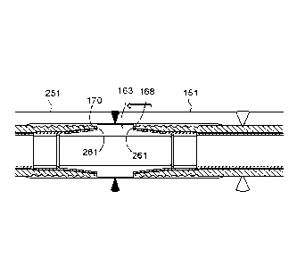
Excess liner is then trimmed back as shown in Figure 9 such that the liner 105
terminates short of the ends of the fitting 151, in alignment with an
insertion rim 161 (or
extending slightly beyond), in this case provided by the internal corrosion
resistant alloy
cladding 155. A fit-up sleeve 163 is then inserted into the end of the liner
105. The fit-
up sleeve 163 comprises a first liner engaging portion 165 which is tapered in
the
opposite sense to the taper of the second castellation section 157B. In this
region the
fit-up sleeve 163, and in particular the first liner engaging portion 165,
forces the liner
105 into the castellations in the second castellation section 157B and
provides a second
seal.
The fit-up sleeve 163 comprises a central portion 167 which is substantially
cylindrical
and has an outer diameter larger than that of the first liner engaging portion
165 so as to
define a shoulder 168 which abuts the insertion rim 161 of the fitting 151 and
creates an
airtight seal. Accordingly, the depth to which the fit-up sleeve 163 is
inserted can be
controlled or pre-determined. The fit-up sleeve 163 is symmetrical and
comprises a
second liner engaging portion 169, corresponding to the first liner engaging
portion 165,
at the opposite end of the fit-up sleeve 163.
Date Recue/Date Received 2022-03-07
CA 03153683 2022-03-07
- 26 -
It is foreseen that o-rings or gaskets can be employed at the interfaces
between, for
example, the shoulders and the insertion rims, to improve the seals at these
locations.
0-ring or gasket sizes can be selected from a look up table based on the final
dimensions and other parameters of the joint, for example gap sizes and/or the
actual
depth of the insertion rim following any necessary preparation of the fitting
for welding.
For example, "j" preparation for automatic welding or "v" preparation for
manual welding
will result in variability which can be compensated for using appropriately
sized o-rings
or gaskets.
Like the sealing ring 159, the fit-up sleeve 163 is formed from a corrosion
resistant alloy
but might likewise be formed from a different material such as carbon steel
suitable
corrosion protection.
It is envisaged that in some embodiments the sealing ring 159 could be
dispensed with
and the fit-up sleeve used alone. In such an arrangement, the first and second
liner
engaging portions of the fit-up sleeve might have the same axial extent as the
corresponding castellations. Likewise, the distal ends of the first and second
liner
engaging portions may comprise a first section of substantially constant outer
diameter
(at distal ends thereof) and a second section which tapers outwardly from the
first
section towards the central portion. The first section of substantially
constant outer
diameter would cooperate with the castellations of substantially constant
inner diameter,
and the tapered second section would cooperate with the tapered second
castellation
section.
To join the pipe 101, which we will now refer to as the first pipe, to a
second pipe 201,
the second pipe 201 is prepared in a similar manner to the first 101 up to but
before the
point at which the fit-up sleeve 163 is inserted. As such, the liner 205 of
the second pipe
201 is forced against a first castellation section 257A of a second fitting
251 by a sealing
ring 259, and the liner 205 terminates at a corresponding depth stop or
insertion rim 261.
As shown in Figure 11, the second pipe is stationary and the first pipe 101,
terminated
by the fitting 151 and fit-up sleeve 163, is pushed or otherwise moved towards
the
second pipe 201. The fit-up sleeve 163 is received in the second pipe 201 and
further
Date Recue/Date Received 2022-03-07
CA 03153683 2022-03-07
-27 -
movement causes the second liner engaging portion 169 to force the liner 205
into the
castellations in the second castellation section 257B. Note that the depth
stop or
insertion rim 161 of the first fitting 151 acts against the shoulder 168 of
the fit-up sleeve
163 as a ram to push the fit-up sleeve 163 into the liner 203. Similarly,
opposing
shoulder 170 abuts corresponding insertion rim 261 of the second fitting 251,
forming
another airtight seal.
In addition to providing seals (the implications of which are discussed below)
these
abutments also prevent the fit-up sleeve from being inserted beyond a target
depth (or
target depths). A further benefit of the fit-up sleeve 163 is that by having
an internal
diameter commensurate with the diameter of the bore 102 it can effectively act
as a
pigging sleeve which facilitates the transit of pigs over the resulting pipe
joint.
It will of course be understood that in this scenario the first pipe 101
(terminated by the
fitting 151 and fit-up sleeve 163) could be stationary and the second pipe 201
instead
pushed or otherwise moved towards the first pipe 101.
An annular girth weld can then be performed to join the fittings 151,251
together as
shown in Figure 12. Note that the airtight seals provided at the abutments
between
insertion rims 161,261 and shoulders 168,170 (respectively) prevent
backdraughts and
provide a boundary for a welding back purge, thus enabling CRA welding
(necessitated
by the use of a CRA cladding in the fittings 151,251) without the requirement
for purging
facilities within the closed pipeline. The relatively small volume of the
annular space in
the region of the weld (between the abutments) will be filled much more
quickly than in
normal back purged welding operations.
In an alternative embodiment, discussed briefly below with reference to Figure
13, the
fittings may be wholly formed from carbon steel rather than having CRA
cladding. In
such an embodiment this necessity for CRA welding and the associated
complications
(such as back purging) are not a concern. It is envisaged that the fittings
might be so
formed regardless of whether the pipeline is intended for transporting
corrosive species
because there may be no risk of said corrosive species reaching the fittings
because of
a barrier in the liner, the seals formed by the sealing rings and the fit-up
sleeve, and/or
Date Recue/Date Received 2022-03-07
CA 03153683 2022-03-07
- 28 -
the seals between the shoulders of the fit-up sleeve and corresponding
insertion rims.
As mentioned below, there may also be provided o-rings or gaskets to
supplement these
seals.
Figure 13 shows a joint between two lined pipes 1101 and 1201 created in a
similar
manner to that described above but with some key differences as shall now be
described. In this case, the fittings 1151,1251 are machined from solid
oversized carbon
steel pipe; that is, there is no internal CRA cladding. Instead, the
castellations
1157,1257 and the insertion rims 1161,1261 are formed directly in the carbon
steel pipe.
Of course, the fittings may be formed from any suitable material.
As intimated above, in this embodiment there are provided o-rings 1173 and
1273
between insertion rims 1161,1261 and shoulders 1168,1170 (respectively). Of
course,
the o-rings could be replaced or supplemented with gaskets or the like. 0-
rings or
gaskets may also (or alternatively) be provided between the sealing ring and
the fit-up
sleeve (as indicated by reference numerals 1175 and 1275) thus providing a
further seal.
Also, in this embodiment, the liners 1105,1205 comprise conventional
polyethylene pipe;
that is to say there is no barrier layer or porous inner layer. As such, the
pipeline
illustrated might be deemed unsuitable for, say, sour hydrocarbon service (for
which the
previous embodiment would be particularly suited) but might be particularly
well suited
for water injection flowlines.
Figure 14 shows an exploded view of a joint between two lined pipes 2101 and
2201,
similar to the joint shown in Figure 13 but again with some key differences as
shall now
be described. Again, the fittings 2151,2251 are machined from solid oversized
carbon
steel pipe. However, the castellations 2157,2257 are formed directly in the
carbon steel
pipe by creating a number of recesses.
In this embodiment there are provided o-rings 2173 and 2273 between insertion
rims
2161,2261 and shoulders 2168,2170 (respectively). However, rather than provide
o-
rings (or gaskets) between the sealing rings and the fit-up sleeve 2163, the
fit-up sleeve
Date Recue/Date Received 2022-03-07
CA 03153683 2022-03-07
-29 -
2163 is sized and shaped such that the leading ends of the fit-up sleeve 2163
touch the
respective sealing rings 2159,2259.
There is also provided a copper backing strip 2181 to accommodate automatic
welding
of the fittings 2151,2251. To this end, in this embodiment the ends of the
fittings are
also provided with j-shaped bevels 2183 to accommodate narrow gap welding.
In further contrast with the embodiment shown in Figure 13, the liners
2105,2205
comprise a barrier layer and porous inner layer, similar to the liner shown in
Figures 1 to
12. It is envisaged that the use of such liners will negate the need to use
CRA cladding
(the fittings in this embodiment comprised solely of carbon steel) even in the
presence of
very aggressive corrosive species, such as in sour hydrocarbon service. It
will however
be appreciated from the foregoing that the nature of the liner is irrelevant
to the
invention.
In other alternative embodiments, not shown, one or more of the welds can be
replaced
with alternative means of joining tubular components. For example, it is
foreseen that
instead of carrying out an annular girth weld between fittings, the fittings
could be
provided with flanges which are instead bolted or otherwise fastened together
(see
Figure 24 and brief discussion below). In such an arrangement, the action of
bringing
the flanges together by the tightening of bolts, application of a clamp (or
clamps), or the
like might remove the necessity to push the pipes (that is, the fittings on
the ends of the
pipes) together completely. In other words, the final stages of compressing
the liner
material between the fit-up sleeve and the castellations is achieved as the
flanges are
brought together. Also, instead of welding the fittings to the ends of the
respective
pipes, it is foreseen that the fittings could be attached to the ends of the
respective pipes
by flanged connections similar to that described briefly above. The fittings
could still be
welded together (when joining the pipes together) if required or desired.
.. As an alternative to flanged connections, and hence a further alternative
to welding,
other mechanical connections may be employed. For example, the inventive
arrangements described herein permit connections between lined pipe sections
using
Date Recue/Date Received 2022-03-07
CA 03153683 2022-03-07
- 30 -
mechanical connectors not previously deemed suitable for joining lined pipe
(certainly
not for hydrocarbon service, and especially not sour service).
Mechanical connectors such as GMC Limited's proprietary mechanical connector
which
forms part of their Intelligently Connected Pipe (ICPTM) product for offshore
riser and
flowline applications, and Oil States Industries' proprietary MerlinTM
connection, may be
employed to join the fittings together. In such an arrangement, according to a
further
alternative embodiment of the invention, one of the fittings comprises a pin
section and
the other fitting comprises a box section to receive the pin section of the
other. The box
section comprises a plurality of internal grooves and/or projections and the
pin section a
plurality of corresponding external grooves and/or projections.
When fitting together, the annular space between the pin section and the box
section is
pressurised (for example by injecting hydraulic fluid) so as to expand the box
section. A
clamp or a ram pushes (or pulls) the pin section fully into the box section,
the pressure is
reduced and the box shrinks onto the pin and the grooves and/or projections
cooperate
to provide a series of metal-to-metal seals. As with the flanged connection
described
above, the clamping action may provide the final stage of compression between
the fit-
up sleeve and the respective liner.
As discussed above, it is preferred that the pipes to be joined have been
lined using a
reduction and reversion process, such as Swagelining or roll-down, that
results in a
tight-fitting liner. It will also be understood that other methods of lining a
pipe with a liner
are possible, and this would include close-fit lining or fold and form lining
as described
briefly above.
The above described embodiments relate to what may be described as a "cut to
length"
operation in which an already-lined pipe is joined to another already-lined
pipe, and the
liner must be manipulated in order to retro-fit the fittings to the host
pipes. However, it is
foreseen that in many cases instead of attaching the fittings to the ends of
pipes that
have already been lined, the fittings may be attached to the ends of pipes
before the
pipes are lined, and the liner then pulled (or inserted) through both the pipe
and the
fitting and allowed to revert. In such situations, which might in fact
represent the most
Date Recue/Date Received 2022-03-07
CA 03153683 2022-03-07
- 31 -
common way in which the invention will be implemented and the benefits
realised,
Figure 7 may illustrate the final step of such a process in which the first
fitting 151 is
welded to the first host pipe 103 before inserting the first liner 105 (i.e.
the first pipe 101
is not initially a lined pipe), and the first liner 105 subsequently pulled
through the first
host pipe 103 and first fitting 151 (for example using a solid pulling head).
The second
pipe 201, to which the first pipe 101 is to be joined, may also have been
lined in this
way, that is after the second fitting 251 has been joined to the second host
pipe 203 (i.e.
the second pipe 201 is not initially a lined pipe either). All the following
steps (including
but not limited to inserting the sealing ring 159, trimming the liner 105 back
to the
insertion rim 161, inserting the fit-up sleeve 163 in the first pipe 101,
inserting the fit-up
sleeve in the second pipe 201 by pushing the first pipe 101 towards the second
pipe
201, and joining the first fitting 151 to the second fitting 251) may then be
carried out as
described above with reference to Figures 7 to 12.
It is likely that a joint between lined pipes formed using the latter method
(described in
the previous paragraph) may be indistinguishable from a joint between lined
pipes forms
using the "cut to length" method described above with reference to Figures 1
to 12.
Alternatively, the ends of the pipes themselves can be machined (or clad in
CRA
material and machined) to provide the desired internal profile (in which case
any
features described above in relation to fittings may be provided instead in
the pipe; for
example castellations, flanges or mechanical connections). Accordingly, it is
possible to
also omit the steps set out above and discussed with reference to Figures 7
(at least),
and corresponding steps as they may relate to other embodiments described
herein.
Furthermore, the subsequent steps of inserting the sealing ring (Figure 8) and
cutting
back the liner to the depth stop or insertion rim (Figure 9) could constitute
the final steps
of a lining process which produces a section of lined pipe ready to be joined,
as
required, to another like section of lined pipe by inserting a first end of a
fit-up sleeve into
one of the lined pipes, pushing a second end of the fit-up sleeve into the
other lined pipe,
and then joining the two lined pipes (or their respective fittings) together
by welding or by
a mechanical connection therebetween as intimated above.
Date Recue/Date Received 2022-03-07
CA 03153683 2022-03-07
- 32 -
As described above in relation to Figure 8, the sealing ring is inserted into
the fitting
within the liner so as to prevent subsequent movement of the liner (should it
be required)
and to provide a seal which prevents axial transit or permeation of liquid or
gas along the
porous layer in the region between the sealing ring and the respective
fitting. The seal is
formed by compressing all layers of the liner, and in particular the porous
layer which is
compressed sufficiently to render it non-porous. Another seal is provided by
the fit-up
sleeve which also compresses a subsequent portion of the liner against the
fitting and a
further seal may be provided by the optional provision of o-rings or gaskets
between the
fit-up sleeve and the sealing ring (as illustrated in Figure 13).
In the unlikely event that the porous layer is not sufficiently compressed,
for example
because the sealing ring is incorrectly sized or incorrectly inserted, there
is a slight
possibility that liquid or gas may be able to transit or permeate through the
porous layer
in this region and therefore bypass the sealing ring when in service. It is
expected that
even in this situation, said liquid or gas would follow the path of least
resistance and
transit through the uncompressed porous layer at the other side of the sealing
ring and
re-enter the internal bore of the lined pipe. Nonetheless, it is seen as
desirable to
mitigate risk and to this end the process described above with reference to
Figures 1 to
12 (or 7 to 12 as the case may be) may be modified as follows.
Figure 15 corresponds to Figure 9 and this embodiment may share any or all
features
and steps leading up to this point with that embodiment (for example as
described with
reference to Figures 1 to 8). Figure 15 (similarly to Figure 9) shows that
after insertion of
the sealing ring 3159, the liner 3105 is trimmed back such that it terminates
short of the
ends of the fitting 3151, coincident with (or slightly proud of) an insertion
rim 3161
formed by the castellated internal corrosion resistant alloy cladding 3155.
A section of the porous layer 3105A is then removed such that the porous layer
3105A
terminates at the edge or end of the sealing ring 3159 as shown in Figure 16.
The exact
.. process by which the porous layer 3105A is removed will be dependent on the
materials
from which the liner 3105 is made (for example the material of the porous
layer and/or
the adhesive between the porous layer and the barrier layer 3111). One way in
which
the porous layer 3105A may be removed is by chemically dissolving the polymer
Date Recue/Date Received 2022-03-07
CA 03153683 2022-03-07
- 33 -
material of the porous layer 3105A without damaging the barrier layer 3111.
Alternatively, the porous layer 3105A may be mechanically removed, for example
by
cutting or by machining to reduce the thickness of the porous layer 3105A and
subsequently peeling it away from the barrier layer 3111. The effectiveness of
the
adhesive between the porous layer 3105A and the barrier layer 3111 can be
reduced,
aiding removal of the porous layer 3105A, for example by application of heat
or chemical
means (such as a suitable acid composition). Alternatively, the adhesive (at
least in this
region) can be selected to enable the porous layer to be peeled away from the
barrier
layer.
Subsequent steps may then correspond to the abovementioned embodiment (for
example as described with reference to Figures 10 to 12). As shown in Figure
17
(similarly to Figure 10) a fit-up sleeve 3163 is then inserted into the end of
the liner 3105.
The fit-up sleeve 163 comprises a first liner engaging portion 3165 which is
tapered in
the opposite sense to the taper of the second castellation section 3157B and
the liner
3105 is compressed therebetween. In contrast with the abovementioned
embodiment,
the fit-up sleeve 3163, and in particular the first liner engaging portion
3165, is in direct
contact with the now-exposed barrier layer 3111. The absence of the porous
layer in
this region means that any liquid or gas which transits or permeates past the
sealing ring
3159 through the compressed porous layer vents directly back to the internal
bore.
As shown in Figure 18 (similarly to Figure 11), to join the first pipe 3101 to
a second pipe
3201, the second pipe 3201 is prepared in a similar manner to the first 3101
up to but
before the point at which the fit-up sleeve 3163 is inserted, including
removing the
porous layer 3205A up to the sealing ring 3259. The first pipe 3101,
terminated by the
fitting 3151 and fit-up sleeve 3163, is pushed or otherwise moved towards the
second
pipe 3201. The fit-up sleeve 3163 is received in the second pipe 3201 and
further
movement causes the liner 3205 to be compressed between second liner engaging
portion 3169 and the second castellation section 3257B. Again, in contrast
with the
abovementioned embodiment, the fit-up sleeve 3163, and in particular the
second liner
engaging portion 3169, is in direct contact with the now-exposed barrier layer
3211. The
absence of the porous layer in this region means that any liquid or gas which
transits or
permeates past the sealing ring 3259 also vents directly back to the internal
bore.
Date Recue/Date Received 2022-03-07
CA 03153683 2022-03-07
- 34 -
An annular girth weld can then be performed to join the fittings 3151,3251
together, for
example as described above with reference to Figure 12.
In a variation of the process described above, instead of terminating the
porous layer
3105A at the edge of the sealing ring 3159, the porous layer 3105A may be
terminated
between the ends of the sealing ring such that the interface or termination
resides
behind the sealing ring 3159 (or between the sealing ring 3159 and the fitting
3151). In
this way, the transition between the porous layer 3105A and the barrier layer
3111 may
be sealed. This might be achieved by removing a suitable length of the porous
layer
3105A prior to insertion of the sealing ring 3159, the sealing ring 3169
effectively
extending between a portion of the liner 3105 where there is a porous layer
3105A
present and where the barrier layer 3111 is exposed. Alternatively, in another
variation
of the process described above, the porous layer 3105A may be terminated at a
location
between the insertion rim 3161 and the sealing ring 3159 such that it resides
behind the
fit-up sleeve 3163 (or between the first liner engaging portion 3165 of the
fit up sleeve
3163 and the fitting 3151).
An additional benefit of the invention, which overcomes significant
disadvantages of prior
art methods of joining lined pipe, is also realised when it is necessary to
repair, or
specifically re-make, the weld between the fittings. Conventionally, non-
destructive
testing is carried out on a weld to make sure it is acceptable for service. If
it is not
acceptable, but it can be repaired, then a repair is carried out and non-
destructive testing
carried out to make sure the repaired weld is acceptable for service. If the
original or the
repaired weld cannot be repaired, it is necessary to re-make the weld.
Remaking welds
with all existing weldable connectors is time consuming on the critical path
and thereby
significantly expensive and contains reasonable operational technical risk.
The present
invention negates the risk and the time taken to effect the re-weld and
thereby
significantly reduces the cost.
To re-make a welded pipe joint the pipe joint may be cut through, the first
and second
fittings pulled apart and the fit-up sleeve removed. The skilled person will
understand
that in order to re-make the weld, it would be usual to cut out a section of
the joint
Date Recue/Date Received 2022-03-07
CA 03153683 2022-03-07
- 35 -
containing the weld. This might, for example, be a 30 mm section. In this case
it would
not be possible to use the same fit up sleeve when re-making the joint because
the ends
of the fittings would not meet; accordingly a shorter fit up sleeve (for
example, 30 mm
shorter), would be required to ensure proper fit up is maintained when the
fittings are
brought together and welded.
If cutting through the pipe joint also cuts through the fit-up sleeve, the
resulting portions
of the fit-up sleeve can be removed separately from the first and second
fittings. But in
general, only the fittings will be cut and the fit-up sleeve can be removed
whole. It is
foreseen that this fit-up sleeve could be re-used in another joint.
Figures 19 to 23 illustrate a further alternative embodiment which
incorporates a number
of features specifically intended to facilitate repairing or re-making welds
between the
first and second fittings of the invention. Fit-up sleeves of various
embodiments
described above comprise a substantially cylindrical central portion of an
outer diameter
larger than that of the substantially conical liner engaging portions at
either end thereof,
providing shoulders which abut corresponding insertion rims of the fittings
into which
they are inserted. As intimated above, in this way the depth to which the fit-
up sleeve is
inserted can be controlled or pre-determined.
In the embodiment illustrated in Figures 19 to 23 there are provided a number
(three in
this example) of spacer rings 4501A,4501B,4501C which are configured to be
inserted
between the shoulders of the fit-up sleeve 4163 and the insertion rims
4161,4261 of the
fittings 4151,4251 (or pipes as the case may be), to further control and
indeed modify
the depth to which the fit-up sleeve 4163 is inserted. Figure 19 corresponds
to Figures
11 and 18 of embodiments described above and (a) shows a connector assembly
ready
for welding to create a joint between respective lined pipes. Located between
the
shoulders of the fit-up sleeve 4163 and the insertion rims 4161,4261 are a
pair of spacer
rings 4501A of a first length A.
If the resulting weld fails or otherwise needs to be repaired or re-made, the
weld is cut
out and the fit-up sleeve 4163 and the spacer rings 4501A are removed. After
re-
bevelling the ends of the fittings 4151,4251 (or pipes as the case may be), a
pair of
Date Recue/Date Received 2022-03-07
CA 03153683 2022-03-07
- 36 -
spacer rings 4501B of a second, shorter, length B are inserted and the fit-up
sleeve
4163 re-inserted (b). The difference in length of spacer rings 4501B with
respect to
spacer rings 4501A corresponds to the size of the weld cut-out such that the
ends of the
fit-up sleeve 4163 extend to the same position relative to the castellation
regions
4157,4257 (discussed further below). Should the resulting repair or re-made
weld also
need to be repaired or re-made the same process is followed but in this case a
pair of
spacer rings 4501C of a third, shorter again, length C are inserted and the
fit-up sleeve
4163 re-inserted. Again, the difference in length of spacer rings 4501C with
respect to
spacer rings 4501B corresponds to the size of the weld cut-out such that the
ends of the
fit-up sleeve extend to the same position relative to the castellation regions
4157,4257.
Throughout the process of repairing or re-making welds, however many times
this is
performed (within reason), the sealing rings 4159,4259 hold the liners
4105,4205 in
place. In this example the number of weld attempts is limited to three but
there is no
limit on the number of attempts which can be accommodated provided a
sufficient
number of spacer rings are provided (and the fit-up sleeve is suitably
dimensioned).
In this embodiment, the castellation regions 4157,4257 can be seen to comprise
two
distinct sets of axially separated castellations 4157A,4257A and 4157B,4257B
(see
Figure 20 in particular). The first set of castellations 4157A,4257A
correspond to the
sealing rings 4159,4259 that hold the liners 4105,4205 in place, and the
second set of
castellations 4157B,4257B correspond to the liner engaging portions 4165,4169.
As will
be apparent by comparing the relative insertion depths of the fit-up sleeve
4163 in each
of Figures 19 (a), (b) and (c) this separation serves to define distinct
sealing regions. Of
course, it is foreseen that the castellation regions might comprise a single
continuous
castellation, which may comprise a continuous taper, rather than distinct sets
which may
be of different tapers or one tapered and one of a constant inner diameter.
Figure 24 illustrates a variant of the above-described embodiment (although
the variation
is applicable to any embodiment) in which instead of carrying out an annular
girth weld
(or other kind of weld) between the fittings (or pipes as the case may be),
the fittings (or
pipes) are provided with flanges 5199,5299 which are instead bolted together.
Steps
leading up to this point may be the same or similar to those steps leading up
to (but not
Date Recue/Date Received 2022-03-07
CA 03153683 2022-03-07
- 37 -
including) the final step of welding fittings (or pipes as the case may be)
together,
although it is envisaged that the flanges may aid in the physical insertion of
the sealing
ring and the fit-up sleeve in the first fitting. Other means of fastening the
flanges
5199,5299 together may of course be provided. As intimated above, in such an
arrangement the action of bringing the flanges 5199,5299 together by the
tightening of
bolts, application of a clamp (or clamps), or the like may constitute the
final stages of
compressing the liners 5105,5205 between the fit-up sleeve 5163 and the
respective
castellations 5157,5257, although it is envisaged that the sealing rings and
the fit-up
sleeve (or just the fit-up sleeve as the case may be) may deliver the seal
alone. This
makes the design and the fitting of the flanges much less sensitive in terms
of leaks.
Furthermore, as suggested above, spacer rings 5501A may actually be dispensed
with
as it is possible to match the fit-up sleeve to the flange, and in the event
the flange has
to be opened after fitting for any reason, there will be no requirement for a
metal cut out
(as in a re-weld) as the flanges are mechanically joined. In general however
it may be
preferred to retain the sealing rings, for example to prevent liner movement,
although in
some embodiments these may also be dispensed with (for example if by design
there is
an extremely tight fit between the liner and the pipe and/or fitting such that
the liner will
not move).
The invention provides methods and apparatus for making lined pipelines. Pipes
are
joined together by attaching fittings at their ends and joining the fittings
together. Within
the joint there is a fit-up sleeve which forces liners against respective
fittings and
provides corresponding seals. Other seals can be provided by inserting sealing
rings
which force different portions of the liners against different portions of the
fittings. The
fit-up sleeve and sealing rings may force the liners against castellations
which prevent
movement of the liners. The fit-up sleeve may cooperate with insertion rims on
the
fittings to provide very accurate spacing, or touching edges which can be
desirable if
automatic welding is employed. The seals provided by the fit-up sleeve also
eliminate
backdraughts and assist welding operations. Furthermore, the fit-up sleeve
permits
pigging through the pipe joint and therefore along the length of the resulting
lined
pipeline. It is foreseen that the need for CRA components and CRA welding can
be
largely if not wholly dispensed with.
Date Recue/Date Received 2022-03-07
CA 03153683 2022-03-07
- 38 -
In hydrotests carried out to evaluate the integrity of pipe joints formed in
accordance with
the invention, witnessed by Lloyd's Register, a test spool was pressure cycled
between
zero and 345 bar three times over the course of a week. During this time no
fluid
passed the fit up sleeve and the carbon steel surface of the host pipe was
untouched by
the test water. The invention is therefore already proven capable of use in
water
injection service without requiring the use of corrosion resistant alloys, and
the Applicant
expects that further testing will similarly confirm capability for use in
hydrocarbon service
and, in particular, sour hydrocarbon service.
The above embodiments and any suggested variants are described in context.
However, it will be readily understood that each of the embodiments is capable
of being
combined (in whole or in part) with one or more of the other embodiments
(again, in
whole or in part). For example, it is foreseen that a joint may be formed in
which a first
pipe is provided with a fitting comprising a CRA cladding and a second pipe
(to which
the first will be joined) may be provided with a fitting which does not
comprise a CRA
cladding. As a further example, the castellations formed directly in the pipe
in one or
more embodiments might be replaced with grooves as in one or more other
embodiments. As a yet further example, where barrier pipe or the Applicant's
improved
pipe liner is employed, portions of the innermost or porous layer may be
removed in
variants of those embodiments which do not expressly describe this step.
As may be used herein, the terms bottom, lower, below and the like are
descriptive of a
feature that is located towards a first end/side of an apparatus, system or
component
while the terms top, upper, above and the like are descriptive of a feature
that is located
towards a second, opposing end/side of the apparatus, system or component.
Such an
apparatus, system or component may be inverted without altering the scope of
protection which, as below, is defined by the appended claims. Likewise, terms
which
are descriptive of movement or direction, such as towards or apart, shall be
understood
in the broadest sense as referring to relative movement or direction.
Throughout the specification, unless the context demands otherwise, the terms
"comprise" or "include", or variations such as "comprises" or "comprising",
"includes" or
Date Recue/Date Received 2022-03-07
CA 03153683 2022-03-07
- 39 -
"including" will be understood to imply the inclusion of a stated integer or
group of
integers, but not the exclusion of any other integer or group of integers.
The foregoing description of the invention has been presented for the purposes
of
illustration and description and is not intended to be exhaustive or to limit
the invention to
the precise form disclosed. The described embodiments were chosen and
described in
order to best explain the principles of the invention and its practical
application to
thereby enable others skilled in the art to best utilise the invention in
various
embodiments and with various modifications as are suited to the particular use
contemplated. Therefore, further modifications or improvements may be
incorporated
without departing from the scope of the invention as defined in the summary of
invention
and by the appended claims. For example, and for the avoidance of doubt, the
methods
and apparatus described herein are not limited to use with pipe liners
comprising a
barrier layer and/or a porous inner pipe but are also applicable to
conventionally lined
pipe. Furthermore, it is foreseen that fittings and/or pipes may be joined by
mechanical
connections such as flanges rather than welding.
Date Recue/Date Received 2022-03-07