Note: Descriptions are shown in the official language in which they were submitted.
Mauser-Werke GmbH -1 - P01/19 PCT
Transverse cross-member spring element 16.10.2020
Pallet container
The present invention relates to a pallet container for storing and
transporting fluid or
flowable filling materials, having a thin-walled, rigid inner container made
from
thermoplastic plastics material, having a tubular grid frame which tightly
surrounds the
plastics inner container as a supporting covering and which comprises
horizontal and
vertical tubular rods which are welded to each other, and having a base pallet
on which the
plastics inner container is positioned and to which the tubular grid frame is
securely
connected, wherein two rod-shaped transverse cross-members are provided above
the
plastics inner container and are fixed with the two ends thereof to two
mutually opposite
side walls in the upper region of the tubular grid frame. The rod-like
transverse cross-
members are intended to prevent excessive bulging of the plastics inner
container or the
upper base thereof with a central screw cap, in particular in the event of
transport impacts
and dynamic vibrations, and also serve inter alia, in the event of an
undesirable
overturning of the pallet container, to retain the plastics inner container in
the tubular grid
frame on the base pallet and to prevent it from sliding out of the tubular
grid frame. In order
to allow a simple exchange of the plastics inner container for multiple uses
of the pallet
container, the transverse cross-members are releasably secured with the two
ends thereof
in the upper region of the tubular grid frame, generally screwed. Such a
pallet container
having two transverse cross-members extending parallel is known, for example,
from the
publication WO 2012085940 A2. In a pallet container which is described in the
publication
DE 4425630 Al, exactly four transverse cross-members are provided, wherein two
transverse cross-members which obliquely intersect with each other cover one
half of the
plastics inner container, respectively.
Problem:
When pallet containers are intended to be used for storing and transporting
hazardous
liquid filling materials, such as, for example, aggressive chemicals, these
pallet containers
then require a so-called hazardous goods approval of an official national
inspection body,
in Germany this is the BAM (Federal Institute for Materials Research and
Testing). In order
to obtain such a hazardous goods approval, the various types of pallet
containers are
subjected to a specific construction type testing with various loading states,
such as, for
example, an internal pressure test, drop test and vibration test. During the
vibration test,
Date Recue/Date Received 2022-04-06
- 2 -
significant transport loads (impacts, shocks) are simulated on a filled pallet
container. In
this instance, the liquid column in the plastics inner container can be
subjected to
significant dynamic vibrations. These vibrations cause powerful alternating
loads on the
side walls of the plastics inner container and are transmitted directly to the
tubular grid
frame which tightly surrounds the plastics inner container as a supporting
covering. Since
a pallet container generally has two longer and two shorter side walls, the
two longer
opposing side walls are generally subjected to higher loads and are therefore
stabilized by
the engaging transverse cross-members. The upper base of the plastics inner
container
also carries out significant dynamic upward and downward vibrations which act
on the
transverse cross-members. In the event of a bulging of the upper base in an
upward
direction, the known straight transverse cross-members which extend parallel
with each
other are pressed upward and significant tensile loads act on the two fixing
locations of the
transverse cross-members on the tubular grid frame between the mutually
opposing side
walls of the tubular grid frame, whereby the upper region of the tubular grid
frame is pulled
inward. When the upper base is lowered, the opposing side walls of the
plastics inner
container and of the tubular grid frame bulge outward, wherein the upper
region of the
tubular grid frame is also pressed outward. In this instance, the transverse
cross-members
with the two fixing locations thereof are again subjected to a significant
tensile loading.
This alternating loading is repeated at high frequency over a relatively long
period of time
and has a wearing effect on the corresponding components of a pallet
container.
Problem:
An objective of the present invention is to reduce these disadvantageous
tensile stresses
and to absorb the effect of tensile loads on the fixing locations of the
transverse cross-
members and accordingly on the upper region of the tubular grid frame and to
mitigate
tension peaks.
Solution:
The intended reduction of disadvantageous tensile stresses is achieved in that
the two
rod-like transverse cross-members are constructed as resilient spring
elements. As a
result of the resilient construction of the two transverse cross-members as
spring
elements, the rigid connection of previously conventional transverse cross-
members which
extend in a linear straight manner to the opposing side walls of the tubular
grid frame is
eliminated and a limited resilience is "incorporated" into the upper plane of
the tubular grid
Date Recue/Date Received 2022-04-06
- 3 -
frame. In the event of a bulging of the upper base in an upward direction, the
tensile forces
which occur on the two fixing locations of the transverse cross-members are
reduced and
the upper region of the tubular grid frame is pulled inward to a lesser
extent. In the event of
a lateral bulging of the plastics inner container and the connected bulging of
the opposing
side walls of the tubular grid frame in an outward direction, the tensile
forces which occur
in the upper region of the tubular grid frame are significantly reduced as a
result of the
transverse cross-members which are constructed as resilient spring elements
and the
operational safety of filled pallet containers in the event of dynamic
transport loads is
significantly increased.
According to the present invention, there is provision for the transverse
cross-members
which are constructed as resilient spring elements not to be formed so as to
extend in a
linear manner, but instead to have one or more curved portions. In this
instance, the actual
length of the transverse cross-members between the two fixing locations
thereof is
constructed to be greater than the direct spacing of the two fixing locations
at the ends of
the transverse cross-members in the upper region of the tubular grid frame. As
a result of
this structural configuration, the transverse cross-members are, on the one
hand, in the
event of tensile loading, when the tubular grid frame bulges outward, flexible
in the
horizontal longitudinal direction thereof, on the other hand, even in the
event of lateral
pressure loading - as a result of a bulging of the upper base of the plastics
inner container
in an upward direction - they are configured to be flexible in a vertical
direction.
This is achieved in an embodiment of the invention by the transverse cross-
members
being constructed between the two fixing locations thereof so as not to extend
in a linear
manner, but instead in a curved manner, and to have a comparatively large
curve.
The construction of the two transverse cross-members as resilient spring
elements is in a
preferred embodiment achieved as a result of an arcuately curved form having a
large
shaped curve. In this instance, the transverse cross-members - when viewed in
the fitted
state ¨ are bent in the horizontal plane, wherein the curves each have a
comparatively
large radius and are directed outward in the direction of the two opposing
shorter side
walls of the tubular grid frame. In the fitted state, the arcuately curved
transverse cross-
members are consequently positioned fiat on the upper base of the plastics
inner
Date Recue/Date Received 2022-04-06
- 4 -
container, wherein the curves of the two transverse cross-members are
orientated so as to
be directed away from each other.
Advantageously, the two transverse cross-members are guided by means of a
retention
apparatus which is formed from the upper base of the plastics inner container
in the form
of a closed retaining lug. In modified form, the retention apparatuses which
are formed
from the upper base of the plastics inner container may also be constructed as
carrier pins
which are open at one side. These carrier pins which are open at one side are
also
referred to below as hook lugs.
The closed retaining lugs or the carrier pins which are open at one side are
arranged
laterally beside the central filling opening of the plastics inner container
which can be
closed by means of a screw cap, and the center of the curve of the two
transverse cross-
members is located precisely below a retaining lug or below a carrier pin. The
transverse
cross-members with their arcuately curved shape can, on the one hand, in the
event of a
bulging of the upper base in an upward direction and in a downward direction -
for
example, also in the event of an internal pressure test or drop test - give
way resiliently in
a vertical direction and adapt to the bulge, they virtually "follow" the shape
of the upper
base.
In another embodiment of the invention, the transverse cross-members in the
form of
resilient spring elements may also be provided with two or three smaller
curves with
smaller radii in comparative terms.
The fixing locations of the arcuately curved transverse cross-members are ¨ in
comparison
with previously conventional straight transverse cross-members ¨ displaced
further to the
center of the upper region of the tubular grid frame, at locations where the
largest bulges
with the largest tensile loads occur and are intended to be absorbed.
During the vibration test, the arcuately curved transverse cross-member acts
as a resilient
spring. During the vibration, the upper base of the inner container vibrates
up and down.
These vibrations bring about in the upper and lower end points a resilient
bending of the
previously conventionally linear transverse cross-members upward and downward
which is
converted directly into a reduction of the spacing between the fixing
locations. As a result
Date Recue/Date Received 2022-04-06
- 5 -
of this reduction of the spacing, the tubular grid frame in the upper region
is drawn inward
significantly with each travel. With the new "spring solution" which is also
flexible in a
longitudinal direction, however, at the upper edge of the tubular grid frame a
substantially
reduced deformation and therefore a reduced loading on the pallet container
are achieved.
In order to obtain optimum resilience and spring-like action of the transverse
cross-
members, there is provision for the length of the transverse cross-members to
be
constructed according to the line of curvature thereof between the two fixing
locations
thereof between 1% and 5% greater than the direct spacing (corresponding to a
chord)
between the two fixing locations. The size of the curve and the arcuately
curved form of
the transverse cross-members is thereby brought about as a resilient spring
element.
In a preferred embodiment of the invention, there is provision for the two
ends of the
transverse cross-members to be powerfully compressed in the radial direction,
for a
corresponding internal thread, for example, M8, to be directly formed in the
compressed
portions and for the two ends of the transverse cross-members to be securely
screwed on
the front side to an upper horizontal or vertical tubular rod of the tubular
grid frame. For
this construction variant, there is provision for the two ends of the
transverse cross-
members each to be screwed at the end to the upper end of two adjacent
vertical tubular
rods.
In another embodiment of the invention, there is provision for a threaded nut
having an
internal thread to be inserted in a secure manner at the end face in both ends
of the
transverse cross-members and for the transverse cross-members to be screwed in
a
secure manner on the end face ¨ so to speak, in the axial direction - to an
upper horizontal
or vertical tubular rod of the tubular grid frame. In this instance, the
threaded nut which is
inserted in a secure and non-releasable manner into the transverse cross-
member which
is constructed as a hollow tubular profile can be simply pressed in,
compressed or welded.
The invention is explained and described in greater detail below with
reference to
embodiments which are illustrated in the drawings, in which:
Figure 1 is a perspective view of a pallet container according to the
invention,
Date Recue/Date Received 2022-04-06
- 6 -
Figure 2 is an enlarged partial view of the upper region of the pallet
container according
to the invention according to Figure 1,
Figure 3 is a plan view of a transverse cross-member which is in the form of a
resilient
element,
Figure 4 is a side view of another embodiment of a transverse cross-member,
Figure 5 is an enlarged partial view of the left end region of the
transverse cross-
member according to Figure 4,
Figure 6 is an enlarged partial view with a transverse cross-member being
connected to
the upper region of a tubular grid frame,
Figure 7 is an enlarged partial view of the right end region of a
transverse cross-
member with a threaded nut inserted,
Figure 8 is an enlarged partial cross sectional view with an end-side screw
connection
of a transverse cross-member to the upper region of the tubular grid frame,
Figure 9 is a partial view of a hook lug (carrier pin) which is formed
from the upper base
of the plastics inner container and which engages over a transverse cross-
member and
Figure 10 is an enlarged partial cross sectional view with a conventional
connection of a
transverse cross-member to the upper region of the tubular grid frame.
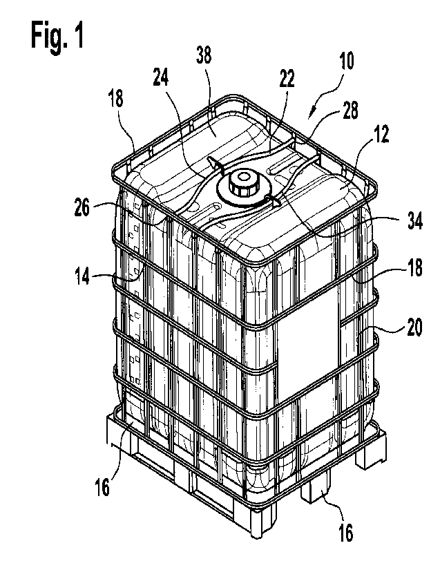
Figure 1 illustrates a pallet container 10 according to the invention (also
referred to as an
"IBC" = Intermediate Bulk Container) for storing and transporting fluid or
flowable filling
materials. The pallet container 10 comprises a thin-walled, rigid plastics
inner container 12
made from thermoplastic plastics material, a tubular grid frame 14 which
tightly surrounds
the plastics inner container 12 as a supporting covering and which comprises
horizontal
and vertical tubular rods 18, 20 which are welded to each other and a base
pallet 16 on
which the plastics inner container 12 is positioned and to which the tubular
grid frame 14 is
Date Recue/Date Received 2022-04-06
- 7 -
securely connected. Two rod-shaped transverse cross-members 22 are provided
above
the plastics inner container 12 and are fixed with the two ends thereof to two
mutually
opposite side walls of the upper tubular grid frame 14. In this case, the two
transverse
cross-members 22 are in the form of resilient spring elements 24 in an
arcuately curved
form. The particular constructive embodiment of the transverse cross-members
22 is
distinguished in that they are constructed not to be rectilinear or linear
between the two
fixing locations 26, 28 thereof, but instead in a curved manner and have a
comparatively
large curve 34. In this case, the length of the transverse cross-members 22
between the
two fixing locations 26, 28 thereof is constructed in a completely unusual
manner to be
greater than the direct spacing of the two fixing locations 26, 28 at the ends
of the
transverse cross-members 22. In the present embodiment, the fixing locations
26, 28 are
arranged at the ends of the transverse cross-members 22 in each case on two
vertical
rods closely below the uppermost horizontally extending tubular rod 18 between
two
opposing side walls of the tubular grid frame 14.
Specifically, the length of the transverse cross-members 22 between the two
fixing
locations 26, 28 thereof is constructed to be between 1% and 5%, preferably 3%
greater
than the direct spacing between the two fixing locations 26, 28. For standard
pallet
containers having a filling volume of 600, 1000 or 1200 liters and which have
the same
dimension in terms of width and length, the spacing of the two fixing
locations 26, 28 from
each other is approximately 960 mm and the effective length of the transverse
cross-
members 22 is approximately 993 mm. For the same standard pallet containers,
the
curved transverse cross-members 22 are intended to have a large radius of
curvature
between 300 mm and 700 mm, preferably 500 mm.
The above-described constructive embodiment of the invention can be better
seen in
Figure 2 in an enlarged cut-out. In this case, it is shown that the arcuately
curved
transverse cross-members 22¨ in the fitted state ¨ are positioned flat in a
horizontal plane
on the upper base 38 of the plastics inner container 12, wherein the large
curves 34 of the
two transverse cross-members 22 are orientated so as to be directed away from
each
other.
Date Recue/Date Received 2022-04-06
- 8 -
In a modified embodiment, there may be provision for the transverse cross-
members 22 to
be constructed as resilient spring elements with two or three smaller curves
which are
orientated in a horizontal plane and which have smaller radii in comparison.
In any case, the arcuately curved transverse cross-members 22 - in the
installed state -
are each guided through a retaining lug 40 which is formed from the upper base
38 of the
plastics inner container 12, wherein the retaining lugs 40 are arranged in an
engaging
manner at the center of the fitted curved transverse cross-members 22 (another
form of
the retaining lugs is illustrated in Figure 9).
Figure 3 is a plan view of a curved transverse cross-member 22 which is in the
form of a
spring element and which has a large radius of curvature of approximately 500
mm. The
transverse cross-members may be constructed as a hollow tube having a round or
square
cross section. In a preferred embodiment, the transverse cross-members 22, 42
have a
round tubular profile with a diameter between 16 mm and 24 mm, preferably 20
mm, and a
wall thickness between 0.8 mm and 1.2 mm, preferably 0.9 mm. According to
another
construction type, however, the transverse cross-members 22, 42 may also have
a square
tubular profile with a side length between 14 mm and 20 mm, preferably 16 mm,
and a wall
thickness between 0.8 mm and 1.2 mm, preferably 0.9 mm.
Figure 4 is a side view of another embodiment of a transverse cross-member
with two
curves 42 which have in the end regions thereof ¨ when viewed in the fitted
state ¨ a
downwardly formed small curve 36 with a comparatively small radius and
upwardly
directed ends and (as can be seen in detail in Figure 8) are each screwed on
the front side
from below against the uppermost circumferential horizontal tubular rod 18.
One end of the
transverse cross-member with two curves 42 with downwardly formed small curves
36 with
a small radius is illustrated as an enlarged partial view in Figure 5. A
threaded nut 30 with
an internal thread 44 (for example, M8 or M10) is securely inserted in the
open ends of the
hollow tubular profile of the transverse cross-member with two curves 42 (see
also Figure
7). The non-releasably inserted threaded nut 30 can simply be pressed in,
compressed or
welded.
One possible fixing method, in which a threaded screw 48 is screwed at the end
into the
end of the hollow tubular profile of the transverse cross-member 22 can be
seen in Figure
Date Recue/Date Received 2022-04-06
-9-
6. In this case, the transverse cross-member 22 is fixed close below the
uppermost
horizontal tubular rod 18 by means of the threaded screw 48 which is screwed
from the
exterior at the end ¨ in the horizontal direction ¨ to the upper flattened
ends of two
mutually opposite vertical tubular rods 20.
Figure 7 correspondingly shows the open end of the hollow tubular profile of
the
transverse cross-member 22 (having only one large curve) with a securely
inserted screw
nut 30 having an internal thread 44. The transverse cross-member with 2 curves
42 is, as
described above, screwed at the end from below against the uppermost
circumferential
horizontal tubular rod 18 of the tubular grid frame in a secure but re-
releasable manner.
Another possible fixing method with the transverse cross-member being screwed
at the
end and with two curves 42 is shown in Figure 8 as an enlarged illustration.
In this case,
the two ends of the transverse cross-members with 2 curves 42 are compressed
powerfully in the radial direction, wherein a corresponding internal thread 46
is formed
directly in the compressed portions 32. In this case, the transverse cross-
members with 2
curves 42 with the smaller curves at the end regions thereof are fixed at the
end from
below against the uppermost horizontal tubular rod 18 by means of a threaded
screw 48
which is screwed in from above ¨ in the vertical direction. Advantageously,
the uppermost
horizontal tubular rod 18 is slightly recessed at the top at the bore hole and
the threaded
screw 48 is configured as a flat-head, countersunk head or raised countersunk
screw so
that it does not project upwardly. The compressed portions 32 with a
correspondingly
formed internal thread 46 can naturally also be produced in the case of the
transverse
cross-member 22 (with only one large curve). The end-side screw connections
further
have the advantage that the screw tip is located completely in the hollow
tubular profile of
the transverse cross-members 22, 42 and is covered so that injuries can no
longer thereby
result, as was often the case with previously conventional open screw
connections with a
projecting screw tip.
Previously conventional linear cross-members can be screwed directly in the
center axis
with screws at the end only with difficulty. When the screws are tightened,
the cross-
member also rotates and it has to be fixed for assembly. This fixing is
dispensed with in
the case of the arcuately curved shape of the transverse cross-members.
Date Recue/Date Received 2022-04-06
- 10 -
As previously mentioned, the arcuately curved transverse cross-members 22¨ in
the fitted
state ¨ are each guided through a retaining lug 40 which is formed from the
upper base 38
of the plastics inner container 12. The retaining lugs 40 may in another
embodiment also
be constructed as carrier pins 50 (also referred to as hook lugs) which are
open at one
side, as shown in Figure 9. In this instance, the curved transverse cross-
members 22 are
engaged over and fixed centrally from the outer side to the inner side by
carrier pins 50
which are constructed in a solid manner by means of material thickening.
The differently configured versions of the transverse cross-members 22, 42
enable a
different configuration of the securing of the two ends of the transverse
cross-members 22,
42 to the upper tubular grid frame 14. In addition to the end fixings
described, the ends 52
of the transverse cross-members 22, 42¨ in a manner known per se ¨ may also be
flattened, placed flat around the uppermost horizontal rod of the tubular grid
frame 14 and
screwed by means of a threaded screw 54 below the uppermost tubular rods 18,
as can
be seen in Figure 10.
In a combined form, the transverse cross-members 22, 42 may be constructed as
resilient
spring elements also with two smaller curves which are orientated in a
vertical plane with
smaller radii in comparison and one, two or three smaller curves which are
orientated in a
horizontal plane with smaller radii in comparison. Such a formation may be
advantageous
for a torque-neutral construction. The embodiments of the transverse cross-
members
described and the securing possibilities may in the context of the present
invention ¨ as far
as technically possible ¨ be combined in a simple manner with each other or
exchanged
for each other.
Conclusion: As a result of the construction according to the invention of the
transverse
cross-members 22, 42 as resilient spring elements, in a pallet container 10 in
a
comparatively simple manner the upper region of the tubular grid frame 14 can
be
protected against a disadvantageous effect of transport impacts and dynamic
impact loads
and the operational safety during the handling of filled pallet containers can
be increased.
Date Recue/Date Received 2022-04-06
-11 -
List of reference numerals
Pallet container
12 Plastics inner container
14 Tubular grid frame
16 Base pallet
18 Horizontal tubular rods (14)
Vertical tubular rods (14)
22 Transverse cross-member
24 Spring element (22)
26 Fixing location (22)
28 Opposite fixing location (22)
Threaded nut (22)
32 Compressed portion (22)
34 Large curve (22)
36 Small curve (22)
38 Upper base (12)
Retaining lug (38)
42 Transverse cross-member with 2 curves
44 Internal thread (30)
46 Internal thread (32)
48 Threaded screw (30, 32)
Hook lug or carrier pin (38, 12)
52 End of transverse cross-member (22, 42)
54 Threaded screw (22, 42)
Date Recue/Date Received 2022-04-06