Note: Descriptions are shown in the official language in which they were submitted.
WO 2021/072025
PCT/US2020/054708
ORGANIZER ASSEMBLIES FOR FIBER OPTIC CLOSURES
PRIORITY STATEMENT
[0001] The present application claims priority to
U.S. Provisional Patent
Application Serial No. 62/912,386, filed October 8, 2019, which is
incorporated by
reference herein in its entirety.
FIELD
[0002] The present disclosure relates generally to
closures, such as for fiber optic
cable connections, and more specifically to improved organizer assemblies for
fiber
optic closures.
BACKGROUND
[0003] Certain closures, also referred to as "butt"
or "domed" closures, are
utilized in outdoor environments to facilitate the connection of transmission
cables
such as fiber optic cables. The cables enter the closure through a sealed
base, and
connection of the cable elements occurs within the closure. In the case of
fiber optic
cables, spliced-together optical fibers are held within the closure.
[0004] Many fiber organizer assemblies utilized in
known butt closures generally
use large trays with high capacities. However, single element/single circuit
("SE/SC") trays are also advantageous due to their smaller sizes. These trays
can be
utilized to isolate individual customers. Closures which utilize SE/SC tray
types,
however, are typically not flexible and provide minimal slack storage.
[0005] Accordingly, improved organizer assemblies
for use with butt closures
would be advantageous. Specifically, organizer assemblies which address one of
more of the above-stated deficiencies would be advantageous.
BRIEF DESCRIPTION
[0006] Aspects and advantages of the invention will
be set forth in part in the
following description, or may be obvious from the description, or may be
learned
through practice of the invention.
1
CA 03153783 2022-4-6
WO 2021/072025
PCT/US2020/054708
[0007] In accordance with one embodiment, an
organizer assembly for a butt
closure is provided. The organizer assembly defines a mutually orthogonal
coordinate
system including a longitudinal axis, a lateral axis, and a transverse axis.
The
organizer assembly includes a primary basket extending along the longitudinal
axis
between a first open end and a second closed end, the primary basket defining
an
interior. The organizer assembly further includes a backplate extending
between a
front wall and a rear wall, wherein a plurality of entry/exit slots are
defined at the rear
wall. The backplate further includes a plurality of positioning assemblies.
The
organizer assembly further includes a hinge assembly connecting the backplate
to the
primary basket, wherein the backplate is rotatable relative to the primary
basket at the
hinge assembly about the lateral axis. The organizer assembly further includes
a
plurality of organizer trays, each of the plurality of organizer trays
rotatably
connectable to the backplate at one of the plurality of positioning
assemblies. Each of
the plurality of positioning assemblies causes the connected one of the
plurality of
organizer trays to be selectively positionable in one of a plurality of
rotational
positions.
[0008] In accordance with another embodiment, an
organizer assembly for a butt
closure is provided. The organizer assembly defines a mutually orthogonal
coordinate
system including a longitudinal axis, a lateral axis, and a transverse axis.
The
organizer assembly includes a primary basket extending along the longitudinal
axis
between a first open end and a second closed end, the primary basket defining
an
interior The organizer assembly further includes a backplate extending between
a
front wall and a rear wall, wherein a plurality of entry/exit slots are
defined at the rear
wall. The organizer assembly further includes a hinge assembly connecting the
backplate to the primary basket, wherein the backplate is rotatable relative
to the
primary basket at the hinge assembly about the lateral axis and selectively
positionable in one of a plurality of rotatable positions. The organizer
assembly
further includes a plurality of organizer trays, each of the plurality of
organizer trays
rotatably connectable to the backplate and rotatable about the lateral axis.
[0009] These and other features, aspects and
advantages of the present invention
will become better understood with reference to the following description and
appended claims. The accompanying drawings, which are incorporated in and
2
CA 03153783 2022-4-6
WO 2021/072025
PCT/US2020/054708
constitute a part of this specification, illustrate embodiments of the
invention and,
together with the description, serve to explain the principles of the
invention.
BRIEF DESCRIPTION OF FIGURES
[0010] A full and enabling disclosure of the
present invention, including the best
mode thereof, directed to one of ordinary skill in the art, is set forth in
the
specification, which makes reference to the appended figures, in which:
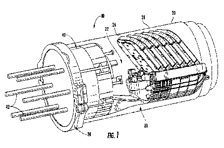
[0011] FIG. 1 is a perspective view of a butt
closure in accordance with
embodiments of the present disclosure;
[0012] FIG. 2 is a front perspective view of an
organizer assembly, with a
backplate in a closed position and a plurality of organizer trays in rear
positions, in
accordance with embodiments of the present disclosure;
[0013] FIG. 3 is a rear perspective view of an
organizer assembly, with a
backplate in a closed position and a plurality of organizer trays in rear
positions, in
accordance with embodiments of the present disclosure;
[0014] FIG. 4 is a top perspective view of an
organizer assembly, with organizer
trays removed to illustrate positioning assemblies, in accordance with
embodiments of
the present disclosure;
[0015] FIG. 5 is a cross-sectional view of an
organizer assembly, with organizer
trays in rear, intermediate, and forward positions, in accordance with
embodiments of
the present disclosure;
[0016] FIG. 6 illustrates an organizer assembly
interacting with an associated
positioning assembly to be selectively positioned in a rear position, in
accordance
with embodiments of the present disclosure;
[0017] FIG. 7 is a front perspective view of an
organizer assembly, with a
backplate in a closed position and a plurality of organizer trays in
intermediate
positions, in accordance with embodiments of the present disclosure;
[0018] FIG. 8 illustrates an organizer assembly
interacting with an associated
positioning assembly to be selectively positioned in an intermediate position,
in
accordance with embodiments of the present disclosure;
3
CA 03153783 2022-4-6
WO 2021/072025
PCT/US2020/054708
[0019] FIG. 9 is a front perspective view of an
organizer assembly, with a
backplate in a closed position and a plurality of organizer trays in forward
positions,
in accordance with embodiments of the present disclosure;
[0020] FIG. 10 illustrates an organizer assembly
interacting with an associated
positioning assembly to be selectively positioned in a forward position, in
accordance
with embodiments of the present disclosure;
[0021] FIG. 11 is a front perspective view of an
organizer assembly, with a
backplate in an open position, in accordance with embodiments of the present
disclosure;
[0022] FIG. 12 illustrates a hinge assembly
interacting with a backplate such that
the backplate is selectively positioned in an open position, in accordance
with
embodiments of the present disclosure;
[0023] FIG. 13 is a front perspective view of an
organizer assembly, with a
secondary basket rotated such that catch arms are inserted in slots defined in
a hinge
assembly, in accordance with embodiments of the present disclosure;
[0024] FIG. 14 is a perspective view of an
organizer tray with splice modules
installed therein in accordance with embodiments of the present disclosure;
[0025] FIG. 15 is a perspective view of an
organizer tray with splice modules
removed in accordance with embodiments of the present disclosure; and
[0026] FIG. 16 is a bottom perspective view of a
splice module in accordance
with embodiments of the present disclosure.
DETAILED DESCRIPTION
[0027] Reference now will be made in detail to
embodiments of the invention,
one or more examples of which are illustrated in the drawings. Each example is
provided by way of explanation of the invention, not limitation of the
invention. In
fact, it will be apparent to those skilled in the art that various
modifications and
variations can be made in the present invention without departing from the
scope or
spirit of the invention. For instance, features illustrated or described as
part of one
embodiment can be used with another embodiment to yield a still further
embodiment. Thus, it is intended that the present invention covers such
modifications
and variations as come within the scope of the appended claims and their
equivalents.
4
CA 03153783 2022-4-6
WO 2021/072025
PCT/US2020/054708
[0028] Referring now to FIGS. 1 through 16,
embodiments of butt closures 10 and
organizer assemblies in accordance with the present disclosure are provided.
Closures
in accordance with the present disclosure, and in particular the organizer
assemblies thereof, may advantageously provide improved routing and storage
features. Additionally or alternatively, closures 10 and organizer baskets
thereof in
accordance with the present disclosure may advantageously provide improved
features for securing and positioning organizer trays and backplates thereof
in a
variety of positions, thus advantageously allowing efficient and effective
fiber-
populating, splicing, etc. Additionally or alternatively, closures 10 and
organizer
baskets thereof in accordance with the present disclosure, and in particular
the splice
modules which may be utilized with such closures 10 and/or organizer baskets,
may
advantageously provide improved flexibility with respect to the types of
splices
and/or other components that can be held therein.
[0029] Referring now to FIG. 11, a closure 10 in
accordance with the present
disclosure includes a cover 20_ Cover 20 is generally a domed cover which
defines an
interior 22 and an opening 24 which provides access to the interior 22. Cover
20 may
include an inner surface 26 which defines the interior 22 and an opposing
outer
surface 28 which is exposed to the external environment.
[0030] An organizer assembly 30 may be insertable
into (and thus disposed
within) the interior 22, such as along a longitudinal axis of the closure 10.
Organizer
assembly 30 may include one or more organizer trays 300 and/or other suitable
components for facilitating transmission component connections. For example,
in the
case of use with fiber optic cables, splices between optical fibers thereof
may be
housed in the various splice trays.
[0031] A base 40 may be insertable at least
partially into (and thus disposed at
least partially within) the interior 22. In some embodiments, organizer
assembly 30
may be connected to the base 40, such that insertion of the base 40 causes
insertion of
the tray assembly 30 into the interior 22. Cables 42 may be inserted through
the base
40 into the interior 22, and connection between transmission elements thereof
(such as
optical fibers) may be made within the interior 22, such as in the organizer
trays 300
of the organizer assembly 30.
5
CA 03153783 2022-4-6
WO 2021/072025
PCT/US2020/054708
[0032] FIGS. 2 through 16 illustrate various
embodiments of organizer assemblies
30 and components thereof in accordance with embodiments of the present
disclosure.
A mutually orthogonal coordinate system may be defined for organizer
assemblies 30
in accordance with the present disclosure, and may include a mutually
orthogonal
longitudinal axis 102, lateral axis 104, and transverse axis 106.
[0033] Referring now to FIGS. 2 through 13,
organizer assemblies 30 in
accordance with the present disclosure may include a primary basket 110. The
primary basket 110 generally forms at least a portion of the base exterior of
the
organizer assembly 30, and includes an exterior surface 112 and an interior
surface
114. The primary basket 110 may extend along the longitudinal axis 102 between
a
first end 116 and a second end 118. The first end 116 may be an open end, as
shown,
such that cables 42 or transmission elements thereof being directed along and
parallel
to the longitudinal axis 102 can enter or exit an interior 120 of the primary
basket 110
through the first end 116. The second end 118 may be a closed end, as shown,
such
that cables 42 or transmission elements thereof being directed along and
parallel to
the longitudinal axis 102 cannot enter an interior 120 of the primary basket
110
through the second end 118, and instead encounter a surface of the primary
basket
110.
[0034] The primary basket 110 may further extend
along the lateral axis 104
between a first side 122 and a second side 124, both of which may be closed
(as
discussed above with respect to second end 118). In exemplary embodiments, a
length between the first end 116 and second end 118 is greater than a length
between
the first side 122 and the second side 124. Further, in exemplary embodiments,
transitions between the closed second end 118 portion and a base portion 126,
the
closed first side portion 122 and the base portion 126, the closed second side
portion
124 and the base portion 126, the closed second end 118 portion and closed
first side
portion 122, and/or the closed second end 118 portion and closed second side
portion
124 are curved.
[0035] Basket 110 may generally be utilized to
house excess cables 42 and/or
transmission elements thereof as the cables 42 and/or transmission elements
thereof
are routed through the closure 10 and organizer assembly 30 thereof
6
CA 03153783 2022-4-6
WO 2021/072025
PCT/US2020/054708
[0036] Primary basket 110 may further include an
upper peripheral lip 128, which
may extend between the first end 116 and second end 118, such as on the sides
122,
124, and may further extend between the sides 122, 124, such as along the
closed
second end 118. For example, the lip 128 may extend along an upper edge (along
the
traverse axis 106) of the primary basket 110, such as along the sides 122, 124
and
second end 118_
[0037] A connector shaft 138 may extend from the
first end 116 along the
longitudinal axis 102, such that at least a portion of the connector shaft 138
is exterior
to the primary basket 110. The connector shaft 138 may connect to the base 40,
thus
connecting the organizer assembly 30 and base 40 together.
[0038] Organizer assemblies 30 in accordance with
the present disclosure may
further include a backplate 140. Backplate 140 may be rotatably connected to
the
primary basket 110, such as by a hinge assembly as discussed herein. Backplate
140
may be rotatable relative to the primary basket 110, such as at the hinge
assembly. In
exemplary embodiments, the backplate 140 may be rotatable about the lateral
axis
104. In exemplary embodiment the backplate 140 may be selectively positionable
in
one of a plurality of rotatable positions, as discussed herein. For example,
in
exemplary embodiments, backplate 140 may be rotatable between a closed
position,
as illustrated in FIGS. 2 through 10, and an open position, as illustrated in
FIGS. 11
through 13. In the closed position, the backplate 140 may extend (from a rear
end to a
front wall thereof as discussed herein) along the longitudinal axis 102. In
the open
position, the backplate 140 may extend (from the rear end to the front wall
thereof)
along the transverse axis 106.
[0039] Backplate 140 may be positioned above the
primary basket 110 along the
transverse axis 106. For example, in exemplary embodiments, backplate 140 may
be
entirely above the primary basket 110. As illustrated in FIGS. 2 through 10,
in some
embodiments, the backplate 140 when selectively positioned in the closed
position,
contacts the primary basket 140, such as the peripheral lip 128 thereof
[0040] Backplate 140 may include a base wall 142, a
first sidewall 144, a second
sidewall 146, and a front wall 148, and a rear wall 150. First sidewall 144
and second
sidewall 146 may be spaced apart along the lateral axis 104. Front wall 148
and rear
wall 150 may be spaced apart (such as along the longitudinal axis 102 when in
the
7
CA 03153783 2022-4-6
WO 2021/072025
PCT/US2020/054708
closed position or along the transverse axis 106 when in the open position).
Backplate may thus extend between the sidewalls 146, 148 along the lateral
axis 104
and between the front and rear walls 148, 150, such as along the longitudinal
axis 102
when in the closed position or along the transverse axis 106 when in the open
position.
100411 A plurality of entry/exit slots 152 may be
defined at and through the rear
wall 150, such as proximate the first sidewall 144 and/or second sidewall 146.
Cables
42 or transmission elements thereof can enter or exit an interior of the
backplate 140
through the exntry/exit slots 152. In some embodiments, one or more plugs 154
are
provided. Each plug 154 may be removably inserted into one of the entry/exit
slots
152 to secure cables 42 or transmission elements extending through the
entry/exit
slots 152 therein. In exemplary embodiments, plugs 154 may be formed from a
rubber.
100421 Retainer tabs 156 may extend into the
interior of the backplate from the
first sidewall 144, second sidewall 146, front wall 148, and/or base wall 142
(e.g.
proximate the first sidewall 144, second sidewall 146, and/or front wall 148)
to guide
and retain such cables 142 or transmission elements thereof
100431 An organizer assembly 30 in accordance with
the present disclosure may
further include a hinge assembly 160 which connects the backplate 140, such as
at the
rear wall 150 thereof, to the primary basket 110, such as at the first end 116
thereof
Backplate 140 may be rotatable relative to the primary basket 110 at the hinge
assembly 160, such as about the lateral axis 104.
100441 Hinge assembly 160 may, for example, include
latch 162 which rotatable
receives an axle 164 of the backplate 140. The axle 164 may, for example, be
connected to the rear wall 150 of the backplate 140. Hinge assembly 160 may
further
include a base 166 which extends, such as along the transverse axis 106, from
the
basket 110 (such as at the first end 116 thereof). The latch 162 may extend
from the
base 166.
100451 In some embodiments, base 166 may be formed
from multiple
components, such as a basket component 166' and a backplate component 166".
Basket component 166' may, for example, be integral with the basket 110 such
that
they are formed as a single, unitary structure. Backplate component 166" may
be
8
CA 03153783 2022-4-6
WO 2021/072025
PCT/US2020/054708
connected to the basket component 166' to form the base 166. Alternatively,
the base
166 may be a single, unitary structure, which may for example be integral with
the
basket 110 such that they are formed as a single, unitary structure.
[0046] As discussed, the backplate 140 is
selectively positionable in one of a
plurality of rotatable positions, such as an open position and a closed
position. In
exemplary embodiments, the hinge assembly 160 may include a catch 168 which is
selectively insertable into a slot 170 of the backplate 140. Catch 168 may
extend,
such as along the transverse axis 106, from the base 166. Slot 170 may, for
example,
be defined in a tab 172 which extend from the rear wall 150 of the backplate
140. In
exemplary embodiments, when the backplate 140 is positioned in the open
position,
the catch 168 may be inserted in the slot 170. Such interaction of the catch
168 with
the slot 170 may selectively position and secure the backplate 140 in the open
position. Additionally, in the open position the backplate 140 may be spaced
from the
basket 110, such as from the peripheral lip 128 thereof. When the backplate
140 is
positioned in the closed position, the catch 168 may be removed from the slot
170,
and may contact the basket 110, such as the peripheral lip 128 thereof
[0047] As shown in FIGS, 5 and 11 through 13,
organizer assemblies 30 in
accordance with the present disclosure may include a second basket 180 which
may
be rotatably and removably connectable to the hinge assembly 160. The
secondary
basket 180 as shown is rotatably connected to the hinge assembly 160. In
exemplary
embodiments, the secondary basket 180 may be connected to the hinge assembly
160
below the below the backplate 140 along the transverse axis 106, such as
between the
backplate 140 and the interior surface 114 of the primary basket 110 along the
transverse axis 106. The secondary basket 180 may be rotatable between a first
position wherein the secondary basket 180 is aligned along the longitudinal
axis 102
(as shown in FIGS. 5, 11, and 12) and a second position wherein the secondary
basket
180 is aligned at an angle between the longitudinal axis 102 and transverse
axis 106
(as shown in FIG. 13). In exemplary embodiments, the secondary basket 180 may
be
removable, such that it can be utilized as needed for cable 42 (and
transmission
elements thereof) routing and set aside/discarded when not needed.
[0048] The secondary basket 180 includes an
exterior surface 182 and an interior
surface 184. The secondary basket 180 may extend (such as along the
longitudinal
9
CA 03153783 2022-4-6
WO 2021/072025
PCT/US2020/054708
axis 102 when in the first position) between a first end 186 and a second end
188.
The first end 186 may be an open end, as shown, such that cables 42 or
transmission
elements thereof being directed along and parallel to the longitudinal axis
102 can
enter or exit an interior 190 of the secondary basket 180 through the first
end 186,
when the secondary basket 180 is in the first position. The second end 188 may
be a
closed end, as shown, such that cables 42 or transmission elements thereof
being
directed along and parallel to the longitudinal axis 102 cannot enter an
interior 190 of
the secondary basket 180 through the second end 188, and instead encounter a
surface
of the primary basket 110, when the secondary basket 180 is in the first
position.
[0049] The secondary basket 180 may further extend
along the lateral axis 104
between a first side 192 and a second side 194, both of which may be closed
(as
discussed above with respect to second end 118). In exemplary embodiments, a
length between the first end 186 and second end 188 is greater than a length
between
the first side 182 and the second side 184. Further, in exemplary embodiments,
transitions between the closed second end 188 portion and a base portion 196,
the
closed first side portion 192 and the base portion 196, the closed second side
portion
194 and the base portion 196, the closed second end 188 portion and closed
first side
portion 192, anclVor the closed second end 188 portion and closed second side
portion
194 are curved.
[0050] In exemplary embodiments, the area of the
interior 190 may be less than
the area of the interior 120, the length between the first end 186 and second
end 188
may be less than the length between the first end 116 and second end 118,
and/or the
length between the first side 182 and second side 184 is less than the length
between
the first side 122 and second side 124, such that the secondary basket 180 can
fit at
least partially, and in some embodiments fully, within the primary basket 110
(such as
the interior 120 thereof).
[0051] Secondary basket 180 may further include an
upper peripheral lip 198,
which may extend between the first end 186 and second end 188, such as on the
sides
192, 194, and may further extend between the sides 192, 194, such as along the
closed
second end 188. For example, the lip 198 may extend along an upper edge (along
the
traverse axis 106) of the secondary basket 180, such as along the sides 192,
194 and
second end 188.
CA 03153783 2022-4-6
WO 2021/072025
PCT/US2020/054708
[0052] In some embodiments, basket 180 may further
include a plurality of
retainer tabs 200, each of which extends from the basket 180 into the interior
190.
The tabs 200 may be connected to the basket 180 at the upper edge of the
basket 180,
such as adjacent the lip 198. Tabs 200 may generally assist in routing and
retaining
cables 42 and transmission elements in the interior 190 during assembly,
splicing,
etc., thereof.
[0053] One or more connector arms 204 may extend
from the first end 186 (such
as along the longitudinal axis 102 when the secondary basket 180 is in the
first
position). The connector arms 204 may be removably connected to the hinge
assembly 160, such as the base 166 thereof, thus rotatably connecting the
secondary
basket 180 thereto. For example, protrusions 206 provided on the arms 204 may
be
inserted in depressions 208 defined in the base 166 to rotatably connect the
secondary
basket 180 thereto.
[0054] In some exemplary embodiments, the secondary
basket 180 may further
include one or more catch arms 210. Catch arms 210 may, for example, extend
from
the first end 186. Each catch arm 210 may be selectively insertable into a
slot 212
defined in the hinge assembly 160, such as in the base 166. For example, in
the first
position, the catch arms 210 may be removed from the slots 212. In the second
position, the catch arms 210 may be inserted into the slots 212. Positioning
of the
catch arms 210 in the slots may allow the secondary basket 180 to be
selectively
positioned in the second position.
[0055] Referring now generally to FIGS. 2through
14, organizer assemblies 30 in
accordance with the present disclosure may further include one or more
organizer
trays 300, such as in exemplary embodiments a plurality of organizer trays
300.
[0056] Each organizer tray 300 is rotatably
connectable, and thus may be
rotatably connected, to the backplate 140, such as to a positioning assembly
of the
backplate 140 as discussed herein. Each organizer tray 300 may be rotatable,
such as
about the lateral axis 104. Further, in exemplary embodiments, each organizer
tray
300 may be selectively positionable in one of a plurality of rotational
positions, such
as in some embodiments at least three rotational positions. For example, each
organizer tray 300 may in some embodiments be selectively positioned in a rear
11
CA 03153783 2022-4-6
WO 2021/072025
PCT/US2020/054708
position (see FIGS. 2 through 6, an intermediate position (see FIGS. 5 and 7
through
8), or a forward position (see FIGS. 5 and 9 through 10).
[0057] Each organizer tray 300 may include a main
body 302. Main body 302
may, for example, include a base wall 304, a first sidewall 306, a second
sidewall 308,
a front wall 310, and a rear wall 312. First sidewall 306 and second sidewall
308 may
be spaced apart along the lateral axis 104 Front wall 310 and rear wall 312
may be
spaced apart (such as along tan axis transverse to the lateral axis 104).
Openings 213
may be defined in the rear wall 312, such that cables 42 or transmission
elements
enter or exit an interior 314 of the organizer tray 300 through the rear wall
312 (e.g.
through the openings 213).
[0058] Each organizer tray 300 may further include
one or more features for
guiding and retaining cables 142 or transmission elements as they are routed
through
and within the organizer trays 300. For example, one or more routing channels
320
may be defmed in the interior 314. A routing channel 320 may, for example, be
defined at the front wall 310 and/or rear wall 312. Further, such routing
channels 320
may extend to be defined at neighboring portions of the first sidewall 306
and/or
second sidewall 308. Additionally or alternatively, one or more routing
channels 320
may be defined between neighboring module mounting locations, as discussed
herein.
[0059] Additionally or alternatively, retainer tabs
322 may extend into the interior
314 and, in some embodiments, into one or more routing channels 320, from the
first
sidewall 306, second sidewall 308, front wall 310, rear wall 312, and/or
internal walls
defining the routing channels 320 to guide and retain such cables 42 or
transmission
elements thereof
[0060] As discussed, and with reference
specifically to FIG. 4, backplate 140 may
include a plurality of positioning assemblies 250. The positioning assemblies
250
may, for example, be disposed in a linear array which extends along the
longitudinal
axis 102 when the backplate 140 is in the closed position. The positioning
assemblies
250 may be disposed on the base wall 142. Each organizer tray 300 may be
rotatably
connected to the backplate 140 at one of the plurality of positioning
assemblies 250.
Further, each positioning assembly 250 may cause a connected organizer tray
300 to
be selectively positionable in one of a plurality of rotational positions,
such as a rear,
intermediate, or forward position as discussed herein.
12
CA 03153783 2022-4-6
WO 2021/072025
PCT/US2020/054708
[0061] Each positioning assembly 250 may, for
example, include one or more
connector protrusions 252 which are insertable into depressions 254 defined in
an
associated organizer tray 300. Such depressions 254 may, for example, be
defined in
arms 256 which extend from the body 302 of the organizer tray 300, such as
from or
at the rear wall 312. The interaction between the depressions 254 and
protrusions 252
may rotatably connect the organizer trays 300 to the positioning assemblies
250.
[0062] Each positioning assembly 250 may, for
example, include a channel block
260 which defines a plurality of channels 261 Each channel 262 may correspond
to
one of the plurality of rotational positions in which a connected organizer
tray 300
may be positioned. The channels 262 may, for example, each extend along the
lateral
axis 104. Further, the channels 262 may be disposed in a linear array which
extends
along the longitudinal axis 102 when the backplate is in the closed position.
Each
organizer tray 300 may include a positioning tab 330. The positioning tab 330
may,
for example, extend from the body 302 of the organizer tray 300, such as from
or at
the rear wall 312. A positioning tab 330 of an organizer tray 300 may be
selectively
inset-table into one of the plurality of channels 262 in a channel block 260
of an
associated positioning assembly 250. Insertion of the positioning tab 330 into
one of
the plurality of channels 262 may correspond with selective positioning of the
organizer tray 300 in one of the plurality of positions. For example, FIG. 6
illustrates
positioning tab 330 inserted in a forward channel 262, which corresponds to
selective
positioning of the associated organizer tray 300 in a rear position. FIG. 8
illustrates
positioning tab 330 inserted in an intermediate channel 262, which corresponds
to
selective positioning of the associated organizer tray 300 in an intermediate
position.
FIG. 10 illustrates positioning tab 330 inserted in an rear channel 262, which
coilesponds to selective positioning of the associated organizer tray 300 in a
forward
position.
[0063] Referring now in particular to FIGS. 14
through 16, each organizer tray
300 may generally accommodate one or more splice modules 350. Each splice
module 350 may be removable connected to the organizer tray 300, such as to
the
base wall 304 thereof For example, base wall 304 may include a plurality of
module
mounting locations 340. In exemplary embodiments as shown, the module mounting
13
CA 03153783 2022-4-6
WO 2021/072025
PCT/US2020/054708
locations 340 may be aligned in a linear array, and a routing channel 320 may
be
defined between neighboring mounting locations 340 in the linear array.
[0064] In exemplary embodiments, each of the module
mounting locations 340
may include a plurality of leg slots 342 which may be defined through the base
wall
304 and one or more pluralities of positioning slots 344 which may be defined
through the base wall 304. The leg slots 342 may, for example, define at least
a
portion of a periphery of the module mounting location 340, and may for
example, be
disposed at corners of the module mounting location 340, Each plurality of
positioning slots 344 may be defined within the periphery of the module
mounting
location 340, and may for example extend in a linear array. The leg slots 342
and
positioning slots 344 may generally facilitate removable connection of a
splice
module 350 to the organizer tray at a module mounting location 340.
[0065] Each splice module 350 may, for example,
include a base 352 and a
plurality of legs 354 extending from the base 352, such as below the base 352
as
shown. The legs 354 may further extend from and at least partially define a
periphery
of the base 352, and may further be disposed at corners of the base 352. To
removably connect a splice module 350 to an organizer tray 300 at a module
mounting location 340, each leg 354 may be inserted into one of the leg slots
342 of a
module mounting location 340. Further, a splice module 350 may include one or
more cantilevered arms 356 extending from the base 352, such as below the base
352
as shown. Each cantilevered arm 356 may include a tab 358 at a distal end
thereof
To removably connect a splice module 350 to an organizer tray 300 at a module
mounting location 340, the cantilevered arm 356, such as the tab 358 thereof,
may be
inserted in one of a plurality of positioning slots 344 of a module mounting
location
340.
[0066] In exemplary embodiments, a splice module
350 may be removably
connectable to an organizer tray 300, such as at a module mounting location
340, in
multiple different orientations. For example, the plurality of positioning
slots 344
may be oriented such that the cantilevered arm 356, such as the tab 358
thereof, may
be inserted in a different one of a plurality of positioning slots 344
depending on the
orientation of the splice module 350.
14
CA 03153783 2022-4-6
WO 2021/072025
PCT/US2020/054708
[0067] Splice modules 350 in accordance with the
present disclosure may
advantageously be dual material components. For example, splice modules 350
may
further include one or more overmolded portions 360 which are disposed on
portions
of the base 352, such as on a lower surface and sidewalls thereof The
overmolded
portions 360 advantageously provide improved structural integrity, rigidity,
and
protection. The base 352, as well as the legs 354 and cantilevered arms 356
thereof,
may for example, be formed from a hard plastic such as polycarbonate or nylon.
The
overmolded portions 364) may be formed from suitable elastomers, such as
vulcanized
elastomers.
[0068] Splice modules 350 in accordance with the
present disclosure may further
include a plurality of partitions 362, each of which may extend from the base
352.
The partitions 362 may be generally parallel to each other, and neighboring
partitions
362 may define channels 364 therebetween. Each channel 364 may define and
extend
along a longitudinal channel axis 365, as shown. Further, one or more arms 366
may
extend from one or more of the neighboring partitions 362 into one or more of
the
channels 364 defined by such neighboring partitions 362. Such arms 366 may
extend
into the channels 364 at an angle to the longitudinal channel axis 365, as
shown. For
example, a first partition 362' of neighboring partitions 362 may include one
or more
arms 366 extending into a channel 364 defined by the neighboring partitions
362, and
a second partition 362" of neighboring partitions 362 may include one or more
arms
366 extending into the channel 364 defined by the neighboring partitions 362.
Further, in exemplary embodiments as shown, the one or more arms 366 extending
into a channel 364 from a first partition 362' may extend in a direction
opposite the
direction of the one or more arms 366 extending into the channel 364 from a
second
partition 362".
[0069] In exemplary embodiments, partitions 362
and arms 366 of splice modules
350 may be formed from suitable elastomers, such as vulcanized elastomers.
[0070] Splice modules 350 in accordance with the
present disclosure, and in
particular the configuration of the partitions 362 and arms 366, are
particularly
advantageous due to their versatility and flexibility in accommodating various
components. For example, a channel 364 of a splice module 350 may be capable
of
holding triple-stacked single spliced transmission elements, double-stacked
ribbon
CA 03153783 2022-4-6
WO 2021/072025
PCT/US2020/054708
spliced transmission elements, mechanical splices, splitter modules from 1:2
to 1:32,
PLCs, etc.
[0071] This written description uses examples to
disclose the invention, including
the best mode, and also to enable any person skilled in the art to practice
the
invention, including making and using any devices or systems and performing
any
incorporated methods. The patentable scope of the invention is defined by the
claims,
and may include other examples that occur to those skilled in the art. Such
other
examples are intended to be within the scope of the claims if they include
structural
elements that do not differ from the literal language of the claims, or if
they include
equivalent structural elements with insubstantial differences from the literal
languages
of the claims.
16
CA 03153783 2022-4-6