Note: Descriptions are shown in the official language in which they were submitted.
89999793
SPRAY GUN ALIGNMENT FOR PRECISION APPLICATION
OF CONTAINER COATINGS
100011 This application is being filed on July 1, 2021, as a PCT
International Patent
Application and claims the benefit of and priority to U.S. Provisional Patent
Application
No. 63/047,019 filed on July 1, 2020.
BACKGROUND
100021 It is often beneficial to apply coatings to containers. For
example, aluminum
food and beverage cans are coated on interior surfaces with a liner that forms
a protective
barrier between the food or beverage product and the metal. Similarly,
coatings are also
commonly applied to other types of containers for storage of products other
than food and
beverages.
100031 Spray machines can rapidly and effectively apply coatings to
containers by
spraying the coating using a spray gun, but the alignment between the spray
gun and the
container is critical to forming a proper protective barrier. Even a small
misalignment of
the spray gun can result in improper application, and therefore highly skilled
operators are
required to properly align the spray gun. To further complicate matters,
different coatings
require different spray gun setups, and therefore the alignment must be
reconfigured each
time a different coating is introduced.
100041 Spray machines are also used in other applications, such as for
spraying general
industrial liquids (e.g. for metal cabinets, machine parts, appliances),
industrial wood
coatings and treatments (e.g. for kitchen cabinets and furniture), powder
coatings, and in
automotive interiors.
SUMMARY
100051 In general terms, this disclosure is directed to spray gun
alignment, In one
possible configuration and by non-limiting example, a spray gun is aligned for
precision
application of liquid or power container coatings. Various aspects are
described in this
disclosure, which include, but are not limited to, the following aspects.
100061 One aspect is a spray gun alignment jig for aligning a spray gun
with a
container holder of a container spray machine, the spray gun alignment jig
comprising: a
container holder adapter that engages with a container holder of the container
spray
1
Date Recue/Date Received 2022-11-11
WO 2022/006450
PCT/US2021/040175
machine; a spray gun adapter that engages with the spray gun; and a linkage
that connects
the spray gun adapter and the container holder adapter in a predetermined
alignment.
100071 Another aspect is the spray gun alignment jig, wherein
the linkage includes a
releasable joint that is releasable to separate the container holder adapter
from the spray
gun adapter.
[0008] A further aspect is the spray gun alignment jig,
wherein the container holder
adapter is sized to fit within the container holder of the container spray
machine and
further comprises an orientation guide that causes the container holder
adapter to fit within
the container holder in a particular orientation.
[0009] Yet another aspect is the spray gun alignment jig,
wherein the container holder
is part of a container spinner of a container transporter of the container
spray machine.
[0010] Another aspect is the spray gun alignment jig, wherein
the spray gun adapter
includes a tip alignment receptacle that receives the tip of the spray gun to
align the spray
gun adapter with the tip of the spray gun.
[0011] A further aspect is the spray gun alignment jig,
wherein the predetermined
alignment includes a predetermined position and a predetermined orientation.
[0012] Yet another aspect is the spray gun alignment jig,
wherein the predetermined
position comprises: a forward/backward position; a left/right position; and an
up/down
position.
[0013] Another aspect is the spray gun alignment jig, wherein
the predetermined
orientation comprises: a pitch; a roll; and a yaw.
[0014] A further aspect is the spray gun alignment jig,
wherein the predetermined
alignment causes the spray gun to spray an interior coating that conforms to
at least one
interior coating criterion.
[0015] Yet another aspect is the spray gun alignment jig,
wherein the at least one
interior coating criterion is selected from: an amount of an interior surface
that is coated, a
thickness of the interior coating, an amount of interior surface that is
exposed, and an
electrical resistance of the interior coating.
[0016] Another aspect is the spray gun alignment jig that is
configured to align the
spray gun with the container in a predetermined orientation selected for
applying an
interior coating to the container, the interior coating being one of: a
sprayable water-borne
coating composition, a sprayable organic-solvent-based coating composition,
and a
sprayable powder coating composition.
2
CA 03154049 2022-4-7
89999793
[0017] A further aspect is the spray gun alignment jig, wherein the
interior coating
further comprises one or more film-forming components selected from: latex
emulsions,
organic solution polymerized acrylic polymers, polyester polymers, polyether
polymers,
polyether-acrylate polymers, polyester-acrylate polymers, polyolefin polymers,
and
copolymers and combinations thereof.
100131 Yet another aspect is the spray gun alignment jig, wherein the
spray gun
alignment jig is configured to align the spray gun based on at least one
coating
characteristic selected from a viscosity of the coating, a theology of the
coating, and a
draping of the coating.
[0019] Another aspect is the spray gun alignment jig that is configured
to align the
spray gun with a container holder to spray a coating selected from the group
consisting of:
an INNOVEL HPSTM series of water-borne acrylic beverage can inside spray
product; an
INNOVEL MAXTM internal spray lacquer product; an INNOVEL VCLTM clear internal
spray
product; a NUTRISHEILD SOLISTATm non-BPA internal spray product; a PPG6100TM
internal gold and aluminized spray coating product; a PPG 6150TM internal gold
and
aluminized spray coating product; an AQUALURE GI 5OTM beverage can inside
spray
product; a VALPURETM acrylic and poly ether-acrylic beverage can inside spray
non-BPA
product; a VALPURETM polyether-acrylic and polyester two-piece D8cI food can
inside
spray non-BPA product; a CANVERA 1110 TM beverage can inside spray product;
and a
CANVERA 3110Im food can internal spray product
[0020] Another aspect is a method of aligning a spray gun of a
container spray
machine, the container spray machine having a container holder for holding a
container
during spraying, the method comprising: arranging a container holder adapter
of a spray
gun alignment jig onto the container holder; arranging a spray gun adapter
onto the spray
gun; and aligning the spray gun with respect to the container holder as
indicated by the
spray gun alignment jig.
[0021] A further aspect is a method of aligning the spray gun, further
comprising
generating the spray gun alignment jig by: generating a three-dimensional
model of the
container holder adapter, a configuration of the container holder adapter
being selected to
engage with the container holder of the container spray machine; generating a
three-
dimensional model of the spray gun adapter, a configuration of the spray gun
adapter
being selected to engage with the spray gun of the container spray machine;
generating a
three-dimensional model of a linkage that extends between the container holder
adapter
and the spray gun adapter to arrange the spray gun adapter in a predetermined
alignment
3
Date Recue/Date Received 2022-11-11
89999793
with respect to the container holder adapter; and using the three-dimensional
models of the
container holder adapter, spray gun adapter, and linkage to generate the spray
gun
alignment jig having the container holder adapter, spray gun adapter, and
linkage.
100221 Another aspect is the method of aligning the spray gun, further
comprising:
applying a coating to the container after aligning the spray gun of the
container spray
machine.
100231 Yet another aspect is the method of aligning the spray gun,
wherein the
alignment is selected for spraying a coating comprising at least one of: a
sprayable water-
borne coating composition, a sprayable organic-solvent-based coating
composition, and a
sprayable powder coating composition.
100241 A further aspect is the method of aligning the spray gun,
wherein the alignment
is selected for spraying a coating selected from the group consisting of: an
INNOVEL HPSTM
series of water-borne acrylic beverage can inside spray product; an INNOVEL
MAX TM
internal spray lacquer product; an INNOVEL VCLTM clear internal spray product;
a
NUTRISHEILD SOLISTATm non-BPA internal spray product; a PPG6IOOTM internal
gold and
aluminized spray coating product; a PPG 6150TM internal gold and aluminized
spray coating
product; an AQUALURE G1 5QTM beverage can inside spray product; a VALPURETM
acrylic
and polyether-acrylic beverage can inside spray non-BPA product; a VALPURETM
polyether-acrylic and polyester two-piece D&I food can inside spray non-BPA
product; a
CANVERA 1110Tm beverage can inside spray product; and a CANVERA 3110Tm food
can
internal spray product,
100251 Yet another aspect is a method of generating a spray gun
alignment jig for
aligning a spray gun of a container spray machine, the method comprising:
generating a
three-dimensional model of a container holder adapter, a configuration of the
container
holder adapter being selected to engage with a container holder of the
container spray
machine; generating a three-dimensional model of a spray gun adapter, a
configuration of
the spray gun adapter being selected to engage with the spray gun of the
container spray
machine; generating a three-dimensional model of a linkage that extends
between the
container holder adapter and the spray gun adapter to arrange the spray gun
adapter in a
predetermined alignment with respect to the container holder adapter, and
using the three-
dimensional models of the container holder adapter, spray gun adapter, and
linkage to
generate the spray gun alignment jig having the container holder adapter,
spray gun
adapter, and linkage.
4
Date Recue/Date Received 2022-11-11
89999793
[0026] Another aspect is the method of generating a spray gun alignment
jig, wherein
using the three-dimensional models to generate the spray gun alignment jig
comprises
sending instructions to a 3D printer.
[0027] A further aspect is the method of generating a spray gun
alignment jig, wherein
generating the spray gun alignment jig comprises printing the spray gun
alignment jig with
a 3D printer.
[0028] Another aspect is the method of generating a spray gun alignment
jig, further
comprising: receiving input from a user defining predetermined measurements
between
the spray gun and the container holder; and using the input to generate the
three-
dimensional model of the linkage with the predetermined alignment.
[0029] Yet another aspect is the method of generating a spray gun
alignment jig,
further comprising: receiving a selection of a coating or type of coating to
be applied to a
container by the container spray machine; selecting from a database
measurements
identifying the predetermined alignment based on the coating or type of
coating; and using
the measurements to generate the three-dimensional model of the linkage with
the
predetermined alignment.
[0030] A further aspect is the method of generating a spray gun
alignment jig, wherein
the spray gun alignment jig is configured to align the spray gun of the
container spray
machine to spray a coating comprising at least one of: a sprayable water-borne
coating
composition, a sprayable organic-solvent-based coating composition, and a
sprayable
powder coating composition.
[0031] Another aspect is the method of generating a spray gun alignment
jig, wherein
the spray gun alignment jig is configured to align the spray gun of the
container spray
machine to spray a coating selected from the group consisting of: an 1NNOVEL I-
IPSTM
series of water-borne acrylic beverage can inside spray product; an INNOVEL
MAXTM
internal spray lacquer product; an INNOVEL VCLTM clear internal spray product;
a
NUTRISHEILD SOLISTATm non-BPA internal spray product; a PPG6IOOTM internal
gold
and aluminized spray coating product; a PPG 6150TM internal gold and
aluminized spray
coating product; an AQUALURE Gl 5OTM beverage can inside spray product; a
VALPURETM
acrylic and polyether-acrylic beverage can inside spray non-BPA product; a
VALPURETM
polyether-acrylic and polyester two-piece Ded food can inside spray non-BPA
product; a
CANVERA 1110Tm beverage can inside spray product; and a CANVERA 3I1OTM food
can
internal spray product.
Date Recue/Date Received 2022-11-11
89999793
[0032] A further aspect is at least one computer readable storage device
storing data
instructions that, when executed by at least one processing device, cause the
at least one
processing device to perform operations comprising: receive input identifying
a predetermined
alignment of a spray gun with respect to a container holder of a container
spray machine; and
generate a three-dimensional model of a spray gun alignment jig comprising: a
container holder
adapter that engages with a container holder of the container spray machine; a
spray gun adapter
that engages with the spray gun; and a linkage that connects the spray gun
adapter to the
container holder adapter with the predetermined alignment.
[0033] Another aspect is the at least one computer readable storage
device, wherein the
instructions further cause the at least one processing device to: receive
input identifying a spray
gun type; and generate the three-dimensional model of the spray gun adapter
based on the spray
gun type.
[0034] Yet another aspect is the at least one computer readable storage
device, wherein the
instructions further cause the at least one processing device to: receive
input identifying a
container spray machine type; and generate the three-dimensional model of the
container holder
adapter based on the container spray machine type.
[0035] A further aspect is the at least one computer readable storage
device, wherein the
instructions further cause the at least one processing device to: generate the
three-dimensional
model of the linkage, wherein the linkage includes a body, the body being
sized and shaped to
connect the three-dimensional model of the container holder adapter to the
three-dimensional
model of the spray gun.
[0036] Another aspect is the at least one computer readable storage
device, wherein
generating the three-dimensional model of the linkage further comprises
defming the size and
shape of the body to avoid interference with components of the container spray
machine based
on the container spray machine type.
[0036a] In particular embodiments, the present disclosure relates to:
- a spray gun alignment jig for aligning a spray gun with a
container holder of a
container spray machine, the container spray machine configured to spray a
liquid coating, the
spray gun of the container spray machine having an adjustable position and
orientation, the spray
gun alignment jig comprising: a container holder adapter that is sized and
configured to fit within
a container holder of the container spray machine; a spray gun adapter that
engages with the
spray gun; and a linkage that connects the spray gun adapter and the container
holder adapter in a
predetermined alignment;
6
Date Regue/Date Received 2022-11-11
89999793
- a method of aligning a spray gun of a container spray machine,
the container
spray machine configured to spray a liquid coating and having a container
holder for holding a
container during spraying, the spray gun of the container spray machine having
an adjustable
position and orientation, the method comprising: arranging a container holder
adapter of a spray
gun alignment jig onto the container holder, the container holder adapter
being sized and
configured to fit within the container holder; arranging a spray gun adapter
onto the spray gun;
and aligning the spray gun with respect to the container holder as indicated
by the spray gun
alignment jig;
- a method of generating a spray gun alignment jig for aligning a
spray gun of a
container spray machine, the container spray machine configured to spray a
liquid coating, the
spray gun of the container spray machine having an adjustable position and
orientation, the
method comprising: generating a three-dimensional model of a container holder
adapter, a
configuration of the container holder adapter being selected to be sized and
configured to fit
within a container holder of the container spray machine; generating a three-
dimensional model
of a spray gun adapter, a configuration of the spray gun adapter being
selected to engage with the
spray gun of the container spray machine; generating a three-dimensional model
of a linkage that
extends between the container holder adapter and the spray gun adapter to
arrange the spray gun
adapter in a predetermined alignment with respect to the container holder
adapter; and using the
three-dimensional models of the container holder adapter, spray gun adapter,
and linkage to
generate the spray gun alignment jig having the container holder adapter,
spray gun adapter, and
linkage; and
- at least one computer readable storage device storing data
instructions that, when
executed by at least one processing device, cause the at least one processing
device to perform
operations comprising: receive input identifying a predetermined alignment of
a spray gun with
respect to a container holder of a container spray machine, the container
spray machine
configured to spray a liquid coating, the spray gun of the container spray
machine having an
adjustable position and orientation; and generate a three-dimensional model of
a spray gun
alignment jig comprising: a container holder adapter that is sized and
configured to fit within a
container holder of the container spray machine; a spray gun adapter that
engages with the spray
gun; and a linkage that connects the spray gun adapter to the container holder
adapter with the
predetermined alignment.
6a
Date Regue/Date Received 2022-11-11
89999793
BRIEF DESCRIPTION OF THE DRAWINGS
[0037] FIG. 1 is a schematic block diagram of an example spray gun
alignment system
according to the present disclosure.
[0038] FIG. 2 is a flow chart illustrating an example method of aligning
a spray gun of a
container spray machine.
[0039] FIG. 3 is a schematic diagram illustrating an example of a spray
machine of the
system shown in FIG. 1.
6b
Date Regue/Date Received 2022-11-11
WO 2022/006450
PCT/US2021/040175
[0040] FIG. 4 illustrates another example of the spray machine
shown in FIG. 3.
[0041] FIG_ 5 is a schematic block diagram illustrating an
example alignment of a
spray gun with a container C and container holder of an example spray machine.
[0042] FIG. 6 is a schematic diagram illustrating the
orientation of the spray gun.
[0043] FIG. 7 is a schematic block diagram illustrating an
example of the spray gun
alignment jig generator for generating a spray gun alignment jig.
[0044] FIG. 8 illustrates an exemplary architecture of a
computing device that can be
used to implement aspects of the present disclosure.
[0045] FIG_ 9 is a schematic block diagram illustrating an
example alignment jig
generator interface, which can be used to collect alignment measurements from
an
operator.
[0046] FIG. 10 is a schematic block diagram illustrating an
example of the alignment
database.
[0047] FIG. 11 is a flow chart illustrating an example method
of generating a spray
gun alignment jig.
[0048] FIG. 12 is a flow chart illustrating an example method
of generating a digital
model of the alignment jig 108.
[0049] FIG. 13 is a schematic block diagram illustrating an
example of the model
elements database.
[0050] FIG_ 14 is a schematic diagram illustrating an example
digital model of a
container holder adapter.
[0051] FIGS. 15 is a rear perspective view of a digital model
of the spray gun adapter_
[0052] FIG. 16 is a side perspective view of the digital model
of the spray gun adapter
shown in FIG. 15.
[0053] FIG. 17 is a schematic diagram illustrating the
alignment of the digital model
of the container holder adapter with the digital model of the spray gun
adapter in the
model space.
[0054] FIG. 18 is a schematic diagram illustrating the
generation of a digital model of
the linkage in the model space.
[0055] FIG. 19 is a schematic diagram further illustrating the
generation of the digital
model of the linkage in the model space.
[0056] FIG. 20 is a front view of an example jig fabrication
machine, and more
specifically an example of a 3D printer for printing the spray gun alignment
jig.
7
CA 03154049 2022-4-7
WO 2022/006450
PCT/US2021/040175
[0057] FIG. 21 is a perspective view of an example of the
physical spray gun
alignment jig.
[0058] FIG. 22 is a flow chart illustrating an example method
of aligning a spray gun
using a spray gun alignment jig.
[0059] FIG. 23 is a perspective view illustrating a portion of
an example container
transporter of a spray machine, and further illustrating the container holder
adapter portion
of the spray gun alignment jig.
[0060] FIG. 24 is a perspective view illustrating a portion of
an example spray gun,
and further illustrating the spray gun adapter portion of the spray gun
alignment jig.
[0061] FIG. 25 is a perspective view of the spray gun
alignment jig being used to align
the spray gun of the container spray machine.
DETAILED DESCRIPTION
[0062] Various embodiments will be described in detail with
reference to the
drawings, wherein like reference numerals represent like parts and assemblies
throughout
the several views. Reference to various embodiments does not limit the scope
of the
claims attached hereto. Additionally, any examples set forth in this
specification are not
intended to be limiting and merely set forth some of the many possible
embodiments for
the appended claims.
[0063] FIG. 1 is a schematic block diagram of an example spray
gun alignment system
100. In the illustrated example, the spray gun alignment system 100 includes a
lab spray
machine 102, a spray gun measurement tool 104, an alignment jig generator 106,
a spray
gun alignment jig 108, and a field spray machine 110. The example lab spray
machine 102
and field spray machine 110 both include a spray gun 112 and a container
holder 114. The
example alignment jig generator 106 includes a computing device 116 and a jig
fabrication
machine 118, such as a 3D printer 120. Containers C are also shown.
[0064] The spray gun alignment system 100 operates to properly
align the spray gun
112 of the field spray machine 110 with respect to a container C and container
holder 114,
so that the spray machine 110 can precisely apply a coating to the container
C. It does so
by generating a spray gun alignment jig 108 that is sized and configured to
guide the
precise alignment of the spray gun 112 of the field spray machine 110. An
example
method of operating the spray gun alignment system 100 is illustrated and
described in
further detail herein with reference to FIG. 2.
8
CA 03154049 2022-4-7
WO 2022/006450
PCT/US2021/040175
[0065] In the example shown in FIG. 1, the spray gun alignment
system 100 includes a
plurality of spray machines, including a lab spray machine 102 and a field
spray machine
110. The spray machines 102 and 110 can be of the same or a similar type
having the same
or similar configuration. Accordingly, in this disclosure similar components
of the lab
spray machine 102 and the field spray machine 110 share common names and
reference
numbers. Examples of the spray machines 102 and 110 are illustrated and
described in
further detail herein with reference to FIGS. 3-4.
[0066] It is beneficial for there to be a separate lab spray
machine 102 that can be used
by operators without having to stop or slow down production of the field spray
machine
110. As one example, the field spray machine 110 may be located in a facility
where a
large volume of containers C are processed. The lab spray machine 102 can be
located in a
different room or facility, such as a laboratory space or a pilot plant space.
Operators can
interact with the lab spray machine 102 without having to interfere with the
field spray
machine's 110 processing of containers C. In this way, the field spray machine
110 may
continue operating to process containers C while operators interact with the
lab spray
machine 102. However, it is not required to have separate lab and field spray
machines
102 and 110, and in some embodiments the spray gun alignment system 100
includes only
the field spray machine 110 without a separate lab spray machine 102.
[0067] Operators can use the lab spray machine 102 (or field
spray machine 110) to
determine an optimal alignment between the spray gun 112 and the container C
(and
container holder 114, where the container C is held) for spraying a particular
liquid
coating composition, which is typically a liquid or powder coating
composition, more
typically a liquid coating composition (e.g., a water-based or solvent-based
coating
composition). The operators can arrange the spray gun 112 in a first
alignment, and then
run tests by spraying the coating composition onto containers C from that
first alignment.
A cured coating resulting from the coating composition can then be tested to
check the
properties of the coating, and to determine whether the coating satisfies one
or more
predetermined criteria. For sake of convenience, in the discussions that
follow an uncured
coating composition (e.g., a liquid or powder coating composition) yet to be
applied to a
container, an uncured coating formed therefrom on a container, and a cured
coating
formed on the container (e.g., after thermal bake of the applied coating), are
all referred to
as a "coating" or "coatings." If the coating composition is not properly
applied to the
container, adjustments can be made to arrange the spray gun 112 in a second
alignment.
Testing can continue in this manner until the optimal alignment between the
spray gun 112
9
CA 03154049 2022-4-7
WO 2022/006450
PCT/US2021/040175
and the container (and container holder 114) is identified, and the testing
shows that the
coating criteria are satisfied.
[0068] Once the spray gun 112 is properly positioned with
respect to the container C
and container holder 114, one or more spray gun measurement tools 104 can then
be used
to measure or otherwise identify the proper alignment. A variety of spray gun
measurement tools 104 can be used to determine the alignment of the spray gun
112, such
as rulers, calipers, laser measurement tools, protractors, scanners, and the
like.
[0069] In some embodiments the alignment of the spray gun 112
includes both a
position and an orientation of the spray gun 112. Typically, the position and
orientation
are determined relative to the position and orientation of the container C or
container
holder 114, but it can also be determined relative to another portion of the
spray machine
102, 110 or another object. The position of the spray gun can be determined
for a
particular point of the spray gun 112, such as a tip of a spray nozzle, and
the point can be
measured in three-dimensions, such as in X, Y, Z coordinates. In some
embodiments the
position includes: a forward/backward position, a left/right position, and an
up/down
position. The orientation defines the direction that the spray gun is
pointing. In some
embodiments the orientation comprises at least one of a pitch, a roll, and a
yaw. An
example of the spray gun alignment is illustrated and described in further
detail herein
with reference to FIG. 5.
[0070] In some embodiments the spray gun alignment system 100
includes a spray
gun alignment jig generator 106. In the illustrated example, the spray gun
alignment jig
generator 106 includes a computing device 116 and a jig fabrication machine
118. The
alignment jig generator 106 operates to generate the spray gun alignment jig
108.
Examples of the spray gun alignment jig generator 106 are illustrated and
described in
more detail herein with reference to FIGS. 7-20.
100711 In some embodiments the spray gun aligrunent jig
generator 106 receives the
measurements M that define the alignment of a spray gun 112, and operates to
generate
the spray gun alignment jig 108.
[0072] In some embodiments the measurements M define the
position and orientation
of the spray gun 112, as discussed above. The measurements M can be received
by the
spray gun alignment jig generator 106 in various ways, such as by being input
into the
computing device 116 by an operator, or by transmission to the computing
device 116
from another computing device (such as through one or more data communication
networks). In another possible embodiment, the measurements M can be stored in
a
CA 03154049 2022-4-7
WO 2022/006450
PCT/US2021/040175
database, and the computing device 116 can be used to retrieve the
measurements from the
database.
[0073] The computing device 116 operates to generate a three-
dimensional model of a
spray gun alignment jig 108. After the three-dimensional model has been
defined, it is
then used to generate and send instructions for the fabrication of the spray
gun alignment
jig 108 to a jig fabrication machine 118, such as the 3D printer 120.
[0074] The jig fabrication machine 118 includes one or more
machines that operate to
fabricate the spray gun alignment jig based on the three-dimensional model
defined by the
computing device 116.
[0075] One example of the jig fabrication machine 118 is a 3D
printer 120. The 3D
printer 120 is a machine that builds the spray gun alignment jig 108 using an
additive
manufacturing process. In the additive manufacturing process one or more
materials are
successively added layer by layer according to the three-dimensional model.
[0076] Another example of the jig fabrication machine 118 is a
mill, such as a
computer numerical control ("CNC") router. In yet other embodiments, the jig
fabrication
machine can include one or more of these or other machines and manufacturing
processes.
[0077] The spray gun alignment jig 108 is a tool that can be
used to properly align the
spray gun 112 of the field spray machine 110. For example, a portion of the
spray gun
alignment jig 108 can be inserted into the container holder 114 of the field
spray machine
110. Another portion of the spray gun alignment jig 108 can be fastened to the
spray gun
112, The spray gun alignment jig 108 can then be used to guide the
repositioning of the
spray gun 112 so that it is properly aligned. Once alignment has been
completed, the spray
gun alignment jig 108 can then be removed from the field spray machine 110.
Using the
spray gun alignment jig 108, the alignment of the spray gun 112 can be
accomplished
quickly and accurately. As a result, downtime of the field spray machine 110
can be
greatly reduced, and the quality of the coating applied to the container is
improved. Once
properly aligned, the spray gun 112 will apply the coating onto the container
C such that
the coating has characteristics that satisfy one or more predetermined
criteria.
[0078] FIG_ 2 is a flow chart illustrating an example method
140 of aligning a spray
gun of a container spray machine, hi this example, the method 140 includes
operations
142, 144, 146, 148, and 150. Method 140 is also an example of a method of
applying a
coating to a container.
[0079] The operation 142 is performed to determine a proper
alignment of a spray gun
112. For example, a lab spray machine 102, shown in FIG. 1, can be used to
determine an
11
CA 03154049 2022-4-7
WO 2022/006450
PCT/US2021/040175
alignment of the spray gun 112 that will spray a coating onto a container C to
generate a
coating having certain characteristics. Adjustments can be made to the
alignment of the
spray gun 112 until the proper alignment is achieved. Examples of the
operation and
alignment of the spray gun are illustrated and described in further detail
herein with
reference to FIGS. 3-4.
100801 Once the proper alignment has been identified,
operation 144 is performed to
measure the alignment of the spray gun 112. An example of the measurement of
the spray
gun 112 alignment is illustrated and described in further detail herein with
reference to
FIG. 5.
[0081] The operation 146 is performed to generate a spray gun
alignment jig 108
based on the measurements. Examples of the generation of a spray gun alignment
jig 108
are illustrated and described in further detail herein with reference to FIGS.
7-21.
[0082] The operation 148 is performed to align a spray gun 112
using the spray gun
alignment jig 108. For example, the spray gun alignment jig 108, shown in FIG.
1, can be
used in the field spray machine 110 to align the spray gun 112.
[0083] Once aligned, the operation 150 is then performed to
apply a coating to
containers C using the spray gun 112.
[0084] FIG. 3 is a schematic diagram illustrating an example
of a spray machine 160.
The spray machine 160 is an example of the laboratory spray machine 102, and
is also an
example of the field spray machine 110, both of which are illustrated in FIG.
1. In this
example, the spray machine 160 includes a spray assembly 162 and a container
transporter
164. The example spray assembly 162 includes a spray gun 112 and an adjustable
gun
mount 166. The example container transporter 164 includes a turret 170,
container holders
114, and spinners 172. Containers C and coated containers CC are also
illustrated.
[0085] The spray assembly 162 includes components of the spray
machine 160 that
cooperate to spray a coating onto the containers C. In this example, the spray
assembly
162 includes an adjustable gun mount 166 which adjustably secures the spray
gun 112 to
the spray machine 160. The adjustable gun mount 166 includes an adjustable
frame
structure that securely supports the spray gun 112, but also allows the
alignment of the
spray gun 112 to be adjusted and repositioned by an operator. Once the
alignment of the
spray gun 112 is adjusted, the adjustable gun mount 166 securely holds the
spray gun 112
in that alignment during operation of the spray machine 160.
100861 The container transporter 164 operates to support and
transport containers C
through the spray machine 160. In various embodiments, the spray machine 160
can have
12
CA 03154049 2022-4-7
WO 2022/006450
PCT/US2021/040175
a variety of container transport mechanisms to move containers C through the
spray
machine 160. In this example, the container transporter 164 includes a
rotating turret 170.
The turret 170 includes a plurality of container holders 114 that are
configured to securely
hold the containers C at container positions defined by the container holders
114. In this
example, the turret 170 includes a plurality of container holders 114 arranged
about a
periphery of the turret 170. In some embodiments, the container transporter
164 also
includes one or more spinners 172. The spinner 172 operates to rotate the
container C
during at least a portion of the spraying process. In some embodiments, the
spinner 172 is
part of the container holder 114. In some embodiments, the spinner 172
includes a can
fastening mechanism, to temporarily fasten the container C to the spinner 172.
For
example, in some embodiments the spinner 172 includes one or more magnets
(such as
electromagnets). In another example, the spinner 172 includes a vacuum
fastener.
100871 The container transporter 164 operates to transport
containers C through the
spray machine 160, and specifically to move the containers using the container
holder 114
into a spray position directly adjacent to the spray gun 112. When the
container C is in the
spray position, the spray gun 112 is activated to spray a coating onto the
container C. The
coating may be applied to an interior or exterior of the container C, and in
the illustrated
example is applied to the interior. In some embodiments the spinner 172
operates to spin
the container C during and/or after the spraying of the coating by the spray
gun 112. The
spinner 172 operates to distribute the spray pattern along the surfaces of the
container C so
that the coating is evenly applied, and can also be used to distribute the
coating after it has
been applied to the container. For example, the spinner 172 spins the
container to generate
a centrifugal force on the container and on the coating that further
distributes the coating
along the container C surfaces. The container transporter 164 then advances
the coated
container CC out from the spray position and out of the spray machine 160.
100881 In some embodiments, the spray machine 160 includes a
plurality of spray guns
112. For example, in some embodiments the spray machine 160 includes two or
more
spray positions, and spray guns 112 are arranged at each of the spray
positions. This can
be useful for spraying multiple containers at once, or for the application of
multiple
different coatings (one by each spray gun 112).
100891 FIG. 4 illustrates another example of the spray machine
160, shown in FIG. 3.
In this example, the example spray machine 160 includes the spray assembly
162, the
container transporter 164, a spray system controller 182 with a control
interface 184, and a
container supply 186. The example spray assembly 162 includes a coating source
190, a
13
CA 03154049 2022-4-7
WO 2022/006450
PCT/US2021/040175
pump 192, a valve 194, the spray gun 112, and a spray gun controller 196. The
example
spray gun 112 includes a nozzle 198. The example container transporter 164
includes a
transport controller 200, a turret motor 202, a turret 170, a spinner motor
204, and the
spinner 172. The containers C and coated containers CC are also illustrated.
[0090] In this example, the spray machine 160 includes a
container supply 186 which
stores the containers C to be coated by the spray machine 160. The spray
machine 160 also
includes a coating source 190, which stores the coating to be applied to the
containers. The
containers C are transported through the spray machine 160 by the container
transporter
164, and are sprayed by the spray assembly 162.
[0091] The coating source 190 typically includes a receptacle
that stores the coating to
be applied to the container C. An example of a possible receptacle is a
hopper. In some
embodiments the spray machine 160 includes a plurality of coating sources 190,
each of
which contain different coatings or different types of coatings. Typically,
the coatings in
the coating source(s) are liquid coatings such as solvent-based or water-based
coatings,
more typically water-based coatings. The coating source 190 is in fluid
communication
with the valve 194, such as through one or more conduits.
[0092] The spray assembly 162 also includes one or more pumps
192 that operate to
advance the coating from the coating source 190 through the valve 194 and to
the spray
gun 112. One example of the pump 192 is a piston pump that cooperates with a
set of
valves to draw transport the coating, through one or more conduits, from the
coating
source 190 and to the valve 194. Some sprayers that utilize a fluid pump to
pump the
coating are referred to as "airless sprayers." Another example of a pump 192
is a
compressor which generates compressed air that is usable by the spray gun 112
to advance
the coating from the coating source 190. Compressed air can also be used in
some
embodiments to pressurize the reservoir of the coating source 190 to advance
the coating
from the coating source.
[0093] The valve 194 is controlled by the spray gun
controller 196 and selectively
opens or closes a passageway through which the coating (and in an air sprayer,
the
compressed air) is delivered to the spray gun 112. In some embodiments the
valve 194 is
part of the spray gun 112,
[0094] The spray gun 112 receives the coating from the valve
194 and sprays the
coating onto the container C from the nozzle 198. In some embodiments the
spray gun 112
sprays the coating in the form of a fine mist (e.g., an atomized spray). The
nozzle has a
spray pattern that defines, for example, the shape of the spray pattern, the
spray angle(s),
14
CA 03154049 2022-4-7
WO 2022/006450
PCT/US2021/040175
and the type of spray that is generated. In some embodiments the valve 194 is
part of the
spray gun 112.
[0095] The container transporter 164 receives containers C
from the container supply
186, where the containers C are at least temporarily stored. The container
transporter 164
can include a variety of devices operable to move the containers through the
spray
machine 160, such as conveyors, chutes, and the like.
[0096] The transport controller is in data communication with
the spray system
controller 182, and controls the operation of the container transporter 164,
including the
drive motors such as the turret motor(s) 202 and spinner motor(s) 204.
[0097] The turret motor 202 is operatively coupled to the
turret 170. When activated,
the turret motor 202 causes the turret 170 to rotate to the next container
holder 114 to be
sprayed. When multiple spray guns are used, the turret motor 202 may rotate
the turret 170
multiple container positions at once.
[0098] The spinner motor 204 is operatively coupled to the
spinner 172. In some
embodiments the spinner 172 defines a rear end of the container holder 114.
When a
container is loaded into the container holder 114, the spinner 172 fastens to
a closed end of
the container C, such as using magnets. When activated, the spinner motor 204
causes the
spinner 172 to rotate, which in turn rotates the container C. The spray
assembly 162 is
synchronized with the turret motors and spinner motors by the spray system
controller 182
to spray the coating onto the container at the appropriate time when the
container is in the
proper spray position and (if desired) is rotating at the proper speed.
[0099] After spraying, the turret motor 202 rotates the turret
170 to eject the coated
container CC from the container holder 114, causing it to exit the spray
machine 160.
[0100] In some embodiments the spray system controller 182 is
the main controller of
the spray machine 160, which operates to instruct and synchronize the various
components
of the spray machine 160. In this example, the spray system controller 182 is
in data
communication with the spray gun controller 196, which controls the spray
assembly 162,
and with the transport controller 200, which controls the container
transporter.
[0101] In some embodiments the spray system controller 182
also includes a control
interface 184, through which the spray machine 160 can interact with a human
operator.
The control interface 184 can include various input devices, and various
output devices.
The human operator can provide input through the control interface 184 to
define setup
parameters, operational configurations, and instructions to start or stop the
spray machine
CA 03154049 2022-4-7
WO 2022/006450
PCT/US2021/040175
160. Similarly, the spray system controller 182 can provide status and
operational reports
and notifications to the human operator through the control interface 184.
101021 In some embodiments any one or more of the spray system
controller 182,
spray gun controller 196, and transport controller 200 are a computing device,
such as
including a processing device and a memory device. An example of a memory
device is a
computer readable storage device. Additional examples of a computing device
are
illustrated and described in further detail herein with reference to FIG. 6.
101031 FIGS. 5 and 6 are schematic block diagrams illustrating
an example alignment
of a spray gun 112 with a container C and container holder 114 of an example
spray
machine 160. FIG. 5 illustrates the position of the spray gun 112, and FIG. 6
illustrates the
orientation of the spray gun 112. FIGS. 5 and 6 both show a partial cross-
section of the
container C and the container holder 114 of the spray machine 160 (and more
specifically
the lab spray machine 102, which is an example of the spray machine 160).
FIGS. 5 and 6
also illustrate examples of the operations 142 and 144 of the method 140 of
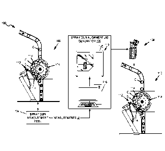
aligning a
spray gun 112 of a container spray machine 160, shown in FIG. 2.
101041 In this example, the spray machine 160 includes the
spray assembly 162 and
container transporter 164. The example spray assembly 162 includes a spray gun
112
mounted to an adjustable gun mount 166 (FIG. 3). The example container
transporter 164
includes a turret 170 with a container holder 114.
101051 As discussed with respect to FIG. 2, the operation 142
is performed to
determine a proper alignment of a spray gun 112. The alignment of the spray
gun 112 to
the container holder 114 and container C is important in order for the spray
gun 112 to
apply the coating to the container C in such a way that the coating has the
desired
characteristics. It is also important to avoid waste that may result from
overspraying.
101061 In typical applications there is not one proper
alignment for the spray gun.
Instead, there are many variables that require changes to the alignment. Some
of those
variables include the configuration of the spray gun, the configuration of the
nozzle, the
coating composition, the container configuration (size, shape, and material),
the intended
use of the container (intended contents, and characteristics of same), the
speed of rotation
of the spinner 172, the environment (temperature, humidity, altitude, etc.),
and many other
possible variables.
101071 In one example, a lab spray machine 102 is used to
determine a proper
alignment for the spray gun 112 using a particular set of these variables. For
example, a
particular type of container is selected to be coated with a particular
coating using a
16
CA 03154049 2022-4-7
WO 2022/006450
PCT/US2021/040175
particular spray gun with a particular spray nozzle under certain
environmental conditions.
Adjustments to the spray gun 112 alignment can then be made and tests can be
run by
spraying containers C with that particular set of variables. The coated
containers can then
be tested to determine whether the coating has certain characteristics,
including whether it
satisfies one or more predetermined criteria. Once the coating is determined
to satisfy the
predetermined criteria, the spray gun 112 can be determined to be in proper
alignment for
that particular set of variables.
[0108] Examples of predetermined criteria for the coating
include: an amount of a
surface that is coated, a thickness of the coating (including, e.g., an
average overall coating
thickness as well as coating thicknesses at different locations of the
container such as, e.g.,
upper sidewall, lower sidewall, etc.), an amount of surface that is exposed,
and an
electrical resistance of the coating or electrical current passage level of
the coating (e.g., to
indicate whether the coating is free of pores or other unsuitable coating
discontinuities). In
some embodiments the surface is an interior surface.
[0109] Once the spray gun 112 is properly aligned,
measurements can be taken to
measure the alignment of the spray gun 112.
[0110] The measurements are taken with respect to one or more
reference points. A
variety of possible reference points can be used. In this example the
alignment is defined
with reference to a central axis A and an origin point 0. The central axis A
is a central axis
of the container C, the container holder 114, and the axis of rotation of the
spinner 172.
The origin point 0 is a point along the central axis A on the surface of the
spinner 172.
But as noted, other reference points can be used in other embodiments.
[0111] One or more measurement tools are used to measure the
alignment of the spray
gun 112. Examples of measurement tools include rulers, calipers, laser
measurement tools,
protractors, scanners, and the like.
[0112] In some embodiments the alignment of the spray gun 112
includes both a
position and an orientation of the spray gun 112. An example position of spray
gun 112 is
illustrated in FIG. 5. The position is the location of a point of the spray
gun 112 relative to
the reference point. In this example, the location of the point of the spray
gun 112 is
measured in three-dimensions, including X, Y, Z coordinates where the
reference point is
the origin point 0. The dimension X represents the horizontal offset in a side-
to-side
(left/right) direction. X1 is a distance of the horizontal / side-to-side
offset from the central
axis A. The dimension Y represents the vertical offset in an up/down
direction. Y1 is a
distance of the vertical / up/clown offset from the central axis A. The
dimension Z
17
CA 03154049 2022-4-7
WO 2022/006450
PCT/US2021/040175
represents the horizontal offset in the forward/backward direction. Z1 is a
distance of the
horizontal / forward/backward position away from the origin point 0 along the
central axis
A.
[0113] FIG. 6 illustrates an example of the orientation of the
spray gun 112. The
orientation is the direction that the spray gun is pointing with respect to
the reference. The
direction of the spray gun 112 is along the spray axis SA. In this example,
the orientation
of the spray gun 112 is measured by three angles Pl, YA1, R1 with respect to
the central
axis A. The angle P1 is the pitch of the spray gun 112, and is an up/down
angle of the
spray axis SA with respect to the central axis A. The angle YA1 is the yaw of
the spray
axis SA, and is the horizontal side-to-side angle of the spray gun with
respect to the central
axis A. The angle R1 is the roll of the spray gun 112, and is an angle of
rotation of the
spray gun about the spray axis SA.
[0114] Each of the position and orientation can be measured
using measurement tools.
The measurements are then provided to the spray gun alignment jig generator
106 as
shown in FIG. 1, and as further described herein with reference to FIGS. 7-10.
[0115] FIG. 7 is a schematic block diagram illustrating an
example of the spray gun
alignment jig generator 106 for generating a spray gun alignment jig 108. In
this example,
the spray gun alignment jig generator 106 includes the computing device 116
and the jig
fabrication machine 118, such as a 3D printer 120. Some embodiments further
include an
alignment database 220 and a model elements database 222.
[0116] Once a proper alignment of the spray gun 112 has been
determined for a
particular coating and spray machine 160, the alignment measurements are
supplied to the
computing device 116. The computing device 116 uses the measurements to
generate a
digital model of an alignment jig 108 that is sized and configured for
positioning the spray
gun 112 into the proper alignment. An example of the computing device 116 is
illustrated
in FIG. 8. An example alignment jig generator interface 308 is illustrated in
FIG. 9. And,
an example of the generation of the digital model of the alignment jig 108 is
illustrated
and described in further detail herein with reference to FIGS. 11-19.
[0117] Once the digital model of the alignment jig has been
generated, it can be sent to
the jig fabrication machine 118 to be fabricated. The jig fabrication machine
118 generates
the physical alignment jig 108 from the digital model.
[0118] Some embodiments include an alignment database 220,
which can be part of
the spray gun alignment jig generator 106 (e.g., stored in computing device
116) or
separate from it but accessible to the computing device 116 across a data
communication
18
CA 03154049 2022-4-7
WO 2022/006450
PCT/US2021/040175
network. The alignment database 220 stores alignment measurements and other
data
Accordingly, in some embodiments the computing device 116 can receive the
alignment
measurements by retrieving the measurements from the alignment database 220.
An
example of the alignment database 220 is illustrated in FIG. 10.
[0119] Some embodiments include a model elements database 222,
which can
similarly be part of the spray gun alignment jig generator 106 or separate
from it but
accessible to the computing device 116 across a data communication network.
The model
elements database 222 stores digital models of model elements associated with
particular
spray machines 160, which can be utilized by the computing device 116 in
generating a
digital model of an alignment jig 108. An example of the model elements
database 222 is
illustrated in FIG. 13.
[0120] FIG. 8 illustrates an exemplary architecture of a
computing device that can be
used to implement aspects of the present disclosure, including any of the
computing
device 116 (FIGS. 1 and 7), the spray system controller 182 (FIG. 4), the
spray gun
controller 196 (FIG. 4), and the transport controller 200 (FIG. 4). The
computing device
illustrated in FIG. 8 can be used to execute the operating system, application
programs,
and software modules (including the software engines) described herein. By way
of
example, the computing device will be described below as the computing device
116. To
avoid undue repetition, this description of the computing device will not be
separately
repeated herein for each of the other computing devices, but such devices can
also be
configured as illustrated and described with reference to FIG. 8.
[0121] The computing device 116 includes, in some embodiments,
at least one
processing device 230, such as a central processing unit (CPU). A variety of
processing
devices are available from a variety of manufacturers, for example, Intel or
Advanced
Micro Devices ("AMD"). In this example, the computing device 116 also includes
a
system memory 232, and a system bus 234 that couples various system components
including the system memory 232 to the processing device 230. The system bus
234 is one
of any number of types of bus structures including a memory bus, or memory
controller; a
peripheral bus; and a local bus using any of a variety of bus architectures.
[0122] Examples of computing devices suitable for the
computing device 116 include
a server computer, a desktop computer, a laptop computer, a tablet computer, a
mobile
computing device (such as a smart phone, an iPod or iPad mobile digital
device, or
other mobile devices), or other devices configured to process digital
instructions.
19
CA 03154049 2022-4-7
WO 2022/006450
PCT/US2021/040175
101231 The system memory 232 includes read only memory 236 and
random access
memory 238. A basic input/output system 240 containing the basic routines that
act to
transfer information within computing device 116, such as during start up, is
typically
stored in the read only memory 236.
[0124] The computing device 116 also includes a secondary
storage device 242 in
some embodiments, such as a hard disk drive, for storing digital data. The
secondary
storage device 242 is connected to the system bus 234 by a secondary storage
interface
244. The secondary storage devices 242 and their associated computer readable
media
provide nonvolatile storage of computer readable instructions (including
application
programs and program modules), data structures, and other data for the
computing device
116.
[0125] Although the exemplary environment described herein
employs a hard disk
drive as a secondary storage device, other types of computer readable storage
media are
used in other embodiments. Examples of these other types of computer readable
storage
media include solid state memory, magnetic cassettes, flash memory cards,
digital video
disks, compact disc read only memories, digital versatile disk read only
memories, random
access memories, or read only memories. Some embodiments include non-
transitory
media. Additionally, such computer readable storage media can include local
storage or
cloud-based storage.
[0126] A number of program modules can be stored in secondary
storage device 242
or memory 232, including an operating system 246, one or more application
programs
248, other program modules 250 (such as the software engines described
herein), and
program data 252. The computing device 116 can utilize any suitable operating
system,
such as Microsoft WindowsTM, Google ChromeTm, Apple OS, and any other
operating
system suitable for a computing device.
101271 In some embodiments, a user provides inputs to the
computing device 116
through one or more input devices 254. Examples of input devices 254 include a
keyboard
256, mouse 258, microphone 260, and touch sensor 262 (such as a touchpad or
touch
sensitive display). Other embodiments include other input devices 254. The
input devices
are often connected to the processing device 230 through an input/output
interface 264 that
is coupled to the system bus 234. These input devices 254 can be connected by
any
number of input/output interfaces, such as a parallel port, serial port, game
port, or a
universal serial bus. Wireless communication between input devices and the
interface 264
is possible as well, and includes infrared, BLUETOOTH wireless technology,
IEEE
CA 03154049 2022-4-7
WO 2022/006450
PCT/US2021/040175
802.11, cellular, or other radio frequency communication systems in some
possible
embodiments.
[0128] In this example embodiment, a display device 266, such
as a monitor, liquid
crystal display device, projector, or touch sensitive display device, is also
connected to the
system bus 234 via an interface, such as a video adapter 268. In addition to
the display
device 266, the computing device 116 can include various other peripheral
devices (not
shown), such as speakers or a printer.
[0129] When used in a local area networking environment or a
wide area networking
environment (such as the Internet), the computing device 116 is typically
connected to the
network 272 through a network interface 270, such as an Ethernet interface.
Other possible
embodiments use other communication devices. For example, some embodiments of
the
computing device 116 include a modem for communicating across the network.
[0130] The computing device 116 typically includes at least
some form of computer
readable media. Computer readable media includes any available media that can
be
accessed by the computing device 116. By way of example, computer readable
media
include computer readable storage media and computer readable communication
media.
101311 Computer readable storage media includes volatile and
nonvolatile, removable
and non-removable media implemented in any device configured to store
information such
as computer readable instructions, data structures, program modules or other
data
Computer readable storage media includes, but is not limited to, random access
memory,
read only memory, electrically erasable programmable read only memory, flash
memory
or other memory technology, compact disc read only memory, digital versatile
disks or
other optical storage, magnetic cassettes, magnetic tape, magnetic disk
storage or other
magnetic storage devices, or any other medium that can be used to store the
desired
information and that can be accessed by the computing device 116. Computer
readable
storage media does not include computer readable communication media.
[0132] Computer readable communication media typically
embodies computer
readable instructions, data structures, program modules or other data in a
modulated data
signal such as a carrier wave or other transport mechanism and includes any
information
delivery media. The term "modulated data signal" refers to a signal that has
one or more of
its characteristics set or changed in such a manner as to encode infommtion in
the signal.
By way of example, computer readable communication media includes wired media
such
as a wired network or direct-wired connection, and wireless media such as
acoustic, radio
21
CA 03154049 2022-4-7
WO 2022/006450
PCT/US2021/040175
frequency, infrared, and other wireless media. Combinations of any of the
above are also
included within the scope of computer readable media.
101331 The computing device illustrated in FIG. 8 is also an
example of programmable
electronics, which may include one or more such computing devices, and when
multiple
computing devices are included, such computing devices can be coupled together
with a
suitable data communication network so as to collectively perform the various
functions,
methods, or operations disclosed herein.
101341 FIG. 9 is a schematic block diagram illustrating an
example alignment jig
generator interface 308, which can be used to collect alignment measurements
from an
operator. In this example, the alignment jig generator interface 308 includes
a spray
machine input region 310, a container input region 312, a coating input region
314, and an
alignment measurements input region 316. The example alignment measurements
input
region 316 includes a position section 318 and an orientation section 320.
Inputs fields
322, 323, 324, 326, 328, 330, 332, 334, and 336 are also shown.
101351 After measurements have been taken, in some embodiments
the measurements
are provided to the computing device 116 by the operator inputting the
measurements. As
one example, the measurements can be provided through an alignment jig
generator
interface 308 that is presented to the operator on the computing device 116
display device
266. Alternatively, the operator may access the interface 308 through another
computing
device, and the data is transmitted to the computing device 116, such as
through a network
272 (shown in FIG. 8). The data may be stored in the alignment database 220
shown in
FIG. 7.
101361 In this example, the interface 308 includes a spray
machine input region 310,
where the computing device 116 prompts the user to identify in the input field
322 the
spray machine for which measurements have been taken. In some embodiments the
computing device 116 retrieves from the alignment database a list of the spray
machines
which are in the database, and the user can select the spray machine from the
list, or a new
spray machine can be added. The input is provided into field 322. As discussed
in further
detail below, each spray machine can be associated with a set of data about
the spray
machine, and can also be associated with pre-configured model elements.
101371 The container input region 312 is similarly presented
to the operator to prompt
the operator to identify the container that was sprayed by the spray machine.
In some
embodiments the computing device 116 retrieves from the alignment database a
list of the
22
CA 03154049 2022-4-7
WO 2022/006450
PCT/US2021/040175
containers that are in the database, and the user can select the container
from the list, or a
new container can be added. The input is provided into field 323.
[0138] The coating input region 314 is similarly presented to
the operator to prompt
the operator to identify the coating that was sprayed by the spray machine. In
some
embodiments the computing device 116 retrieves from the alignment database a
list of the
coatings that are in the database, and the user can select the coating from
the list, or a new
coating can be added. The input is provided into field 324.
[0139] The alignment measurements input region 316 is also
presented to the operator
to prompt the operator to enter the measurements that were taken. In this
example, the
interface prompts the user to enter position measurements into the position
section 318 and
orientation measurements into the orientation section 320. The position
measurements for
the spray gun 112 are entered into the position section 318, and more
specifically the
offset, height, and distance measurements are entered into the respective
fields 326, 328,
and 330. The orientation measurements are entered into the orientation section
320, and
more specifically the pitch, yaw, and roll measurements are entered into the
respective
fields 332, 334, and 336.
[0140] FIG. 10 is a schematic block diagram illustrating an
example of the alignment
database 220. The alignment database 220 includes one or more data structures
that store
data including, for example, spray machine identifiers 352, coating
identifiers 354,
alignment measurements 356, and jig models 358.
[0141] After the measurements of the proper alignment of a
spray gun 112 have been
taken, and data entered such as through the alignment jig generator interface
308, shown
in FIG. 9, the data can be stored in data structures in the alignment database
220.
[0142] This example shows the data collected from the
operator, as discussed herein
with reference to FIG. 9, being stored in a first row of the alignment
database 220. More
specifically, the data includes a spray machine identifier 352 that identifies
sprayer 1, a
coating identifier 354 that identifies coating 1, and the alignment
measurements 356 that
identify both the position and the orientation of the alignment of the spray
gun.
[0143] Additionally, after a digital model of the alignment
jig 108 has been generated,
the digital model can also be stored in the alignment database 220. In this
example the
alignment database 220 includes a digital model of the alignment jig 108 as
model 1.
[0144] Additional measurement data can also be stored in the
alignment database 220,
as represented by the additional rows of data shown in FIG. 10
23
CA 03154049 2022-4-7
WO 2022/006450
PCT/US2021/040175
[0145] FIG. ills a flow chart illustrating an example method
370 of generating a
spray gun alignment jig 108 (shown in FIG. 7). The method 370 is an example of
the
operation 146, shown in FIG. 2. In this example the method 370 includes an
operation 372
and an operation 374.
[0146] The operation 372 is performed to generate a digital
model of the alignment jig
108. In some embodiments, the operation 372 is performed by the computing
device 116,
shown in FIGS. 7-8. An example of the operation 372 is illustrated and
described in more
detail with reference to FIGS_ 12-19.
[0147] The operation 374 is performed to fabricate the
alignment jig 108. The
operation 374 utilizes the digital model of the alignment jig 108 generated in
operation
372, and fabricates the physical alignment jig 108 that can subsequently be
used for
aligning the spray gun 112 with the container holder 114 and container C, as
previously
discussed. An example of the operation 374 is illustrated and described in
more detail with
reference to FIGS. 20-21.
[0148] FIG. 12 is a flow chart illustrating an example method
372 of generating a
digital model of the alignment jig 108. In this example the method 372
includes operations
380, 382, and 384_
[0149] The operation 380 is performed to generate a digital
model of a container
holder adapter. The container holder adapter is a portion of the alignment jig
108 that is
configured to engage with a container holder 114 of the spray machine 160. An
example
of the operation 380 is illustrated and described in more detail herein with
reference to
FIG. 14.
[0150] The operation 382 is performed to generate a digital
model of a spray gun
adapter. The spray gun adapter is a portion of the alignment jig 108 that is
configured to
engage with the spray gun 112 of the spray machine 160. An example of the
operation 382
is illustrated and described in more detail herein with reference to FIGS. 15-
16.
[0151] The operation 384 is performed to generate a digital
model of a linkage. The
linkage is a portion of the alignment jig 108 that is configured to connect
the spray gun
adapter and the container holder adapter in a predetermined alignment. An
example of the
operation 384 is illustrated and described in more detail herein with
reference to FIGS. 17-
19.
[0152] The operations of method 372 can be performed in any
order. For example, the
operation 382 that generates the digital model of the spray gun adapter can be
performed
before the operation 380 that generates the digital model of the container
holder adapter.
24
CA 03154049 2022-4-7
WO 2022/006450
PCT/US2021/040175
[0153] FIG. 13 is a schematic block diagram illustrating an
example of the model
elements database 222. The model elements database 222 includes one or more
data
structures that store data including, for example, spray machine identifiers
352, spray gun
adapter models 390, container holder adapter models 392, and interference data
394.
[0154] In some embodiments, certain component parts of the
alignment jig 108 can be
predefined for each spray machine_ For example, if sprayer I (shown in the
spray machine
identifier 352) is known to have a particular spray gun 112, a spray gun
adapter model 390
can be generated that has a particular configuration designed to interface
with that spray
gun. The spray gun adapter model 390 can then be stored in the database as
represented by
gun adapter 1, shown in FIG. 13. Similarly, other spray gun adapter models 390
can be
generated for spray guns of other spray machines, and stored in the database
222.
[0155] The spray machine may also have a particular known
configuration of its
container holder adapter, and a container holder adapter model 392 can be
generated that
has a particular configuration designed to interface with that container
holder. The
container holder adapter model 392 can then be stored in a database 222 as
represented by
holder adapter 1, shown in FIG. 13. Similarly, other container holder adapter
models 392
can be generated for container holders of other spray machines, and stored in
the database
222.
[0156] In some embodiments, model elements database 222 also
includes interference
data 394. The interference data 394 is associated with a particular spray
machine 160 by
the spray machine identifier 352, such as sprayer 1, and identifies the
location of any
portion of the spray machine within the vicinity of the spray gun 112 and
container holder
114 that may interfere with the alignment jig 108. One example of the
interference data
394 is a three-dimensional model of at least a portion of the spray machine.
In this way,
the computing device 116 can use the interference data 394 to design the
alignment jig 108
so that it does not interfere with any portion of the spray machine. An
example process
that utilizes the interference data 394 to design the alignment jig 108 is
described in
further detail with reference to FIG. 19.
[0157] FIGS. 14-19 illustrate examples of the method 372 of
generating a digital
model of the alignment jig 108, and its operations 380, 382, and 384 of FIG
12, which
may be performed by the computing device 116 of the spray gun alignment jig
generator
106. In some embodiments, the computing device 116 provides a model space 400
in
which the digital model of the alignment jig 108 is designed. The model space
400 is a
working environment of a computer program, such as a computer aided design
(CAD)
CA 03154049 2022-4-7
WO 2022/006450
PCT/US2021/040175
software application (which includes various available 3D modelling software
applications). A wide variety of CAD software applications are available and
can be
utilized. Several examples include Autodesk AutoCAD , Dassault Systemes
Solidworks , and Autodesk , Fusion 3600 TM. The model space 400 can be
displayed on a
display device 266 of the computing device 116, or can be executed within the
computing
device 116 without being displayed.
101581 The operations of method 372 can be fully automated by
the computing device
116, or can be performed in cooperation with a human operator (i.e., partially
automated
and partially manual). The computer aided design software application includes
software
engines and algorithms implemented as tools, functions, or macros, for
example, to
perform the operations described herein.
[0159] It should be appreciated that the configuration of the
digital model of the
various components described herein is the same or very similar to the
configuration of the
actual physical components fabricated from the digital model. Accordingly, the
same
names and reference numbers will be used for like components regardless of
whether such
components are in the digital model or the physical component fabricated from
the digital
model.
[0160] FIG. 14 is a schematic diagram illustrating an example
digital model 402 of a
container holder adapter 404. The digital model 402 is shown in the model
space 400 of
the computing device 116 shown in FIG. 7. In this example, the container
holder adapter
404 includes a body 406 including a container portion 408 and an orientation
guide 410
(such as including 410a and 410b). Also shown are a first end 412, a second
and 414, and
a container reference point 416. FIG. 14 also illustrates an example of the
operation 380
shown in FIG. 12.
[0161] The container holder adapter 404 is a portion of the
alignment jig 108 that is
configured to engage with the container holder 114 of the spray machine 160
(FIG. 3).. As
such, the container holder adapter 404 is designed so that it will fit in a
container holder
114 of the spray machine 160.
[0162] In some embodiments, an operator is prompted to select
from a user interface
an identification of the spray machine for which the alignment jig 108 is to
be designed.
The operator selects the spray machine, such as sprayer 1, as shown in FIG.
13. The
computing device 116 then retrieves the digital model 402 of the container
holder adapter
404 from the model elements database 222, based on the identification of the
spray
machine selected by the operator. If a digital model 402 of the container
holder adapter
26
CA 03154049 2022-4-7
WO 2022/006450
PCT/US2021/040175
404 does not exist for the selected spray machine, a new model can be
generated based on
the configuration of the container holder 114, such as using the interference
data 394 (FIG.
13).
[0163] The body 406 includes a container portion 408 that has
a size and shape that
mimics the container C, so that it can be inserted within and held by the
container holder
114 in the same way that the container holder 114 holds a container while it
is being
sprayed. If the spray machine 160 is configured to spray a cylindrical food
can, for
example, the container portion 408 is sized and shaped to mimic the
cylindrical size and
shape of the food can. In this example, the container portion 408 has a length
Li and a
diameter DI. The length Li (from a first end 412 to a second end 414) is
selected to be the
same or similar length as the container C, and the diameter D1 is selected to
be the same
or similar diameter as the container C. The size and shape of the container
can be
determined by the computing device 116 by retrieving the information from the
alignment
database 220 for the container identified in field 323 (FIG. 9). The container
portion 408
can have other shapes and sizes in other embodiments.
[0164] The container portion 408 is designed with reference to
a particular container
reference point 416. In this example, the container reference point 416
represents the same
reference point 0 from which the spray gun alignment measurements were taken,
as
discussed herein with reference to FIGS. 5 and 6. Accordingly, the shape of
the container
portion 408 is designed so that a central axis is aligned with the container
reference point
416 and the length Li is measured as a distance from the container reference
point 416.
[0165] The container portion 408 has a size that is the same
or similar to that of the
container C that is to be sprayed. Examples of containers C can include both
food arid
beverage cans, as well as other cans such as metered dose inhaler cans (e.g.,
for dispensing
of pharmaceutical products such as asthma inhalants), aluminum monobloc cans
(e.g., for
pressurized hair-dyes, cleaning products, air freshener, and the like), etc.
[0166] Some standard can sizes, which are examples of suitable
containers C, are
shown in Table 1.
27
CA 03154049 2022-4-7
WO 2022/006450
PCT/US2021/040175
[0167] TABLE 1
Can Type Dimensions (diameter Capacity
Di x height L I) (US. fluid ounces)
6Z 22/16x 314 inches 6,08
(5.4 cm x 8.89 cm) (179.81 ml)
8Z Short 2i1A6 x 3 inches 7.93
(6.83 cm x 7.62 cm) (234_52 ml)
8Z Tall 211ii6 x 324 inches 8.68
(6.83 cm x 8.26 cm) (256.70 ml)
No. I (Picnic) 211/16 X 4 inches 10.94
(6.83 cmx 10_16 cm) (323_53 ml)
No. 211 Cylinder 211/16 x 414/16 inches 13.56
(6,83 cm x 12.38 cm) (401.02 ml)
No. 300 3 x 47/16 inches 15.22
7.62 cm x 11_27 cm) (450_11 ml)
No. 300 Cylinder 3 x 59/16. inches 19.40
(7,62 cm x 14.13 cm) (573.73 ml)
No. I Tall 31/46x 41 A6 inches 16.70
(7,78 cm x 11,91 cm) (493.88 ml)
No. 303 3-3A6x 4% inches 16.88
(8,1 cm x 11,11 cm) (499.20 ml)
No. 303 Cylinder 3%6x 59/16 inches 21.86
(8.1 cm x 14.13 cm) (646.47 ml)
No. 2 Vacuum 37/16x 3% inches 14.71
(8.73 cm x 8.57 (.µ,trt) (435.03 ml)
No. 2 37A6 x 49/16 inches 20.55
(8.73 cm x 11_59 cm) (607.74 ml)
Jumbo 37/16x 5% inches 25,80
(8.73 cm x 14_29 cm) (763_00 ml)
28
CA 03154049 2022-4-7
WO 20221006450
PCT/US2021/040175
No. 2 Cylinder 37/16x 5% inches 26.40
(8,73 cm x 14.61 cm) (730.71
No. 1.25 41/16x 23/s inches 13.81
(10,32 cm x 6,03 cm) (408,11 ml)
No. 2.5 41/16x 411/16 inches 29.79
(10.32 cm x 11.91 cm) (831.00 ml)
No. 3 Vacuum 414 x 37,46 inches 23.90
(10.8 cm x 8.73 cm) (706.81 ml)
No. 3 Cylinder 414 x 7 inches 51.70
(10.8 cm x 17.78 cm) (1528.95 ml)
No. 5 51/8 x 55/i inches 59.10
(13.02 cm x 14.29 cm) (1747.80 nil)
No. 10 63/16x 7 inches 109.43
(15.72 cm x 17.78 cm.) (3236.23 ml)
21Ix300 7.90
211/16 x 3 inches (233.63 ml)
(6.83 cm x 7.62 cm)
307x.512 25.8
37/16x 512/16 inches (763.00 ml)
(8,73 cm x 14,61 cm)
101681 In one example, the length Li is in a range from 1 to
24 inches (2.54 cm to
60.96 centimeters). In another example, the length Li is in a range from I to
12 inches
(2.54 to 30.48 centimeters). In yet another example, the length Li is in a
range from 3 to 7
inches (7.62 to 17,78 cm). The length Li can also be referred to as a height
Li.
[0169] In one example, the diameter Di is in a range from 1 to
18 inches (2.54 to
45.72 centimeters). In another example, the diameter Dlis in a range from 2 to
12 inches
(5.08 to 30.48 centimeters). In yet another example, the diameter Di is in a
range from 2.5
to 7 inches (635 to 17.78 centimeters).
29
CA 03154049 2022-4-7
WO 2022/006450
PCT/US2021/040175
101701 In some embodiments the container C is a D&I (drawn and
ironed) food can. In
one example, the diameter D1 of the D&I can is in a range from 2 inches (50.8
min) to 6
inches (152.4 mm). In another example, the diameter D1 of the D&I can is in a
range from
2 and 11/16 inches (68.26 mm) to 3 and 7/16 inches (87.31 mm).
17 1] In one example, the length (height) Li of the D&I can is
in a range from 1 inch
(25.4 mm) to 8 inches (203.2 mm). In another example, the length (height) L1
of the D&I
can is in a range from 3 inches (76.2 mm) to 5 and 12/16 inches (146.05 mm).
101721 In some embodiments the dimensions described herein are
maximum
dimensions. For example, some containers C have various dimensions due to the
presence
of features such as a neck or ribs, which can cause some portions of the
container C to
have a narrower diameter than others portions.
101731 In some embodiments, the body 406 also includes an
orientation guide 410.
The orientation guide 410 provides one or more additional features to the body
406 to
ensure that the container holder adapter 404 is inserted into the container
holder 114 in the
proper orientation. For example, when the container portion 408 has a
cylindrical shape it
could be rotated and inserted into the container holder 114 in a variety of
different
positions_ Therefore, the orientation guide 410 is provided so that the body
406 can only
be inserted one way into the container holder 114.
101741 The particular configuration of the orientation guide
410 is selected based on
the configuration of the spray machine 160. For an example spray machine 160
shown in
FIG. 3, the container holder 114 is at least partially defined by a turret
170. The turret 170
has edge features adjacent to the container holder 114. In this example, the
orientation
guide 410 includes orientation fins 410a and 410b that extend outward from the
container
portion 408 and the adjacent to the edge features of the turret 170 when the
container
holder adapter 404 is inserted into the container holder 114. Other
orientation guide 410
features can be used in other embodiments depending on the particular
configuration of
the spray machine 160.
101751 FIGS. 15 and 16 are schematic diagrams illustrating an
example digital model
430 of a spray gun adapter 432. The digital model 430 is shown in the model
space 400 of
the computing device 116, shown in FIG. 7. FIG. 15 shows a rear perspective
view of the
digital model 430 of the spray gun adapter 432, and FIG. 16 shows a side
perspective
view. An example spray gun 112 is also shown in broken lines in FIG. 16 for
reference.
FIGS. 15 and 16 are also examples of the operation 382 shown in FIG. 12.
CA 03154049 2022-4-7
WO 2022/006450
PCT/US2021/040175
[0176] In this example, the spray gun adapter 432 includes a
body 434 including a
base 436, a spray gun fastener 438, and a tool port 440. The spray gun
fastener 438
includes fastening arms 442a and 442b in this example. The base 436 also
includes a tip
alignment receptacle 444 including a tip reference point 446 (shown in FIG.
16).
[0177] The spray gun adapter 432 is a portion of the alignment
jig 108 and is
configured to engage with the spray gun 112 of the spray machine 160 (FIG. 3).
The spray
gun adapter 432 is designed to fasten onto the spray gun 112.
[0178] In some embodiments, after an operator has identified
the spray machine for
which the alignment jig 108 is to be designed, the computing device 116
retrieves a digital
model 430 of the spray gun adapter 432 from a model elements database 222. If
a digital
model 430 of the spray gun adapter 432 does not exist for the selected spray
machine, a
new model can be generated based on the configuration of the spray gun 112,
such as
using the interference data 394 (FIG. 13).
[0179] The body 434 includes a base 436 that has a size and
shape similar to the
second end 414 of the container portion of the container holder adapter 404,
shown in FIG.
14.
[0180] The body 434 also includes a spray gun fastener 438
that is sized and shaped to
engage with and fasten onto the spray gun 112. Accordingly, the particular
configuration
of the spray gun fastener 438 is designed based on the configuration of the
spray gun 112.
In this example, the spray gun fastener 438 includes a pair of spaced apart
fastening arms
442a and 442b. The surfaces between the two fastening arms 442a are flat, and
are spaced
apart a precise distance to securely engage with corresponding surfaces of the
spray gun
112. A rear surface at the intersection between the fastening arms 442a and
442b provides
a backstop that engages with another corresponding surface of the spray gun
112.
[0181] The tool port 440 is a cutaway section of the body 434
arranged between the
base 436 and the spray gun fastener 438. The tool port 440 provides a
receptacle into
which a tool can be inserted to interact with and adjust the spray gun 112,
such as to rotate
the nozzle to an appropriate orientation.
[0182] The base 436 also includes the tip alignment receptacle
444 and tip reference
point 446, as shown in FIG. 16. The tip alignment receptacle 444 is configured
to receive
the tip 113 of the spray gun 112 to align the spray gun adapter 432 with the
tip 113 of the
spray gun 112. More particularly, the tip alignment receptacle 444 includes
the tip
reference point 446. The spray gun adapter 432 and tip alignment receptacle
444 are
configured so that the tip 113 of the spray gun 112 fits precisely into the
tip reference
31
CA 03154049 2022-4-7
WO 2022/006450
PCT/US2021/040175
point 446. In some embodiments the tip alignment receptacle 444 is also shaped
so that the
tip 113 only fits into it if it is properly aligned.
101831 FIG. 17 is a schematic diagram illustrating the
alignment of the digital model
402 of the container holder adapter 404 with the digital model 430 of the
spray gun
adapter 432 in the model space 400. In this example, the container holder
adapter 404
includes the container reference point 416, and the spray gun adapter 432
includes the tip
reference point 446.
[0184] Once the container holder adapter 404 and the spray gun
adapter 432 have been
generated by the computing device 116, they are then arranged within the model
space 400
to be aligned with one another. Because the container holder adapter 404 and
spray gun
adapter 432 each have reference points 416 and 446 that correspond with the
same
reference points from which the spray gun alignment measurements were
previously
taken, the same alignment measurements 356 (FIG. 10) can be retrieved from the
alignment database 220 and used for alignment of the container holder adapter
404 with
the spray gun adapter 432. In the example shown in FIG. 10, the alignment
measurements
for Sprayer 1 with Coating 1 include a position offset of X1 cm, height of Y1
cm, and
distance of Z1, and (not labeled in FIG. 17) an orientation pitch of P1, yaw
of YA1, and
roll of R1 .
[0185] For example, the spray gun adapter 432 is arranged so
that its tip reference
point 446 is offset from the container reference point 416 of the container
holder adapter
404 by X1 cm, has a height of Y1 cm, and has a distance of Z1 cm.
[0186] Similarly, the spray gun adapter 432 is arranged so
that its orientation has a
pitch P1, yaw YA1, and roll R1 (not labeled in FIG. 17).
[0187] FIG. 18 is a schematic diagram illustrating the
generation of a digital model
460 of the linkage 462 in the model space 400. FIG. 18 shows the digital model
402 of the
container holder adapter 404 and the digital model 430 of the spray gun
adapter 432. A
surface of the linkage 462 is shown defined by connecting lines 464. FIG. 18
is also an
example of the operation 384 shown in FIG. 12.
[0188] Once the container holder adapter 404 and spray gun
adapter 432 have been
properly aligned as illustrated and described with reference to FIG. 17, the
linkage is then
generated to connect the spray gun adapter 432 and the container holder
adapter 404 in
that predetermined alignment.
101891 In some embodiments, the linkage 462 is generated by
connecting a rear
surface of the base 436 of the spray gun adapter 436 to the second end 414 of
the container
32
CA 03154049 2022-4-7
WO 2022/006450
PCT/US2021/040175
holder adapter 404. For example, perimeters of each surface are connected by
defining a
surface extending between the two perimeters, as illustrated by the connecting
lines 464.
The area inside of the connecting lines 464 and between the spray gun adapter
436 and the
container holder adapter 404 can then be filled to generate the linkage 462.
[0190] In some embodiments the linkage 462 that has been
generated is then analyzed
using the interference data 394 from the model elements database 222. The
interference
data is used to check the area of the linkage 462 to determine whether it
would interfere
with any portion of the spray machine 160. If an interference is identified,
then the digital
model 460 of the linkage 462 is modified to eliminate the interference, such
as by adding a
notch, cutout, recess, or the like at the location of the interference.
[0191] The linkage 462 can be formed so that it is directly
connected to and joins
together the spray gun adapter 432 and the container holder adapter 404, such
that the
spray gun alignment jig 108 is one unitary piece. In other embodiments, the
spray gun
alignment jig 108 can be formed of multiple pieces, such as shown in FIG. 18.
[0192] FIG. 19 is a schematic diagram further illustrating the
generation of the digital
model 460 of the linkage 462 in the model space 400. In this example, the
linkage 462
includes a releasable joint 470. In this example, the releasable joint 470
divides the spray
gun alignment jig 108 into two pieces, and includes keyed features 472 and
474.
[0193] In some embodiments it is advantageous for the spray
gun alignment jig 108 to
be formed of two or more pieces. For example, a two-piece design allows the
container
holder adapter 404 to be inserted into the container holder 114 (FIG. 3) and
the spray gun
adapter 432 to be separately fastened to the spray gun 112. Then, the two
parts can be
brought together using the adjustable gun mount 166 (FIG. 3) and aligned while
connecting the pieces at the releasable joint 470. Similarly, in some
embodiments the
releasable joint 470 makes it easier to remove the spray gun alignment jig 108
from the
spray machine 160.
[0194] In some embodiments the releasable joint 470 includes
keyed features 472 and
474. The feature 472 is a male feature arranged at one surface of the
releasable joint 470,
and the feature 474 is a female feature arranged in the other surface. The
features are
configured with corresponding shapes so that they can only fit together in one
direction. In
this way the alignment of the spray gun adapter 432 with the container holder
adapter 404
is preserved.
101951 Once the generation of the spray gun alignment jig 108
is completed, the
digital model 450 can be saved in a computer-readable storage device. In some
33
CA 03154049 2022-4-7
WO 2022/006450
PCT/US2021/040175
embodiments the digital model 450 is stored in a 3D CAD file format In another
possible
embodiment, the digital model 450 is stored in a stereolithography (STL) file
format
particularly suited for transmitting the digital model 450 to the jig
fabrication machine
118. The digital model 450 may also be stored in both or multiple file
formats. In some
embodiments the digital model 450 is stored as a jig model 358 in the
alignment database
220 (FIG. 10).
[0196] FIG. 20 is a front view of an example jig fabrication
machine 118, and more
specifically an example of a 3D printer 120 for printing the spray gun
alignment jig 108.
[0197] After the spray gun alignment jig has been generated by
the computing device
116, it can then be transmitted to the jig fabrication machine 118 to be
fabricated. For
example, the digital model 450 (FIG. 19) can be transmitted to the 3D printer
120.
[0198] To improve the efficiency of printing, a plurality of
the spray gun alignment
jigs 108 (of the same or different configurations) can be printed
simultaneously.
[0199] A variety ofjig fabrication machines 118 can be used,
such as those previously
discussed herein. Additionally, a wide variety of 3D printers are available,
which can
generate the spray gun alignment jig 108 using a variety of different
materials. One
example of a 313 printer is the FuSion3TM 3D printer, which can utilize
printing filaments
comprised of various different materials including Polyethylene Terephthalate
Glycol-
Modified (PETG), Polylactic Acid (PLA), and Acrylonitrile Butadiene Styrene
(ABS).
[0200] FIG. 21 is a perspective view of an example of the
physical spray gun
alignment jig 108. Examples of the spray gun alignment jig 108 are described
in detail
herein with reference to the digital models 450 (including digital models 402,
430, and
460) in FIGS. 14-19.
[0201] FIG. 22 is a flow chart illustrating an example method
148 of aligning a spray
gun 112 using a spray gun alignment jig 108. In this example, the method 148
includes
operations 492, 494, and 496.
[0202] The operation 492 is performed to insert a container
holder adapter 404 into the
container holder 114. An example of the operation 492 is illustrated in FIG.
23.
[0203] The operation 494 is performed to fasten the spray gun
adapter 432 to the spray
gun 112. An example of the operation 494 is illustrated in FIG. 24.
[0204] The operation 496 is performed to connect the spray gun
adapter 432 to the
container holder adapter 404 to align the spray gun 112 with the container
holder 114 and
the container C. In some embodiments, connecting the spray gun adapter 432 to
the
container holder adapter 404 involves fastening the releasable joint of the
linkage 462, as
34
CA 03154049 2022-4-7
WO 2022/006450
PCT/US2021/040175
illustrated and described with reference to FIG. 19. An example of the
operation 496 is
illustrated in FIG. 25.
[0205] FIG. 23 is a perspective view illustrating a portion of
an example container
transporter 164 of a spray machine 160, and further illustrating the container
holder
adapter 404 portion of the spray gun alignment jig 108. In this example, the
container
transporter 164 includes the turret 170, the container holder 114, and the
spinner 172.
[0206] The container holder adapter 404 portion of the spray
gun alignment jig 108 is
inserted into the container holder 114 at a position where a container C is to
be sprayed by
the spray gun 112. The container holder adapter 404 is positioned so that it
is in the
container holder 114, the first end of the container holder adapter 404 is
against the
spinner 172, and the orientation guides 410 are against the edges of the
turret 170.
[0207] FIG. 24 is a perspective view illustrating a portion of
an example spray gun
112, and further illustrating the spray gun adapter 432 portion of the spray
gun alignment
jig 108. In this example, the spray gun adapter 432 includes the spray gun
fastener 438
including the fastening arms 442a and 442b, the tip alignment receptacle 444,
and the tip
reference point 446. The spray gun 112 includes the tip 113 and alignment
surfaces 502.
[0208] The spray gun adapter 432 portion of the spray gun
alignment jig 108 is
fastened onto the spray gun 112. The inwardly facing surfaces of the fastening
arms 442a
and 442b are secured to the alignment surfaces 502, and the tip 113 is
inserted into the tip
alignment receptacle 444, such that the tip 113 is positioned at the tip
reference point 446_
[0209] FIG. 25 is a perspective view of the spray gun
alignment jig 108 being used to
align the spray gun 112 with the container holder 114 of the container spray
machine 160.
[0210] With the container holder adapter 404 inserted into the
container holder 114
and the spray gun adapter 432 is fastened to the spray gun 112, the adjustable
gun mount
166 (FIG. 3) is adjusted to move the spray gun 112 and spray gun adapter 432
toward each
other. The spray gun adapter 432 and container holder adapter 404 portions are
then joined
together using the releasable joint. Once connected, the spray gun 112 is
properly aligned
with the container holder adapter 404 and the alignment can be locked in place
using the
adjustable gun mount 166. The spray gun alignment jig 108 is then removed from
the
spray machine, and the spray machine is ready for use.
102111 The two-part configuration of the spray gun alignment
jig 108 makes it easier
to remove the spray gun alignment jig 108 from the spray machine 160. For
example, the
container holder adapter 432 can first be separated from the spray gun adapter
432 at the
releasable joint 470 while the parts are still coupled to the respective
container holder 114
CA 03154049 2022-4-7
WO 2022/006450
PCT/US2021/040175
and spray gun 112. The container holder adapter 432 can then be removed from
the
container holder 114, and the spray gun adapter 432 can then be removed from
the spray
gun 112.
[0212] The spray machine 160 has an adjustable gun mount 166
(FIG. 3) that allows
the precise position of the spray gun 112 to be locked in place and properly
aligned using
the spray gun alignment jig 108, but also includes a pivotable joint that
allows the spray
gun 112 to be pivoted away from the container holder 114 into an open position
that
allows the operator to access both the spray gun 112 and the container holder
114. The
pivotable joint can then be returned to and locked into place in an operating
position such
that the precise alignment of the spray gun 112 with respect to the container
holder 114 is
preserved.
[0213] In some embodiments, the spray gun alignment system 100
described herein
ensures standardization of spray setup. The spray gun alignment can be easily
accomplished by spray machine operators, and requires less training and
practice.
[0214] The spray gun alignment system 100 provides repeatable
spray setups across
every spray machine regardless of operator, and reduces the chance for errors
to be made.
It also minimizes downtime due to coating changeovers, and significantly
reduces spoilage
and overspray due to poor spray setup.
[0215] Although the present disclosure makes use of several
specific examples of
containers that can be coated by the spray machine 160, the system 100 is not
limited to
applying coatings to only these examples. A wide variety of articles may be
sprayed using
the system 100. Articles may be made of a variety of materials including metal
or glass.
Examples of such articles include beer or soda bottles, wine bottles, liquor
bottles,
pharmaceutical containers, cosmetic containers, aerosol cans, paint
containers, perfume
containers, candle holders, dishware (e.g., plates, stemware, mugs, etc.),
vases, glass tile,
glass mosaics, shaped components for mirror application, window glass, and
molded
components for various applications (e.g., automotive, aviation, etc.). Some
articles may
also be exterior coated for aesthetic purposes.
[0216] The spray gun alignment system 100 can be manufactured
for use with any
spray gun setup and any spray coating. Suitable spray coating chemistries may
include, for
example, sprayable water-borne coating compositions (which may include some
organic
solvent), sprayable organic-solvent-based coating compositions (which may
include a de
minimus amount of water such as, e.g., 2 weight percent ("wt-%") or less, if
any), and
sprayable powder coating compositions. The coatings may include any suitable
36
CA 03154049 2022-4-7
89999793
combination of one or more film-forming components and other coaling
adjuvants. Such
film-forming components may include, for example, latex emulsions, organic
solution
polymerized acrylic polymers, polyester polymers, polyether polymers,
polyether-acrylate
polymers, polyester-acrylate polymers, polyolefin polymers, and copolymers and
combinations thereof.
102171 In some embodiments, the spray gun alignment system 100 (and the
spray gun
alignment jig 108) may be adapted to facilitate interior spray coating of food
or beverage
cans, or other packaging containers, using any one of the following inside
spray products:
the INNOVEL HPSTm series of water-borne acrylic beverage can inside spray
products from PPG, which is described in manufacturer literature as having a
solids
contents of 201 1 wt-% (15 minutes at 200 C), a viscosity of about 201 2
seconds (Ford
number 4 cup at 25 C), and a density of 1,02 1 (20 C);
the INNOVEL MAXTM internal spray lacquer products from PPG for aluminum
aerosol cans;
the INNOVEL VCLTM clear internal spray product from PPG for aluminum bottles,
aerosols and tubes;
the NUTRISHEILD SOLISTATm non-BPA internal spray products from PPG for
D&I (drawn and ironed) food cans;
the PPG6100TM and PPG 6150TM internal gold and aluminized spray coating
products from PPG for D&I food cans;
the AQUALURE G1 5OTM beverage can inside spray product from Alczo-Nobel,
which is described by manufacturer literature as a water-borne modified
acrylic BPA-NI
(bisphenol A non-intent) coating composition typically having the following
properties
18-19% solids, target applied film weight of (330 ml beverage can) 3 grams per
square
meter or "gsm" (typically 110 mg per can), total volatile organic content
("VOC") of
about 14.2 wt-% (19 wt-% nvm valiant), and a viscosity of 32-47 seconds (ISO 4
Cup at
25 C);
the acrylic and polyether-acrylic beverage can inside spray products sold
under the
VALPURETM line of non-BPA products by The Sherwin-Williams Company;
the polyether-acrylic and polyester two-piece D&I food can inside spray
products
sold under the VALPURETM line of non-BPA products by The Sherwin-Williams
Company;
the CANV'ERA I110TM beverage can inside spray product from Dow, which is
described in manufacturer literature as an aqueous acid-modified polyolefin
dispersion
37
Date Recue/Date Received 2022-11-11
89999793
that can be formulated into a sprayable coating composition having 20 1 wt-%
solids and
a viscosity of 18-40 seconds (Ford number 4 cup at 21 C); and
the CANVERA 3110Tm food can internal spray product from Dow, which is
described in manufacturer literature as an aqueous acid-modified polyolefin
dispersion
that be formulated into a sprayable coating composition having 18% to 40%
solids (e.g., a
coating composition having about 31% solids and viscosity of 23 2 seconds
(Ford
number 4 cup at 21 C).
102181 In some embodiments the spray gun alignment jig 108 includes
indicia that
correlates it to a particular spray coating. For example, when a spray gun
alignment jig
108 is configured to align the spray machine 160 for spraying a particular
spray coating,
the spray gun alignment jig 108 includes indicia that can be used to identify
the particular
spray coating. Examples of the coatings are described in the list above and
throughout this
specification. One example of a suitable indicia is a name of the spray
coating (which can
be printed on, engraved into, or otherwise formed on a surface of the spray
gun alignment
jig 108, or printed onto a label that is then applied to the surface of the
spray gun
alignment jig 108). Other examples of indicia include a human-readable code or
a
machine-readable code (e.g., barcode or QR code) associated with the spray
coating_
Another example of a suitable indicia is a color of the spray gun alignment
jig 108, or a
portion thereof. For example, the spray gun alignment jig 108 can be made with
a material
having a selected color, and the color is associated with the spray coating.
[0219] The various embodiments described above are provided by way of
illusti .. ation
only and should not be construed to limit the claims attached hereto_ Those
skilled in the
art will readily recognize various modifications and changes that may be made
without
following the example embodiments and applications illustrated and described
herein, and
without departing from the true spirit and scope of the following claims.
38
Date Recue/Date Received 2022-11-11