Note: Descriptions are shown in the official language in which they were submitted.
I
System and method for the production of synthetic
fuels without fresh water
5 The present invention relates to a system and to a method for producing
synthetic
fuels, in particular jet fuel, diesel and/or gasoline.
There are a number of different methods for producing fuels, such as jet fuel,
diesel,
gasoline or the like. Such methods are mainly based on the processing of
fossil raw
10 materials, such as the refining of crude oil, the liquefaction of coal
or the synthesis of
fuels from natural gas, water and oxygen. The synthesis of fuels from natural
gas,
water and oxygen is also known as the "gas-to-liquids" method. In this method,
syn-
thesis gas comprising hydrogen and carbon monoxide is first produced from
natural
gas, water and oxygen, which is then converted to hydrocarbons in a Fischer-
Trop-
15 sch synthesis, which hydrocarbons consist primarily of long-chain normal
paraffins.
These hydrocarbons are then converted into synthetic fuels by means of
cracking
and isomerization.
A similar method is the conversion of electrical energy into synthetic fuels,
which is
20 known as "power-to-liquids." For this purpose, water and carbon dioxide
are con-
verted into synthesis gas, which is then processed into synthetic fuels in a
similar
way to the "gas-to-liquids" method. A significant disadvantage of the "gas-to-
liquids"
method and the "power-to-liquids" method is that considerable amounts of fresh
wa-
ter are required. However, water of the required purity is an expensive raw
material.
25 In addition, in the known methods, comparatively large quantities of
waste gases and
waste water that are unused in the methods are produced that are undesirable
from
an environmental point of view.
Proceeding from this, the object of the present invention was to provide a
system
30 and a method for producing synthetic fuels, which can be operated
without or with at
most a small amount of fresh water supply and with the production of only very
small
amounts of unused exhaust gases and waste water, which results in an increased
CA 03155106 2022-4-14
2
yield of synthetic fuels, and which can still be operated exclusively with
electrical en-
ergy and preferably renewable energy.
According to the invention, this object is achieved by a system for producing
syn-
5 thetic fuels, in particular jet fuel, diesel and/or gasoline, which
comprises:
a) an apparatus for separately extracting carbon dioxide and water from
ambient
air,
b) a synthesis gas production apparatus for producing a raw synthesis gas
com-
prising carbon monoxide, hydrogen, carbon dioxide and water, the synthesis
10 gas production apparatus having a supply line for carbon dioxide
leading from
the apparatus for separately extracting carbon dioxide and water from ambient
air, a supply line for air and a supply line for water or water vapor,
c) a separating apparatus for separating carbon dioxide and water from the
raw
synthesis gas produced in the synthesis gas production apparatus,
15 d) a Fischer-Tropsch apparatus for producing hydrocarbons by means of
a
Fischer-Tropsch process from the synthesis gas from which carbon dioxide
and water were separated in the separating apparatus,
e) a refining apparatus for refining the hydrocarbons
produced in the Fischer-
Tropsch apparatus into synthetic fuels,
20 f) a desalination apparatus for desalinating water, the desalination
apparatus
having a water supply line from the apparatus for separately extracting carbon
dioxide and water from ambient air and a water discharge line to the Fischer-
Tropsch apparatus, and
g) a water purification apparatus comprising a water
supply line leading from the
25 Fischer-Tropsch apparatus for purifying water produced therein,
the system further comprising a pre-reformer for converting hydrocarbons other
than
methane into methane, carbon oxides, water and hydrogen and i) a water vapor
sup-
ply line leading from the water purification apparatus to the pre-reformer,
ii) a pro-
cess gas supply line leading from the refining apparatus to the pre-reformer
and/or a
30 return gas line leading from the Fischer-Tropsch apparatus to the pre-
reformer and
iii) a circulation line leading from the pre-reformer to the supply line for
water or water
vapor connected to the synthesis gas production apparatus.
CA 03155106 2022-4-14
3
In that in the system according to the invention and the method according to
the in-
vention the water required for fuel synthesis, in particular for synthesis gas
produc-
tion and for Fischer-Tropsch synthesis, is partly obtained from ambient air
and the
5 carbon dioxide required for this is completely obtained from ambient air
and the (re-
action) water produced during fuel synthesis, such as in particular Fischer-
Tropsch
synthesis, in the water purification apparatus and preferably also the
(reaction) water
produced in synthesis gas production in the desalination apparatus are
purified to
the extent required for circulation, processed in the pre-reformer and
returned from
10 there to the synthesis gas production apparatus, the system according to
the inven-
tion and the method according to the invention can be operated solely with the
water
produced from ambient air and (reaction) water produced from the operation of
the
system in Fischer-Tropsch synthesis and optionally other system parts, such as
the
synthesis gas production apparatus, i.e., without or with at most a small
amount of
15 fresh water supply and in particular in a carbon dioxide-neutral manner.
The use of
the (reaction) water produced in the Fischer-Tropsch synthesis carried out in
the
Fischer-Tropsch apparatus, in particular in the synthesis gas production
apparatus,
is important in order to be able to work without or with at most a small
amount of
fresh water supply because the water obtained from the air in the apparatus
for sep-
20 arately extracting carbon dioxide and water from ambient air alone is
not regularly
sufficient for this purpose. The use of the (reaction) water produced during
the
Fischer-Tropsch synthesis in the synthesis gas production apparatus is only
made
possible by the fact that said (reaction) water, which is characterized by an
extremely
high COD content, due to contamination with about 2% by mass of hydrocarbons,
25 such as in particular C1-6 alcohols, aldehydes and acetone, is purified
in the water
purification apparatus in order to separate at least the impurities causing
the high
COD content and then treated in the pre-reformer before being returned to the
syn-
thesis gas production apparatus via the supply line for water. As explained
below,
the purification of the water in the water purification apparatus is
preferably carried
30 out in such a way that at least a large part of the approximately 2% by
mass of hy-
drocarbon impurities remains in the purified water from which the impurities
causing
the high COD content have been separated. These hydrocarbons are then
converted
CA 03155106 2022-4-14
4
to methane, carbon oxides, water and hydrogen in the pre-reformer, which can
be
recycled in the synthesis gas production apparatus. Thus, in addition to the
(reac-
tion) water produced in the Fischer-Tropsch synthesis, hydrocarbon waste from
the
Fischer-Tropsch synthesis can also be recycled in the synthesis gas production
ap-
5 paratus. A further advantage of the system according to the invention is
that, by
means of the process gas supply line leading from the refining apparatus to
the pre-
reformer or the return gas line leading from the Fischer-Tropsch apparatus to
the
pre-reformer, process gases from the refining apparatus, which contain in
particular
C1-5 hydrocarbons, or process gases from the Fischer-Tropsch apparatus, which
10 contain in particular C1-7 hydrocarbons, carbon monoxide and carbon
dioxide, are
converted to methane, carbon oxides, water and hydrogen in the pre-reformer,
which
are recycled in the synthesis gas production apparatus into which they are
supplied
via the circulation line. Thus, hydrocarbon by-products are recycled in the
system ac-
cording to the invention or the method according to the invention instead of
being
15 discharged and disposed of as a waste product, which not only reduces
the amount
of waste products produced, but in particular also maximizes the yield and
thus in-
creases the efficiency of the synthesis gas production system by at least 13%.
Therefore, the apparatus for separately extracting carbon dioxide and water
from
ambient air, the desalination apparatus, the water purification apparatus, the
pre-re-
20 former and the synthesis gas production apparatus work together
synergistically in
order not only to use (reaction) water produced in the Fischer-Tropsch
synthesis, but
in order to also recycle hydrocarbons produced in the Fischer-Tropsch
synthesis and
optionally in the refining apparatus, thus maximizing the yield of synthetic
fuels, mini-
mizing the amount of hydrocarbon waste and reducing the fresh water
requirements
25 of the system to zero or at least to very low values. Apart from this,
the amount of
waste water discharged from the system during its operation can thereby be
reduced
considerably. In addition, the system according to the invention and the
method ac-
cording to the invention make it possible to significantly reduce the amount
of un-
used exhaust gases because the process gases that are produced are recycled in
30 the individual parts of the system. Finally, the system according to the
invention and
CA 03155106 2022-4-14
5
the method according to the invention can be operated exclusively with
electrical en-
ergy and in a resource-saving manner because natural and fossil raw materials
such
as crude oil, natural gas and the like are not required.
5 According to the present invention, an apparatus for separately
extracting carbon di-
oxide and water from ambient air is an apparatus that can extract carbon
dioxide and
water from ambient air and then make them available separately from one
another.
An apparatus for separately extracting carbon dioxide and water from ambient
air
can thus simultaneously collect the carbon dioxide and water from the air, but
after
10 which the water is separated from the carbon dioxide such that the
apparatus for
separately extracting carbon dioxide and water provides a flow of water and a
sepa-
rate flow of carbon dioxide.
According to the invention, the separating apparatus is designed to separate
carbon
15 dioxide and water from the raw synthesis gas produced in the synthesis
gas produc-
tion apparatus, the Fischer-Tropsch apparatus is designed to produce
hydrocarbons
from the synthesis gas, from which carbon dioxide and water were separated in
the
separating apparatus, by means of a Fischer-Tropsch process, and the refining
ap-
paratus is designed to refine the hydrocarbons produced in the Fischer-Tropsch
ap-
20 paratus into the synthetic fuels. This means that the separating
apparatus for sepa-
rating carbon dioxide and water is connected to the synthesis gas production
appa-
ratus via a supply line for raw synthesis gas, the Fischer-Tropsch apparatus
for pro-
ducing hydrocarbons by means of a Fischer-Tropsch process is connected to the
separating apparatus via a supply line for synthesis gas, and the refining
apparatus
25 is connected to the Fischer-Tropsch apparatus via a supply line for
hydrocarbons.
As explained above, the system according to the invention can be operated
without
or with at most a small amount of fresh water and therefore preferably has no
fresh
water supply line. Fresh water supply line refers to any line that guides
water into the
30 system from the outside, with the exception of line(s) that guide
ambient air contain-
ing a small percentage of water into the system.
CA 03155106 2022-4-14
S
According to the invention, the system comprises a pre-reformer for converting
hy-
drocarbons higher than methane into methane, carbon oxides, water and hydrogen
and a water vapor supply line leading from the water purification apparatus to
the
pre-reformer, via which water vapor is supplied from the water purification
apparatus,
5 which water vapor contains higher hydrocarbons from the Fischer-Tropsch
synthe-
sis, which is carried out in the Fischer-Tropsch apparatus. Higher
hydrocarbons are
all hydrocarbon compounds having more than one carbon atom per molecule and in
particular 02-7 hydrocarbons. The pre-reformer allows the hydrocarbons that
have
accumulated in the Fischer-Tropsch apparatus and in the refining apparatus to
be
10 broken down into methane, carbon oxides, water and hydrogen and thus
recycled in
the system according to the invention, for example by supplying them to the
synthe-
sis gas production apparatus. Because of the conversion of all hydrocarbon-
contain-
ing waste gas flows produced in the pre-reformer, practically no emissions of
hydro-
carbons occur in the system according to the invention, and the efficiency of
the sys-
15 tem is significantly increased by recycling the gaseous hydrocarbon
flows. Conse-
quently, said pre-reformer increases the carbon yield in the method carried
out in the
system according to the invention and thus also the overall yield of the
method. In
addition, the pre-reformer protects the downstream synthesis gas production
appa-
ratus from harmful sulfur compounds by lowering the pollutant load below the 1
ppb
20 range, which is in particular advantageous if the synthesis gas
production apparatus
comprises one or more co-solid oxide electrolytic cells. Finally, the pre-
reformer pro-
tects the downstream synthesis gas production apparatus from coking by
removing
the higher hydrocarbons from the flow in the pre-reformer.
25 In detail, three partial reactions take place in the pre-reformer, which
can also be re-
ferred to as an autothermal reformer or adiabatic reformer, namely an
endothermic
reaction followed by exothermic methanation and an exothermic shift reaction
in a
thermodynamic equilibrium between the carbon oxides (CO, 002), methane, hydro-
gen and water according to the following partial reactions:
30 CiiH, + nH20 nC0 + (n + 112) 112 AH > 0
(1)
CO + 3H2 CH4 + H20 AR = ¨206
¨kJ (2)
mole
CA 03155106 2022-4-14
7
CO + 1120 C 02 + H2 AH = õ kJ
(3)
mole
The pre-reformer preferably contains nickel oxide as a catalyst. Good results
are
achieved in particular when the catalyst contains nickel oxide applied to a
support,
5 aluminum oxide, preferably A1203, for example, being used as the support.
The cata-
lyst particularly preferably also contains chromium oxide (Cr203). A catalyst
that con-
tains 20 to 30% by mass of nickel on an aluminum oxide support is very
particularly
preferred, and the catalyst can optionally also contain chromium oxide. The
thermal
stability of such catalysts is guaranteed up to at least 650 C. In addition,
these cata-
10 lysts have a very high resistance to coking.
The pre-reformer is preferably designed as a fixed-bed reactor, specifically
prefera-
bly in such a way that the flow through it is from top to bottom during its
operation.
15 Furthermore, it is preferred that the pre-reformer is designed in such a
way that it
can be operated at a pressure of 5 to 30 bar and/or at a temperature of
between 380
and 650 C.
According to the invention, the system therefore comprises a process gas
supply line
20 leading from the refining apparatus to the pre-reformer and/or a return
gas line lead-
ing from the Fischer-Tropsch apparatus to the pre-reformer. In addition, the
system
comprises a circulation line leading from the pre-reformer to the supply line
for water
connected to the synthesis gas production apparatus in order to at least
largely recy-
cle the process gases that are produced in the refining apparatus and the
Fischer-
25 Tropsch apparatus and are processed in the pre-reformer. Furthermore, a
water va-
por return line preferably also leads from the Fischer-Tropsch apparatus to
the syn-
thesis gas production apparatus.
Notwithstanding, it is preferred to discharge part of the process gas that is
produced
30 during operation of the Fischer-Tropsch apparatus, which gas is referred
to below as
torch gas to distinguish it from the other process gases, from the system as
torch
CA 03155106 2022- 4- 14
8
gas in order to avoid enrichment of the process gases with inert gases. For
this rea-
son it is preferred that the Fischer-Tropsch apparatus also has a torch gas
discharge
line.
5 According to a further preferred embodiment of the present invention, the
apparatus
for separately extracting carbon dioxide and water from ambient air is a
direct air
capture apparatus that has a plurality of adsorption/desorption modules
connected in
parallel in such a way that an adsorption/desorption module is switched from
the ad-
sorption mode to the desorption mode after reaching its equilibrium load.
During op-
10 eration of the direct air capture apparatus, carbon dioxide and water
are separated
from ambient air in a discontinuous process by means of adsorption on an adsor-
bent, preferably amine-functionalized porous solids. The carbon dioxide and
water or
water vapor adsorbed in this way are then separated from the adsorbent by
desorp-
tion as soon as the adsorbent is loaded with the carbon dioxide and water. In
order
15 to make the process at least quasi-continuous, a plurality of
adsorption/desorption
modules are preferably connected in parallel, as explained above. While the
adsorp-
tion is carried out at a low temperature, preferably at ambient temperatures (-
20 to
40 C) and normal pressure, the desorption is carried out under a vacuum of,
for ex-
ample, 0.1 to 0.3 bar abs and at an elevated temperature of preferably 120 to
150 C.
20 Once the adsorbent is loaded with the carbon dioxide and water, the air
supply and
exhaust to the apparatus is shut off to initiate desorption and the desorption
phase is
initiated by pumping a heating medium through the adsorbent to heat the
adsorbent.
At the same time, a water ring pump is switched on to extract the mixture of
carbon
dioxide and water vapor, which water ring pump, in addition to the high
desorption
25 temperatures of 150 to 200 C, creates a vacuum to allow optimal
desorption. The
gas flow from the adsorption/desorption module is cooled with cooling water up-
stream of the water ring pump, and the liquid ring of the water ring pump is
also wa-
ter-cooled. The water ring pump generates such a low pressure that the mixture
of
high-purity carbon dioxide and water can be separated in a downstream
separator.
30 Although the impurities in the air can in principle be regarded as
relatively low, nu-
merous impurities, such as in particular numerous anions and cations (such as
am-
CA 03155106 2022-4-14
9
monia, calcium, magnesium, iron, copper, manganese and chlorides, sulfates, ni-
trides, nitrates, sulfates, etc.), accumulate in the water separated from the
ambient
air due to the discontinuous method of adsorption, which impurities have to be
sepa-
rated before the downstream synthesis gas production. For the production of
synthe-
5 sis gas with the co-solid oxide electrolytic cell preferred according to
the invention,
an electrical conductivity of a maximum of 2 RS/cm and preferably less than 2
RS/cm
is required. Therefore, the carbon dioxide and water extracted from the
ambient air in
the apparatus for separately extracting carbon dioxide and water are not
supplied to-
gether to the synthesis gas production apparatus, but the water is first
separated
10 from the carbon dioxide by condensation, the separated water being
supplied to the
desalination apparatus and the carbon dioxide freed from water being supplied
to the
synthesis gas production apparatus. Once the desorption is complete, the
adsorp-
tion/desorption module is first cooled down to around 25 C before the
adsorption of
carbon dioxide and water from the air starts again. For this purpose, the air
inlets
15 and outlets to the apparatus are opened again.
The water having the required purity required for the synthesis gas production
is sup-
plied to the synthesis gas production apparatus via the above-mentioned supply
line
for water, preferably in the form of water vapor, the water vapor preferably
addition-
20 ally containing methane, carbon oxides and hydrogen, which originate
from the pre-
reformer, and can additionally also be fed with water vapor originating from
the
Fischer-Tropsch apparatus. Water vapor refers to evaporated water, i.e., water
in a
gaseous state. Even if the water for synthesis gas production is preferably
supplied
in the form of water vapor, in this context water is sometimes generally
referred to
25 above and below without specifying the state of aggregation.
Nevertheless, it also
applies to all of the above and subsequent embodiments that the water is
preferably
supplied to the synthesis gas production apparatus in the form of water vapor.
Good results are achieved in synthesis gas production in particular when the
synthe-
30 sis gas production apparatus comprises one or more co-solid oxide
electrolytic cells.
The water vapor and carbon dioxide that are supplied separately to the
synthesis
CA 03155106 2022-4-14
10
gas production apparatus are converted to a gas mixture containing carbon
monox-
ide, hydrogen, water vapor and carbon dioxide in the co-solid oxide
electrolytic cell,
which is preferably operated at 800 to 1,000 C, without pressure and with a DC
volt-
age of preferably 1.29 V, no more than 1.6 V per level and 0.6 A/cm2. The raw
syn-
5 thesis gas produced in this way contains, for example, 50 to 60% by mass
of carbon
monoxide, 5 to 10% by mass of hydrogen, 10 to 12% by mass of water vapor and
20
to 30% by mass of carbon dioxide. On the secondary side of the ceramic mem-
branes, hot air is blown in to dissipate the oxygen flow that forms. The
exhaust air
then consists of air and a substantial proportion of oxygen. In the co-solid
oxide elec-
10 trolytic cell, the water vapor electrolysis (reaction (1): 2*H20 = 2*H2
+ 02) is con-
nected to the reverse water gas shift reaction (RWGS = reverse water gas
shift) (re-
action (2): CO2 + H2 = H2O + CO). In this case, 1 mole of the H2 from reaction
(1) is
consumed in reaction (2) and 1 mole of the water formed in reaction (2) is
consumed
in reaction (1) such that the summary reaction equation CO2 + 2*H20 = 2*H2 +
CO +
15 1.5*02 is obtained, which, in a purely stoichiometric case, produces an
H2/C0 ratio
of 2. The oxygen is transported back through the membrane into the air chamber
of
the co-solid oxide electrolytic cell. The H2/C0 ratio can be set from 1.5 to 5
via the
starting materials, with the H2/C0 ratio preferably being set to slightly more
than 2.0
with regard to the subsequent Fischer-Tropsch synthesis. Overall, a gas
mixture
20 containing carbon monoxide, hydrogen, water vapor and carbon dioxide is
produced
in the synthesis gas production apparatus. The water condensed out after the
gas
mixture has cooled has a comparatively high concentration of ions, which is
why it is
preferably conducted through the water supply line from the synthesis gas
produc-
tion apparatus to the desalination apparatus. The raw synthesis gas can be pro-
25 duced within a range of a molar ratio of H2/C0 from 1.5 to 5, the
objective being an
H2/C0 ratio of greater than 2.0 for the Fischer-Tropsch synthesis. Because co-
solid
oxide electrolytic cells are very sensitive to C2+ hydrocarbons because the co-
solid
oxide electrolytic cells coke when they are operated in the presence of the
C2+ hy-
drocarbons, the process and return gases returned to the synthesis gas
production
30 apparatus and process water containing hydrocarbons from the Fischer-
Tropsch ap-
paratus and the refining apparatus are treated in a pre-reformer according to
the in-
vention, in which pre-reformer hydrocarbons other than methane are converted
to
CA 03155106 2022-4-14
11
methane, carbon oxides, water and hydrogen. Methane is then converted to
carbon
oxides and water vapor with the oxygen in the synthesis gas production
apparatus,
which are then in turn processed to produce synthesis gas. The methane
introduced
into the synthesis gas production apparatus via the pre-reformer thus makes a
signif-
5 icant contribution to reducing the process endothermy for maintaining the
reaction
temperature of around 1,000 C.
The raw synthesis gas produced in the one or more co-solid oxide electrolytic
cells
still contains significant proportions of carbon dioxide and small amounts of
water va-
10 por, which are separated off in the downstream separating apparatus in
order to opti-
mize the Fischer-Tropsch synthesis. Preferably, the separating apparatus
comprises
an amine scrubber for separating carbon dioxide by absorption from the raw
synthe-
sis gas, a compressor for condensing water and for compressing the synthesis
gas
to the pressure required in the Fischer-Tropsch synthesis, a carbon dioxide
return
15 line leading to the synthesis gas production apparatus or to the line
for carbon diox-
ide leading from the apparatus for separately extracting carbon dioxide and
water to
the synthesis gas production apparatus and a synthesis gas supply line leading
to
the Fischer-Tropsch apparatus. In the amine scrubber, carbon dioxide is
separated
from the raw synthesis gas by absorption with at least one absorbent, which
prefera-
20 bly consists of an amine compound such as monoethanolamine and/or
diglycolamine
and water, and returned to the synthesis gas production apparatus via the
carbon di-
oxide return line. In the downstream compressor, the remaining synthesis gas
is
compressed to the pressure required for the Fischer-Tropsch synthesis, water
being
condensed and separated from the synthesis gas at the same time. While the
sepa-
25 rated water is fed via the water supply line from the separating
apparatus to the de-
salination apparatus, the remaining (purified) synthesis gas is supplied to
the
Fischer-Tropsch apparatus. The synthesis gas supplied to the Fischer-Tropsch
ap-
paratus preferably contains 80 to 90% by mass of carbon monoxide and 10 to 15%
by mass of hydrogen. The separation of carbon dioxide from the raw synthesis
gas is
30 advantageous because otherwise carbon dioxide would be circulated and
enriched
because carbon dioxide is produced and not converted in the Fischer-Tropsch
syn-
thesis itself. Consequently, the concentration of carbon dioxide is not
increased by
CA 03155106 2022-4-14
12
separating carbon dioxide from the raw synthesis gas and the subsequent parts
of
the system are protected from excessive carbon dioxide pollution.
In the desalination apparatus, the waste water stream from at least the
apparatus for
5 separately extracting carbon dioxide and water and preferably also the
waste water
stream from the synthesis gas production apparatus and/or the waste water
stream
from the separating apparatus and/or the waste water stream from the
compressor
for condensing water and compressing the synthesis gas and particularly
preferably
the waste water stream from the synthesis gas production apparatus and the
waste
10 water stream from the separating apparatus as well as the waste water
stream from
the compressor for condensing water and for compressing the synthesis gas are
pro-
cessed in such a way that they can be used directly in other parts of the
system,
such as in particular in the synthesis gas production apparatus, in the
Fischer-Trop-
sch synthesis and, if available, in hydrogen production. For example, the
waste wa-
15 ter stream from the apparatus for separately extracting carbon dioxide
and water
contains significant amounts of ammonium ions as well as significant amounts
of cal-
cium, magnesium, chloride and sulfate ions. It also contains other ions such
as ni-
trate, nitride, sulfide, iron and manganese. In addition, the waste water
streams from
the synthesis gas production apparatus, from the separating apparatus, and
from the
20 compressor for condensing water and compressing the synthesis gas
contain silicon,
sodium, calcium, boron, magnesium, iron, lithium, nickel, and lead ions. For
this pur-
pose, it is proposed in a further development of the inventive concept that
the desali-
nation apparatus is designed such that water can be desalinated and degassed
to
such an extent that the conductivity thereof is less than 20 pS/cm, preferably
less
25 than 10 pS/cm, particularly preferably less than 5 pS/cm and most
preferably at most
2 pS/cm. In the present invention, desalinated water having a maximum
conductivity
of 2 pS/cm is also referred to as fully desalinated water and the desalination
appa-
ratus designed for this purpose is referred to as a complete desalination
apparatus.
For this purpose, the desalination apparatus and preferably complete
desalination
30 apparatus preferably has one or more anion and cation exchangers and a
mem-
brane apparatus for degassing. During degassing, carbon dioxide, carbon
monoxide,
CA 03155106 2022-4-14
13
nitrogen and oxygen are reliably separated from the water. The anion and
cation ex-
changers are preferably discharged with the aid of caustic soda or
hydrochloric acid.
The resulting waste water has about 6 times the ion concentration than the
water be-
fore it is supplied to the desalination apparatus and can be fed to a
municipal waste
5 water plant as neutral waste water due to the simultaneous discharge of
the anion
and cation exchanger.
The synthesis gas is then converted into hydrocarbons in the Fischer-Tropsch
appa-
ratus. The Fischer-Tropsch synthesis is preferably carried out in a reactor
with a cat-
10 alyst at a temperature of from 170 to 270 C, preferably from 190 to 250
C and most
preferably from 210 to 230 C, such as 220 C. Suitable catalysts are, in
particular,
those selected from the group consisting of cobalt catalysts, such as
preferably
Co/MMT (montrnorillonite) or Co/SiO2. The Fischer-Tropsch synthesis is
preferably
carried out in one or more tube bundle apparatuses, the catalyst being located
in the
15 tubes, whereas the cooling medium, preferably boiler feed water, is
conducted in the
casing space. The Fischer-Tropsch apparatus preferably comprises one or two
reac-
tors in order to be able to carry out the Fischer-Tropsch synthesis in one or
two
stages. For cost reasons, the Fischer-Tropsch synthesis is preferably carried
out in
one stage. For example, the Fischer-Tropsch synthesis is carried out at a
pressure
20 of 25 to 35 bar or preferably also at a higher pressure of, for example,
45 bar. The
higher the pressure, the smaller the reactors can be built The Fischer-Tropsch
syn-
thesis is preferably carried out in such a way that a carbon monoxide
conversion of
92% or more is achieved. In the Fischer-Tropsch synthesis, condensates and
waxes
are obtained as liquid products, which condensates and waxes are supplied to
the
25 downstream refining apparatus. The very strongly exothermic process of
the Fischer-
Tropsch synthesis is cooled by boiler feed water, which is conducted via a
corre-
sponding line from the desalination apparatus to the Fischer-Tropsch apparatus
and
evaporated to cool the reactors. At least a large part of the water vapor
produced in
the Fischer-Tropsch synthesis is preferably supplied to the synthesis gas
production
30 apparatus via the preferred water vapor return line described above. The
excess
amount of water vapor from the Fischer-Tropsch apparatus is preferably used
for
heating in the other system units such that no external water vapor is
required.
CA 03155106 2022-4-14
14
In the refining apparatus, the products of the Fischer-Tropsch synthesis are
refined
into synthetic fuels, in particular jet fuel (kerosene), diesel and/or
gasoline. For the
production of industrially useful kerosene, diesel and gasoline, it is
necessary to con-
5 vert the paraffinic product of the Fischer-Tropsch synthesis by hydro-
isomerization
and cracking (isocracking) in such a way that a high-quality jet fuel having
the re-
quired cold properties (preferably having a temperature limit of filterability
corre-
sponding to the "cold filter plugging point" of no more than -40 C) is
produced. The
heavy products are recirculated in the isocracker reactor in such a way that
only ker-
10 osene and gasoline are produced as products. The resulting light gases
are con-
ducted as process gases via the process gas supply line described as preferred
above from the refining apparatus to the pre-reformer.
For this purpose, the refining apparatus preferably comprises one or more
isocracker
15 reactors. Preferably, the one or more isocracker reactors contain a
catalyst that does
not require sulfidation, thus avoiding contamination of the reaction products
with sul-
fur-containing components, which in turn allows the process gas produced
during
isocracking, as well as the water vapor produced, to be returned to the
synthesis gas
production apparatus, which preferably comprises one or more co-solid oxide
elec-
20 trolytic cells. Co-solid oxide electrolytic cells tolerate only very low
sulfur concentra-
tions within the range of 1 pbp or less without suffering damage. Good results
are
obtained in particular when the catalyst of the one or more isocracker
reactors is an
element selected from the group consisting of ruthenium, rhodium, palladium,
silver,
rhenium, osmium, iridium, platinum, gold, copper, rhenium, mercury and any
combi-
25 nation of two or more of the above elements. The one or more isocracker
reactors
particularly preferably contain a platinum/palladium catalyst as catalyst.
Isocracking
is a catalytic reaction in which, in particular, long-chain paraffinic
hydrocarbons are
produced to form shorter-chain isomers having improved cold properties for the
pro-
duction of kerosene. The catalytic reaction preferably takes place in bed
reactors
30 that are cooled with hydrogen to ensure the maximum bed temperature. For
exam-
ple, said bed reactors are operated at a pressure of at least 70 bar.
CA 03155106 2022-4-14
15
Furthermore, it is preferred that the refining apparatus comprises one or more
hydro-
gen strippers for separating light hydrocarbons (namely Ci to C4
hydrocarbons). The
advantage of using hydrogen as a stripping medium compared to the water vapor
conventionally used for this purpose is that the hydrogen, due to its lower
molecular
5 mass, results in a significantly better stripping effect compared to
water vapor and
can be returned to the overall process via the hydrocarbon return gas stream
to the
synthesis gas production apparatus. This means that the preferred maximum
sulfur
content in the waste water from the isocracker to the water purification
system is reli-
ably maintained.
Finally, the refining apparatus preferably comprises one or more distillation
columns
for separating the synthetic fuels into individual fractions, such as jet fuel
and diesel,
jet fuel and gasoline, jet fuel, gasoline and diesel, or the like.
15 Hydrogen is required for the isocracker reactor and for the hydrogen
stripper. For
this purpose it is proposed in a further development of the inventive concept
that the
system further has a hydrogen production apparatus and preferably also a
hydrogen
compression apparatus. Preferably, the hydrogen production is carried out by
means
of alkaline low-temperature, high-pressure water electrolysis. Furthermore, it
is pre-
20 ferred that the system has a hydrogen compression apparatus to bring the
hydrogen
produced in the hydrogen production apparatus to the pressure of 60 to 80 bar,
such
as 70 bar, required for refining in the isocracker reactor and in the hydrogen
stripper.
Preferably, the system further comprises a water supply line leading from the
desali-
nation apparatus to the hydrogen production apparatus, an air supply line
leading to
25 the hydrogen production apparatus, a hydrogen line leading from the
hydrogen pro-
duction apparatus to the hydrogen compression apparatus, a water line leading
from
the hydrogen compression apparatus to the desalination apparatus and a
hydrogen
line leading from the hydrogen compression apparatus to the refining
apparatus.
30 The waste water generated during the Fischer-Tropsch synthesis having a
high pro-
portion of hydrocarbons, such as in particular alcohols, aldehydes, carboxylic
acids,
etc., having a chemical oxygen demand (COD) of approx. 40,000 mg/I cannot be
CA 03155106 2022-4-14
16
supplied directly to a municipal biological waste water treatment plant. In
addition,
said waste water contains about 2% by mass of hydrocarbons, which according to
the invention should preferably be used for fuel synthesis. Typically, the
waste water
generated from the Fischer-Tropsch synthesis contains significant amounts of
meth-
5 anol and ethanol and, in addition, minor amounts of propanols, butanols,
2-pentanol,
n-hexane, acetaldehyde, propionaldehyde and acetone. For this reason, the
Fischer-
Tropsch waste water is fed to the water purification apparatus via a
corresponding
line. Further, the Fischer-Tropsch water formed during refinement is
preferably fed to
the water purification apparatus via a corresponding line. The water
purification ap-
10 paratus preferably has one or more partial evaporation units in which
preferably at
least 70% of the waste water is separated by partial evaporation and thus at
least
75% and preferably at least 95% of all hydrocarbons contained therein.
Alternatively
or in addition to one or more partial evaporation units, all other types of
water purifi-
cation apparatuses can preferably be used, which water purification
apparatuses
15 separate water vapor and at least 75% and preferably at least 95% of all
hydrocar-
bons contained therein from the waste water. According to the invention, at
least part
and preferably all of the separated water vapor and preferably also the
separated hy-
drocarbons are conducted into the pre-reformer via the water supply line or
water va-
por supply line.
One or more partial evaporation units are particularly preferably used as the
water
purification apparatus, one or more co-solid oxide electrolytic cells are used
as the
synthesis gas production apparatus and the refining apparatus contains one or
more
isocracker reactors having a catalyst that does not require sulfidation. This
reliably
25 ensures that only compounds that do not adversely affect the co-solid
oxide electro-
lytic cells, such as by destroying and/or coking them, even over a longer
period of
operation, are supplied to the synthesis gas production apparatus via the pre-
re-
former.
30 A further subject matter of the present invention is a method for
producing synthetic
fuels, in particular jet fuel, gasoline and/or diesel, which is carried out in
a system as
described above.
CA 03155106 2022-4-14
17
As explained above, the method according to the invention can be operated
without
fresh water or with at most a small amount of fresh water. For this reason it
is pre-
ferred that less than 20%, preferably less than 10%, particularly preferably
less than
5 5% and most preferably no fresh water is supplied to the method according
to the in-
vention. Fresh water supply means the supply of any water from the outside
into the
system that has not been obtained in the apparatus for separately extracting
carbon
dioxide and water from ambient air.
10 According to a further preferred embodiment of the present invention,
provision is
made for carbon dioxide to be separated from the synthesis gas in the
separating
apparatus by absorption with at least one amine compound and preferably with
mo-
noethanolannine and/or diglycolannine and water.
15 Furthermore, it is preferred that the water in the desalination
apparatus is purified to
water having a conductivity of less than 20 pS/cm, preferably less than 10
pS/cm,
particularly preferably less than 5 pS/cm and most preferably at most 2 pS/cm.
In a further development of the inventive concept it is proposed that torch
gas is de-
20 rived from the Fischer-Tropsch apparatus, the flow of torch gas being
greater than
the quotient of the amount of nitrogen and argon contained in the flow
discharged
from the apparatus for separately extracting carbon dioxide and water from
ambient
air and the total concentration of nitrogen and argon set in the return gas
flow from
the Fischer-Tropsch apparatus to the pre-reformer, the total concentration of
nitro-
25 gen and argon in the return gas flow from the Fischer-Tropsch apparatus
to the pre-
reformer preferably being set to 1.5 to 10% by mass. This reliably prevents
the accu-
mulation of inert gases such as nitrogen and argon in the synthesis gas
production
apparatus and in the Fischer-Tropsch apparatus.
30 According to the invention, process gas produced in the refining
apparatus, which
process gas preferably contains hydrogen and Cis hydrocarbons, and/or return
gas
produced in the Fischer-Tropsch apparatus, which preferably contains hydrogen,
CA 03155106 2022-4-14
18
carbon monoxide, carbon dioxide, water, nitrogen and C17 hydrocarbons, is
supplied
to the pre-reformer, in which they are converted to methane, carbon oxides,
water
and hydrogen before the gas produced in this manner is fed into the synthesis
gas
production apparatus. Process gas produced in the refining apparatus and
return
5 gas produced in the Fischer-Tropsch apparatus are preferably supplied to
the pre-
reformer.
Good results are also achieved in particular when the system has a hydrogen
pro-
duction apparatus and a hydrogen compression apparatus and the refining appa-
10 ratus comprises one or more isocracker reactors, a hydrogen stripper and
one or
more distillation columns, the hydrogen produced in the hydrogen production
appa-
ratus being supplied to the hydrogen compression apparatus and being
compressed
therein and the compressed hydrogen being supplied to the isocracker reactor
and
the hydrogen stripper of the refining apparatus. The water required to produce
the
15 hydrogen is preferably supplied to the hydrogen production apparatus
from the de-
salination apparatus.
According to a further preferred embodiment of the present invention it is
provided
that the refining apparatus comprises an isocracker reactor containing a
catalyst that
20 does not require sulfidation. Preferably, the catalyst contains an
element selected
from the group consisting of ruthenium, rhodium, palladium, silver, rhenium,
osmium,
iridium, platinum, gold, copper, rhenium, mercury and any combination of two
or
more of the above elements. The catalyst particularly preferably contains
plati-
num/palladium. Particularly preferably, the unit contains no catalyst at all
that re-
25 quires sulfidation.
In a further development of the inventive concept, it is proposed that the
water purifi-
cation apparatus is supplied with water from the Fischer-Tropsch apparatus and
wa-
ter from the refining apparatus, the water in the water purification apparatus
being
30 purified by partial evaporation in such a way that at least 70% of the
waste water is
separated by the partial evaporation and thus at least 75% and preferably at
least
95% of all hydrocarbons are separated. The water vapor separated in this way
and
CA 03155106 2022-4-14
19
the hydrocarbons separated in this way are supplied to the pre-reformer and
the
non-partially evaporated water having a COD of less than 2,000 mg/I is
supplied to a
municipal waste water plant.
5 Preferably, at least 80%, more preferably at least 90%, particularly
preferably at least
95% and most preferably 100% of the water produced in the apparatus for sepa-
rately extracting carbon dioxide and water from ambient air, in the synthesis
gas pro-
duction apparatus, in the separating apparatus and in the optional hydrogen
com-
pression apparatus, is supplied to the desalination apparatus.
Furthermore, it is preferred that, in the separating apparatus, carbon dioxide
is com-
pletely separated from the synthesis gas such that less than 5% by weight of
carbon
dioxide is contained in the return gas produced from the synthesis gas in the
Fischer-Tropsch apparatus.
Finally, it is preferred that jet fuel, gasoline and/or diesel, and preferably
both jet fuel
and gasoline, are produced in the refining apparatus.
In the following, the present invention will be described in more detail with
reference
20 to the drawings, in which:
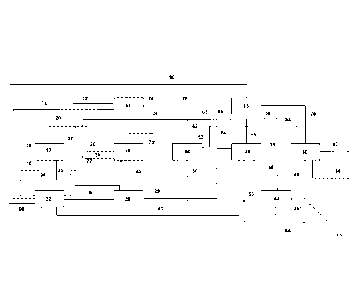
Fig. 1 is a schematic view of a system for producing synthetic fuels.
The system 10 shown in Fig. 1 for producing synthetic fuels comprises:
25 a) an apparatus 12 for separately extracting carbon dioxide and water
from ambi-
ent air having an air supply line 14 and an exhaust air line 16,
b) a synthetic gas production apparatus 18 for
producing a raw synthesis gas
comprising carbon monoxide, hydrogen, carbon dioxide and water, the synthe-
sis gas production apparatus 18 having supply line 20 for carbon dioxide lead-
30 ing from the apparatus 12 for separately extracting carbon dioxide
and water
from ambient air, a supply line 22 for air and a supply line 24 for water or
water
vapor and a raw synthesis gas discharge line 25,
CA 03155106 2022-4-14
20
c) a separating apparatus 26 for separating carbon dioxide and water from
the
raw synthesis gas produced in the synthesis gas production apparatus 18 with
a carbon dioxide return line 27 that opens from the separating apparatus 26
into the supply line 20 for carbon dioxide leading from the apparatus 16 for
sep-
5 arately extracting carbon dioxide and water from ambient air to the
synthesis
gas production apparatus 18,
d) a Fischer-Tropsch apparatus 28 for producing hydrocarbons by means of a
Fischer-Tropsch process from the synthesis gas from which carbon dioxide and
water were separated in the separating apparatus 26, the synthesis gas being
10 supplied to the Fischer-Tropsch apparatus 28 via a synthesis gas
supply line 29
leading from the separating apparatus 26 to the Fischer-Tropsch apparatus 28,
e) a refining apparatus 30 for refining the hydrocarbons produced in the
Fischer-
Tropsch apparatus 28 to make the synthetic fuels, which refining apparatus is
connected to the Fischer-Tropsch apparatus via a hydrocarbon supply line 31,
15 1) a desalination apparatus 32 for desalinating water, the
desalination apparatus
32 having a water supply line 34 from the apparatus 12 for separately extract-
ing carbon dioxide and water from ambient air, a water supply line 36 from the
synthesis gas production apparatus 18 and a water supply line 38 from the sep-
arating apparatus 26 as well as a water discharge line 40 to the Fischer-Trop-
20 sch apparatus 28, and
g) a water purification apparatus 42 comprising a water
supply line 44 leading
from the refining apparatus 30 and a water supply line 46 leading from the
Fischer-Tropsch apparatus 28 in each case for purifying water produced
therein.
The system 10 further comprises a pre-reformer 48 for converting higher
hydrocar-
bons to methane, carbon oxides, water and hydrogen. A water vapor supply line
50
leading from the water purification apparatus 42 to the pre-reformer 48 leads
into the
pre-reformer 48. In addition, a supply line 52 for process gas and return gas,
which is
30 fed from the process gas discharge line 54 leading out of the refining
apparatus 30
and from the gas discharge line 56 leading out of the Fischer-Tropsch
apparatus 28,
CA 03155106 2022-4-14
21
leads into the pre-reformer 48. A part of the gas discharged from the Fischer-
Trop-
sch apparatus 28 is directed into the supply line 52, while the remainder is
dis-
charged from the system 10 via the torch line 58. A circulation line 62 leads
from the
pre-reformer 48 to the supply line 24 for water or water vapor and from there
to the
5 synthesis gas production apparatus 18 for supplying the methane, carbon
oxide, wa-
ter and hydrogen compounds formed in the pre-reformer 48 to the synthesis gas
pro-
duction apparatus 18. A water vapor return line 63 also leads into the supply
line 24
and is connected to a water vapor discharge line 64 leading from the Fischer-
Trop-
sch apparatus 28. The water vapor discharge line 64 branches into a water
vapor re-
10 turn line 63 and into an excess water vapor line 65 that leads away from
the water
vapor discharge line 64.
Finally, the system 10 also comprises a hydrogen production apparatus 66 as
well
as a hydrogen compression apparatus 68 for producing hydrogen required in the
re-
15 fining apparatus 30. A water supply line 70 and an air supply line 72
coming from the
desalination apparatus 32 lead into the hydrogen production apparatus 66. In
addi-
tion, the hydrogen production apparatus 66 has an exhaust air line 74 and a
hydro-
gen line 76 leading to the hydrogen compression apparatus 68. From the
hydrogen
compression apparatus 68, a hydrogen line 78 leads into the refining apparatus
30
20 and a water line 80 leads into the desalination apparatus 32.
The refining apparatus 30 comprises one or more isocracker reactors (not
shown), a
hydrogen stripper (not shown) and one or more distillation columns (not
shown). Fur-
thermore, the refining apparatus 30 comprises a kerosene line 82 and a
gasoline line
25 84.
In addition, waste water lines 86, 86', 86" lead from the desalination
apparatus 32,
from the Fischer-Tropsch apparatus 28 and from the water purification
apparatus 42.
Finally, the synthesis gas production apparatus 18 also has an exhaust air
line 74'.
During the operation of the system 10, the apparatus 12 for separately
extracting
carbon dioxide and water from ambient air is supplied with air via the air
supply line
CA 03155106 2022-4-14
22
16, from which air carbon dioxide and water are separated in the apparatus 12.
Re-
maining exhaust air is discharged from the apparatus 12 via the exhaust air
line 16,
whereas in the apparatus 12 the water is separated from the carbon dioxide by
con-
densation. The carbon dioxide separated off is fed via the supply line 20 into
the syn-
5 thesis gas production apparatus 18, to which water vapor containing
methane, car-
bon oxides and hydrogen and air is also supplied via the supply lines 24, 22.
In the
synthesis gas production apparatus 18, a raw synthesis gas comprising carbon
mon-
oxide, hydrogen, water vapor and carbon dioxide is produced, from which a
large
part of the water is separated off by condensation. The water separated off is
fed into
10 the desalination apparatus 32 via the water supply line 38, whereas the
raw synthe-
sis gas is fed into the separating apparatus 26 via the line 25. There, carbon
dioxide
is separated from the raw synthesis gas by absorption, which carbon dioxide is
fed
via line 27 into line 20 and via the latter into the synthesis gas production
apparatus
18. In addition, water is separated in the separating apparatus 26 by
condensation
15 from the raw synthesis gas, which water is conducted via the line 38
into the desali-
nation apparatus 32. The water separated off in the apparatus 12 is also
supplied to
the desalination apparatus 32 via the water supply line 34. Finally, the
purified syn-
thesis gas is fed via line 29 into the Fischer-Tropsch apparatus 28, in which
the syn-
thesis gas is converted to predominantly normal paraffin hydrocarbons. These
hydro-
20 carbons are fed via line 31 into the refining apparatus 30, in which
they are con-
verted to synthetic raw fuels by means of hydro-isomerization and cracking
(isoc-
racking), which synthetic raw fuels are then separated in the hydrogen
stripper and
separated into the kerosene and gasoline fractions in the one or more
distillation col-
umns of the refining apparatus 30, which fractions are discharged from the
system
25 10 via lines 82, 84. Water produced in the Fischer-Tropsch apparatus 28
and in the
refining apparatus 30 is fed via the lines 46, 44 into the water purification
apparatus
42, in which the waste water is purified by means of partial evaporation. The
reaction
carried out in the Fischer-Tropsch apparatus 28 is a very highly exothermic
reaction
that requires cooling. For this purpose, fully desalinated water from the
desalination
30 apparatus 32 is supplied to the Fischer-Tropsch apparatus 28 via the
water dis-
charge line 40, the reaction heat of the Fischer-Tropsch synthesis being
discharged
via the water vapor discharge line 64 by means of the generation of water
vapor.
CA 03155106 2022-4-14
23
Most of the water vapor is supplied to the synthesis gas production apparatus
18 via
the water vapor return line 63 and the supply line 24, whereas the excess
water va-
por is discharged from the Fischer-Tropsch apparatus 28 via the excess water
vapor
line 65 and is used, for example, to evaporate the waste water that runs from
the
5 Fischer-Tropsch apparatus 28 to the water purification apparatus 42 via
the water
supply line 46. The flow of water vapor discharged via the water vapor supply
line 50
leading to the pre-reformer 48 contains approx. 2% hydrocarbons, which are con-
verted in the pre-reformer 48 to methane, carbon oxides, water and hydrogen.
The
remaining purified waste water is fed to the municipal waste water treatment
facility
10 via line 86". In addition, return gas produced in the Fischer-Tropsch
apparatus 28
and process gas produced in the refining apparatus are fed via the lines 54,
56, 52
into the pre-reformer 48, in which higher hydrocarbons are converted into
methane,
carbon oxides, water and hydrogen. The flow produced in the pre-reformer 48,
which
comprises methane, carbon oxides, water and hydrogen, is fed to the supply
line 24
15 via the circulation line 62 together with the water vapor flow coming
from the water
vapor return line 63 and from said supply line to the synthesis gas production
appa-
ratus 18.
In the hydrogen production apparatus 66, hydrogen is produced from the air
supplied
20 via line 72 and the water supplied via line 70, which hydrogen is
supplied as a mix-
ture with water vapor via line 76 to the hydrogen compression apparatus 68, in
which
the hydrogen is compressed to the required pressure and at the same time the
water
contained is separated by means of condensation. While the compressed hydrogen
is supplied to the refining apparatus 30 via line 78, the separated water is
fed via line
25 80 to the desalination apparatus 32.
The present invention will be described below using an example that is
illustrative
but does not restrict the invention.
30 Example
CA 03155106 2022-4-14
24
The method according to the invention was simulated in a system shown in Fig.
1
and described above using the PRO/II (AVEVA) process simulation software for
the
production of 15,000 liters of kerosene per day. The following product streams
were
obtained for the individual lines:
No. Designation
kg/h Nnn3/h
14 Air supply line
9576623
Supply line for carbon dioxide to the
20 3941
synthesis gas production apparatus
Supply line for air to the synthesis gas
22 7093
production apparatus
Supply line for water or water vapor to
24 4137
the synthesis gas production apparatus
Raw synthesis gas discharge line to the
25 4407
separating apparatus
27 C.arbon dioxide return line from separat-
1216
mg apparatus
Synthesis gas supply line from the sepa-
29 rating apparatus to the Fischer-Tropsch 2794
apparatus
31 Hydrocarbon supply line 834
Water supply line from the apparatus for
separately extracting carbon dioxide and
34 4501
water from ambient air to the desalina-
tion apparatus
Water supply line from the synthesis gas
36 production apparatus to the desalination 552
apparatus
Water supply line from the separating
38 397
apparatus to the desalination apparatus
Water discharge line from the desalina-
40 tion apparatus to the Fischer-Tropsch 4415
apparatus
Water supply line from the refining ap-
44 paratus to the water purification appa- 3.2
rat us
Water supply line from the Fischer-Trop-
46 sch apparatus to the water purification 1413
apparatus
Water vapor supply line to the pre-re-
50 999
former
CA 03155106 2022-4-14
25
Supply line for fuel gas and return gas to
52
576
the pre-reformer
54 Fuel gas discharge line
65
56 Gas discharge line
547
58 Torch gas discharge line
37
62 Circulation line from the pre-reformer
1575
Water vapor return line from the
63 2562
Fischer-Tropsch apparatus
Water vapor discharge line from the
64 4349
Fischer-Tropsch apparatus
Excess water vapor line from the
65 1786
Fischer-Tropsch apparatus
Water supply line to the hydrogen pro-
70 172
duction apparatus
72 Air supply line
21130
Hydrogen line to the hydrogen compres-
76 20.7
sion apparatus
78 Hydrogen line to the refining apparatus
18.9
Water discharge line to the desalination
80 1.8
apparatus
82 Kerosene line
484
84 Gasoline line
300
865
86 Waste water line
66
86 Waste water line
418
86" Waste water line
CA 03155106 2022-4-14
26
List of reference signs
system for producing synthetic fuels
12 apparatus for separately extracting
carbon dioxide and water from
5 ambient air
14 air supply line
16 exhaust air line
18 synthesis gas production apparatus
supply line for carbon dioxide to the synthesis gas production appa-
1 0 ratus
22 supply line for air to the synthesis gas
production apparatus
24 supply line for water or water vapor to
the synthesis gas production
apparatus
raw synthesis gas discharge line to the separating apparatus
15 26 separating apparatus for separating carbon dioxide and
water from
raw synthesis gas
27 carbon dioxide return line from
separating apparatus
28 Fischer-Tropsch apparatus
29 synthesis gas supply line from the
separating apparatus to the
20 Fischer-Tropsch apparatus
refining apparatus
31 hydrocarbon supply line
32 desalination apparatus
34 water supply line from the apparatus for
separately extracting carbon
25 dioxide and water from ambient air to the desalination
apparatus
36 water supply line from the synthesis gas
production apparatus to the
desalination apparatus
38 water supply line from the separating
apparatus to the desalination
apparatus
30 40 water discharge line from the desalination apparatus to
the Fischer-
Tropsch apparatus
CA 03155106 2022-4-14
27
42 water purification apparatus
44 water supply line from the refining
apparatus to the water purification
apparatus
46 water supply line from the Fischer-
Tropsch apparatus to the water pu-
5 rification apparatus
48 pre-reformer
50 water vapor supply line to the pre-
reformer
52 supply line for process gas and return
gas to the pre-reformer
54 process gas discharge line
10 56 gas discharge line
58 torch gas discharge line
62 circulation line from the pre-reformer
63 water vapor return line from the Fischer-
Tropsch apparatus
64 water vapor discharge line from the
Fischer-Tropsch apparatus
15 65 excess water vapor line from the Fischer-Tropsch
apparatus
66 hydrogen production apparatus
68 hydrogen compression apparatus
70 water supply line to the hydrogen
production apparatus
72 air supply line
20 74, 74' exhaust air line
76 hydrogen line to the hydrogen compression
apparatus
78 hydrogen line to the refining apparatus
80 water discharge line to the desalination
apparatus
82 kerosene line
25 84 gasoline line
86, 86', 86" waste water line
CA 03155106 2022-4-14