Note: Descriptions are shown in the official language in which they were submitted.
WO 2021/086201 PCT/NZ2019/050145
1
IMPROVEMENTS IN, OR RELATING TO, SLIDING SPOOL VALVES, AND METHODS
THEREFOR
TECHNICAL FIELD OF THE INVENTION
5 The present invention relates to a sliding spool valve.
In particular, though not solely, the present invention is directed to a
sliding spool valve for
use in air or fluid operated tools or machines or the like.
10 BACKGROUND OF THE INVENTION
Sliding spool valves are often used in pneumatic and hydraulic fluid control
systems.
For example pneumatic or hydraulic solenoid, pilot (pneumatic or pneumatic),
spring, or
manually actuated sliding spool valves are used to control large oil and gas
valves with
15 pneumatic actuators fitted, and in large hydraulically powered
construction equipment
They are also used to trigger pneumatic triggering arrangements in air
operated tools and
equipment such as nail guns.
20 A spool valve typically has a piston or the like shape contained within
a bore. The piston
can slide within the bore and is fluidly sealed to the bore, to allow sliding
of the piston, but
under normal conditions of use remains fluidly sealed to the bore. The
movement of the
piston then will open one or more supply or exhaust ports to the bore, to
allow fluid to
move across or along the bore to one or more exhaust or supply ports. In doing
so the
25 piston may also close off access from one or more supply or exhaust
ports to one or more
exhaust or supply ports. Thus it can not only serve as an open or closed
valve, but may
redirect fluids as needed depending on its linear position relative to the
exhaust ports and
inlet ports arrangement.
30 Frequently piston mounted seals are used. These seals are 0-rings, lip
seals, or similar
seals, that are mounted to a piston, for example within a locating groove, and
then
compressed between the bore and the piston to form the fluid seal. In
hydraulic systems,
sections of the bore which are sufficiently close in diameter to that of the
piston can also
act as seals, due to the viscosity of the operating fluid being enough to
heavily restrict flow
35 along the gap between the piston and bore, effectively creating a seal.
In this manner it is
reasonable that a rigid member can be a seal.
CA 03156608 2022-4-28
WO 2021/086201 PCT/NZ2019/050145
2
Several problems arise with piston mounted seals.
The first of these is assembly. The seal must be located in place on the
piston into the
5 locating groove. This can be simple when the piston is simple in shape,
and or the
locating groove is close to one end of the piston and there is nothing between
that end
and the locating groove that that o ring cannot stretch over. However, when
the locating
groove is further down the piston, or there are several seals to assemble, or
small
diameter seals must be stretched over large sections of the piston, for
example in a multi-
10 port arrangement, then moving the o-rings into position can be
difficult, as the seals must
pass over each locating groove, until they are in the correct one. This
assumes the seals
are o-rings and can stretch. If the seals, whether o-rings or not, cannot
stretch, or have
very limited stretch, then such assembly is even more difficult, if not
impossible, thus
limiting the design options available. Split seals can assist with this
assembly issue as
15 they can be opened analogous to stretching an o-ring, but these seals
inherently have a
leak path and therefore are not always applicable.
Likewise when the valve needs maintenance then removing the seals is
difficult, and will
often result in the need to replace the seal, even when perfectly serviceable
due to the
20 limited methods available to lift a seal out of its locating groove
without damaging it.
Further the locating grooves, or other piston features, or other bore other
features, often
have sharp edges, thus moving the seal over the sharp edge can damage the
seal, this
occurs whether during assembly or maintenance.
A further drawback of piston mounted seals is that when the seal is mounted on
the piston
it must then be compressed into the bore with the piston during assembly_ Even
for a
single seal this can create significant sliding friction mentioned below, and
can run the risk
of damaging the seal on a locating groove edge, or on the entrance to the
bore, or on
30 some other feature in the bore. This is worse still if the seal is
pinched between the bore
and piston, rendering the seal inoperative, leaky, or with a reduced service
life.
Also piston mounting the seals presents a problem in available sizing of the
seals, and
available seal selection, to reduce stiction. Stiction is the friction
associated with the static
35 friction of the seal compressed against the sliding surface within the
bore, and must be
overcome to move the piston relative to the bore. Limited seal selection
options can
greatly increase the required compression force requirement to generate an
effective seal.
CA 03156608 2022-4-28
WO 2021/086201 PCT/NZ2019/050145
3
In general, the greater me compression required to generate a reliable seal,
the greater
the stiction. Compression force is made significantly higher when a seal must
be pre-
loaded by a distance that is a significant proportion of it's cross sectional
thickness. The
greater the stiction, the greater the actuation component, pressure area,
force, or
5 mechanism that must be used to slide the piston relative the bore. This
may be
acceptable in large machinery where there is ample space, or where high
activation force
is available. However, where the application requires lower cost, or there is
little room for
high power actuators, or where the actuation is by hand of a user, this is
disadvantageous.
One way to reduce seal stiction for a given pressure rating and seal type is
to reduce the
absolute or relative (to cross section thickness) compression of the seals. A
convenient
way to achieve this is by using larger sealing elements. When the seal is
piston mounted
this can only be done by increasing the size of the locating groove, that is
by
15 manufacturing the groove deeper and wider into the thickness of the
piston. This can only
go so far before the mechanical strength of the piston is compromised due to
the
reduction in diameter at the locating groove.
A further disadvantage of piston mounted seals is that the bore becomes the
wear
20 surface. If the wear surface is damaged, or wears out, through
operation, or is damaged
through maintenance activities, then the entire apparatus that has the bore
located in it
must be replaced. This can be expensive, not only in equipment, but also in
labour, in
multiport operations, and where the apparatus is complex.
25 In alternative assemblies gland seals are used which are located in
machined grooves
within the bore, or are mounted between rigidly connected components which
between
them form the groove to retain the seal.
A similar problem occurs here where the seal must be located into the bore,
particularly
30 where piston diameters and bore diameters are small, a bore is deep,
seal thickness is
high, and there are many seals. In these cases assembly and servicing becomes
challenging, time consuming, and often impractical. Where bore mounted seals
are used,
they mounted in manufactured grooves on the bore. Grooves are generally
machined into
bores made of metals but can also be cast or otherwise formed into bores made
of
35 plastics, metals, ceramics, or any other suitable materials. If multiple
components are
used to constrain a seal, thereby forming a groove, those components are
rigidly mounted
relative to the bore. Again seals may be compromised when locating them into
the groove
CA 03156608 2022-4-28
WO 2021/086201 PCT/NZ2019/050145
4
within the bore, and or when the piston is slide home dunng assembly, or
removed tor
disassembly.
It is easier to increase locating groove size when the seal is bore mounted,
however there
5 still must be sufficient material in the bore to allow this_ The main
problems with increasing
groove size in bores are:
1.) when the bores are not large increasing groove and seal size makes
assembly
more difficult.
10 2.) Machining deep grooves into small bores is difficult,
requires special tooling,
and are challenging from a QA/Measurement perspective. These problems are
made worse when many are needed to form a multiport valve. This is a
disadvantage of bore mounted seals, also known as glands, or gland seals.
15 An additional benefit of using large cross section o-rings is that it
reduces the precision to
which the bore and piston must be manufactured. Where smaller cross section
sealing
elements are used they are easier to assemble, especially in grooves
manufactured into
bores, but the gap between the piston and bore must be more tightly controlled
for reliable
sealing operation at a given pressure. The higher the pressure, the smaller
the gap must
20 be for a given seal. Larger cross section seals may also be able to wear
more than thin
section seals, and continue operating as intended.
Enabling easy assembly, disassembly or service of compact spool valves
suitable for high
and low pressures, using large cross section seals, and with low piston
stiction, with lithe
25 or no specialised tools or labour is therefore desirable.
Further in a multiport situation then the design is often limited to either
piston or gland
mounted seals, combinations cannot be used as they will foul each other on
assembly
and disassembly, unless reducing diameters are used. If they are used, then
this again
30 limits the design and pressure that can be handled.
In this specification where reference has been made to patent specifications,
other
external documents, or other sources of information, this is generally for the
purpose of
providing a context for discussing the features of the invention. Unless
specifically stated
35 otherwise, reference to such external documents is not to be construed
as an admission
that such documents, or such sources of information, in any jurisdiction, are
prior art, or
form part of the common general knowledge in the art.
CA 03156608 2022-4-28
WO 2021/086201 PCT/NZ2019/050145
It is an object of the present invention to provide an improved spool valve,
or to provide
more flexibility in design for spool valves, or reduce the assembly, operation
and
maintenance cost, or to provide for more compact assemblies, or to overcome
the above
5 shortcomings or address the above desiderata, or to at least provide the
public with a
useful choice.
BRIEF DESCRIPTION OF THE INVENTION
In a first aspect the present invention may be said to broadly consist in a
spool valve to
10 valve a fluid between at least one inlet port and at least one outlet
port, having a bore with
a spool operably associated therein, comprising or including,
The bore, having one or more of the at least one inlet port and at least one
outlet
port,
At least one in-bore seal located in the bore, the at least one in-bore seal
fluidly
15 sealing on a seal outer diameter to an inside diameter of the bore, and
selectively fluidly
sealing on a seal inside diameter to a spool outside diameter,
At least one spacer located in the bore, adjacent the at least one in-bore
seal
having a fluid communication from a spacer internal diameter to a spacer
external
diameter and with the at least one inlet port, or the at least one outlet
port,
20 A removable retention component retaining the at least one spacer
and the at least
one in-bore seal within the bore,
The spool, slidingly mounted within the bore to translate along a major
longitudinal
axis of the bore, having,
a first position where the spool prevents fluid flow from the at least one
inlet
25 port to the at least one outlet port by fluidly sealing to the at
least one in-bore seal,
and
at least a second position, where the spool allows fluid flow from the at
least one inlet port to the at least one outlet port by unsealing from the at
least one
in-bore seal,
30 Such that a spool valve is formed to allow or deny fluid flow
across the valve.
Preferably the valve either allows or prevents fluid flow, but cannot vary the
fluid flow.
Preferably there is a second in-bore seal located outwardly a bore entrance.
Preferably the at least one spacer lies directly over, or in line with, the at
least one inlet
port, or at least one outlet port, it is in fluid communication with.
CA 03156608 2022-4-28
WO 2021/086201 PCT/NZ2019/050145
6
Preferably the spool has a third position where it allows, or prevents, flow
from other, or
the same, of the inlet ports to the same, or other, of the outlet ports, or
vice versa.
5 Preferably there are multiple in-bore seals.
Preferably each of the multiple in-bore seals seals, whether selectively or
not, to a
respective spool outside diameter.
10 Preferably there is a spacer between each of the multiple in-bore seals.
Preferably the spool contains one or more of the at least one inlet ports, or
one or more of
the at least one outlet ports.
15 Alternatively the bore contains all the inlet ports and all the outlet
ports.
Preferably the spool is externally actuated by an actuator on one end at or
towards a bore
entrance.
20 Preferably the spool is biased in a first direction by an elastic
element, such as for
example, but not limited to, a spring.
Preferably the spool is moved in a second direction, opposite the first, by
fluid pressure on
the spool, or part thereof.
Preferably the spool has an engagement end, at or toward an external entrance
to the
bore, and an operative end, distal from the engagement end, located within the
bore at
least for the first position or the second position.
30 Preferably the engagement end is a piston.
Preferably the actuator acts on the operative end.
Preferably fluid pressure can act on the piston to slide the spool from the
first position to
35 the second position, or vice versa.
Preferably a, or the, spool outer diameter is supported on a spacer inner
diameter of the
CA 03156608 2022-4-28
WO 2021/086201 PCT/NZ2019/050145
7
first spacer acting as a support or guide surtace.
Preferably the spacers are separate to the respective in-bore seal(s) they
space apart
5 Alternatively one or more of the spacers is connected to at least one of
the in-bore seals it
spaces.
Preferably the fluid communication is provided by at least one aperture
through from the
spacer internal diameter to the spacer external diameter.
Preferably the external diameter is recessed about the external periphery of
the spacer, to
provide the fluid communication from the at least one aperture to the at least
one inlet
port, or at least one outlet port.
15 Preferably the components of the in-bore seal(s), spacer(s), are
removable by slidingly
removing from the bore along the major longitudinal axis once the retention
component is
removed.
Preferably removal of the retention component also allows removal of the
spool.
Preferably there is at least one permanent in-bore seal fluidly sealing
between the bore
and in sliding sealing contact on an external surface of the spool.
Preferably sealing is achieved through radial pressure of the in-bore seals
against the
25 inner diameter of the bore, and outer diameter of the spool, in other
words sealing occurs
on surfaces parallel to the major longitudinal axis.
Preferably the in-bore seal(s) have any one of a circular, square, or lip seal
cross section.
30 Preferably a leading edge and or trailing edge of the sealing surface of
the external
diameter is tapered to provide a transition for the in-bore seal when sealing
and unsealing
to the external diameter.
Preferably the in-bore seals only apply pressure in the longitudinal direction
directly on the
35 bore, or a spacer, but not on another in-bore seal, whether directly or
indirectly.
Preferably the spool contains one or more passage, whether open along their
length, or
CA 03156608 2022-4-28
WO 2021/086201 PCT/NZ2019/050145
8
closed to tne spool outside diameter mat allows additional tiow patn tor tne
Hula.
In another aspect the present invention may be said to broadly consist in a
method of
providing a spool valve to valve a fluid between at least one inlet port and
at least one
5 outlet port,
Comprising or including the steps of,
Providing a bore having one or more of the at least one inlet port and at
least one
outlet port, the bore having one
Sliding a spool linearly at least in part within the bore,
10 Sealing an internal diameter of the bore, using at least one in-
bore seal, between
the internal diameter and in selective sliding engagement with an external
diameter of the
spool,
Spacing the at least one in-bore seal within the bore using at least one
spacer,
Retaining the at least one in-bore seal, the at least one spacer, and the
spool
15 within bore, such that at least one spacer retains the at least one in-
bore seal,
Sliding the spool so that it is in selective sliding engagement between a
first
position where the external diameter is clear of the at least one in-bore seal
to allow fluid
flow from the at least one inlet port, to the at least one outlet port, and a
second position
where the external diameter is sealed to the at least one in-bore seal to
prevent fluid flow
20 from the at least one inlet port, to the at least one outlet port,
Such that a spool valve to control fluid flow is provided.
Preferably the method includes sealing on the external diameter through radial
forces.
25 In another aspect the present invention may be said to broadly consist
in a spool valve to
valve a fluid, comprising or including,
A bore having one or more inlets, and one or more outlets,
A spool slidingly operable within the bore,
One or more in-bore seals contained within the bore the in-bore seal fluidly
sealing
30 on a seal outer diameter to an inside of the bore, and selectively
fluidly sealing on a seal
inside diameter to a spool outside diameter,
At least one spacer located in the bore, adjacent the at least one in-bore
seal
having a fluid communication from a spacer internal diameter to a spacer
external
diameter and with the at least one inlet port, or the at least one outlet
port,
35 A removable retention component retaining the at least one spacer
and the at least
one in-bore seal within the bore,
Wherein the spool slides between at least two positions, a first of which
prevents
CA 03156608 2022-4-28
WO 2021/086201 PCT/NZ2019/050145
9
flow trom at least one or the one or more inlets, to at least one or more ot
the outlets via a
sealing of at least one of the in-bore seals on at least one spool outside
diameter, and a
second of which allows flow from at least one of the one or more inlets, to at
least one or
more of the outlets by an unsealing of at least one of the in-bore seals on at
least one
5 spool outside diameter.
In another aspect the present invention may be said to broadly consist in a
spool valve
as described herein with reference to any one or more of the accompanying
drawings.
10 In another aspect the present invention consists in a method of
providing a spool valve
as described herein with reference to any one or more of the accompanying
drawings.
In another aspect the present invention consists in a kit of parts for
servicing or
retrofitting an existing spool valve as described herein with reference to any
one or
15 more of the accompanying drawings.
As used herein the term "and/or" means "and" or "or", or both.
As used herein "(s)" following a noun means the plural and/or singular forms
of the noun.
The term "comprising" as used in this specification means "consisting at least
in part of.
When interpreting statements in this specification which include that term,
the features,
prefaced by that term in each statement, all need to be present, but other
features can
also be present. Related terms such as "comprise" and "comprised" are to be
interpreted
25 in the same manner.
It is intended that reference to a range of numbers disclosed herein (for
example, 1 to 10)
also incorporates reference to all rational numbers within that range (for
example, 1, 1.1,
2, 3, 3.9, 4, 5, 6, 6.5, 7, 8, 9 and 10) and also any range of rational
numbers within that
30 range (for example, 2 to 8, 1.5 to 5.5 and 3.1 to 4.7).
The entire disclosures of all applications, patents and publications, cited
above and below,
if any, are hereby incorporated by reference.
35 This invention may also be said broadly to consist in the parts,
elements and features
referred to or indicated in the specification of the application, individually
or collectively,
and any or all combinations of any two or more of said parts, elements and
features, and
CA 03156608 2022-4-28
WO 2021/086201 PCT/NZ2019/050145
where specific integers are mentioned herein which have known equivalents in
the art to
which this invention relates, such known equivalents are deemed to be
incorporated
herein as if individually set forth.
5 Other aspects of the invention may become apparent from the following
description which
is given by way of example only and with reference to the accompanying
drawings.
BRIEF DESCRIPTION OF THE DRAWINGS
Preferred forms of the present invention will now be described with reference
to the
10 accompanying drawings in which;
Figure 1 A Shows a partial cross section through
a typical piston mounted seal in a
location groove, in sliding sealing contact with an internal diameter of a
bore,
B Shows a similar cross section to Figure 1A, but where the seal is
mounted in a gland style on the bore, and is in sliding sealing contact with
an external diameter of the piston,
20 C shows a static non-sliding face seal between two
component,
Figure 2 Shows a vertical cross section through
an assembly in keeping with the
present invention, showing the bore in an apparatus, the spool, in-bore
seals, spacers, inlet ports, outlet ports, and retention component,
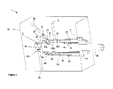
Figure 3 Shows a similar view to that of Figure
2, but in isometric view,
Figure 4 Shows an exploded view of the assembly
of Figure 2 and 3,
30 Figure 5 Shows a close up of the spool, spacers, and in-bore
seals and driving
element,
Figure 6 Shows an exploded diagram of Figure 5
showing one form of the spool,
35 Figure 7 Shows a cross section of Figure 5,
CA 03156608 2022-4-28
WO 2021/086201 PCT/NZ2019/050145
11
Figure 13 Shows an isometric view ot the spacer,
Figure 9 Shows an alternative version of the
spool in isometric view, where there are
additional grooves, in this case to a common volume,
Figure 10 Shows a vertical cross section of a
further alternative spool similar to Figure
9, showing alternative flow paths a passageways from one area of the
spool to another,
Figure 11 Shows a close up of the alternative flow paths of Figure 10,
Figure 12 Shows a cross section through the
apparatus showing the bore and inlet
and outlet ports,
Figure 13 A shows the spool valve in vertical cross section with the
spool in a first
position, and
B shows the spool valve in vertical cross section with the spool in a second
position.
DETAILED DESCRIPTION OF THE INVENTION
Types of sealing arrangements for linear sliding, or spool valves are shown in
partial cross
section in Figure 1A through 1C. Figure 1A shows the seal 6 mounted within a
locating
groove 30 on a piston 25. The piston 25 and seal 6 are mounted within a bore
4, and can
slide along longitudinal axis 15. The seal 6 is compressed between the bore
and the
piston to retain a fluid on a seal first side 31 at a first pressure and
prevent it from moving
to the seal second side 32, at a second pressure.
Figure 1B shows a similar arrangement to that of Figure 1A except the seal 6
is mounted
within a groove 30 on the bore 4. Again the piston 25 slides along the
longitudinal axis
15, and in this case the seal 6 is stationary, relative to the piston 25.
A static example, for comparison, is shown in Figure 1C where a seal 6 is
mounted in a
groove 30 and is compressed between two components, again to prevent a fluid
at a first
pressure on a first side 31 from moving to a second side 32 at a second
pressure.
CA 03156608 2022-4-28
WO 2021/086201 PCT/NZ2019/050145
12
Preferred embodiments will now be described with reterence to Figures 2
through 13.
The spool valve us a sliding or linear action movement fluid control valve of
the type that
has more than one distinct stable position in which the available flow paths,
for example
from inlet port 2 to outlet port 3 through the valve are distinct from at
least one of the other
5 stable positions_
A linear sliding or spool valve 1 in keeping with the present invention is
shown in Figure 2
through 13.
10 A cross section of a spool valve 1 is shown in Figures 2 and 3. The
spool valve 1 consists
of a bore 4 within a body 33, for example in apparatus, or a valve body or
similar.
Typically the bore 4 is circular in cross section. However, it may be any
shape that a
corresponding spool 5, seals 6 and spacers 10 can confirm to and valve in
(described
below). The bore has an inlet port 2, and two outlet ports 3A and 3B, that are
in fluid
15 communication with the bore 4. The bore 4 may be drilled, bored,
machined, or
otherwise manufactured in the body 33. As shown it may be of a single or
various internal
diameters 35 or cross sections in a metal, polymer, ceramic, or composite
material body
33. The bore 4 may be blind and partially threaded 34 as shown at one end.
Alternatively
the bore 4 may be open at both ends and then closed by another body sealed
thereto.
20 The bore 4 as shown may be a blind one, that is there is a bore entrance
20, and no exit
other than the fluid inlets 2 and outlets 3. In other forms the bore may be
open at either
end, that is it has two bore entrances 20, one at each end, whether through a
single body
33, or two or more bodies 33 connected together.
25 The fluid inlet port(s) 2 and fluid outlet port(s) 3 may connect the
bore to the atmosphere,
pressure supplies, enclosed volumes, or flow paths that require the valved
fluid(s). As
shown there may be more than one inlet 2 or outlet 3 separated along the
bore's 4
longitudinal axis 15 and the inlets 2 and outlets 3 may be at any angle and at
any
orientation along the bore. As shown the inlets 2 and outlets 3 open onto the
bore 4
30 circumference, that is its inside diameter 35.
Within the bore 4 is a spool 5 that matches the cross-section of the bore 4,
though it is of
reduced diameter to that of the bore. The spool 5, in the embodiment shown is
biased in
the position by a biasing element 21 such as a spring. However, in other
embodiments
35 there may be no biasing element, and the spool is moved as needed by an
actuator
whether internal or external to move the valve into the required position. For
example the
actuator 19 may act on the engagement end 46 of the spool. In the form shown
the
CA 03156608 2022-4-28
WO 2021/086201 PCT/NZ2019/050145
13
biasing element 21 bears on a portion, in this case a spool shoulder 41 ot the
spooi 5 and
a retention component 14. The spool 4 also optionally has a piston 25, which
operation is
described later, at an operative end 45. The spool 5 is centrally located on
the
longitudinal axis 15 and is moveable so it can slide or translate along the
axis 15. The
5 spool 5 has one or more cylindrical sealing surfaces 36 on its outer
diameter a The spool
has no grooves or similar and does not retain an o-ring or other form of seal
6 in the
sliding axis. The sealing surfaces 36 are parallel with the axis of movement,
along the
longitudinal axis 15, of the spool 5. The spool 5 is shaped and sized such
that it
encounters a limit to it's motion in both directions along the longitudinal
axis via a
10 component rigidly connected to the body in some manner for example the
retention
component 14 in a direction toward the bore entrance 20, or by encountering
the body of
the bore for example, in the opposing direction.
As shown the spool 5 has several changes in diameter 9 providing lands 43 to
engage the
15 seals 6, and undercuts 44 to allow fluid flow past the seal 6. The
leading edge 27 and
trailing edge 28 of the changes in diameter are tapered, or as shown, rounded
29. The
reason for this is explained shortly.
Further variations of the spool 5 are shown in Figures 9 through 11. Rather
than, or in
20 addition to, undercuts to allow fluid flow there is at least one passage
47, and preferably
several running along the spool 5. The passage 47 may be formed as a groove
forming
an open passage 47 that fluidly communicates into a common volume 50 as shown
in
Figure 9. Alternatively the passage 47 may be close formed as a connecting
fluid
pathway, with an opening 48 and an exit 49 in any direction from one region of
the spool
25 to another as shown in Figures 10 and 11.
The passage 47 may allow additional flow area for the fluid, for example when
the spool 5
diameter becomes too small. Additionally, or alternatively the passage(s) 47
may allow
additional flow paths that miss one or more seals or inlet or outlet ports to
provide
30 additional valving functionality that would not be present if the flow
path was only along
the spool outside diameter 9.
Such variations as shown of the spool 5, may be made by machining, or additive
manufacturing to provide the passage(s) 47.
As shown there are a number of in bore seals 6 within the bore 4. The seal
outer
diameter 7 seals against the adjacent bore inside diameter 35. The seal inside
diameter 8
CA 03156608 2022-4-28
WO 2021/086201 PCT/NZ2019/050145
14
seals against the adjacent spool outside diameter 9. As the seal 6 is
compressed
between these two diameters it forms a seal against fluid moving from a seal
first side 31
to a seal second side 32. The spool 5 moves linearly relative to the in bore
seals 6, and
the in-bore seals 6 are stationary in relation to the bore 4. The seal inside
diameter 8 is in
5 sliding sealing contact with the spool outside diameter 9, at least when
in contact there
with.
Such sealing contact can happen in at least two situations_ The first is where
the in bore
seal 6 is always in contact with the spool outside diameter, such as in-bore
seal 6a.
10 Although the spool 5 will move relative the in bore seal, at no point in
normal operation of
seal 6a will it be free of the sealing surface 36A on the spool 5. Spool
valves will
frequently include these types of seals 6 which are never disengaged, and act
to
permanently separate chambers or eliminate flow paths. For example as shown in
Figure
2 seal 6A has the function of preventing fluid on its in-bore side from
leaking to
15 atmospheric, that is to the bore entrance 20.
The second form of sealing contact, selective sealing and unsealing is based
on the
translation of the spool 5 and optionally variations in the spool outside
diameter 9. The
spool 5 as shown and described can have various reduced diameter portions 9,
grooves,
20 or internal flow paths adjacent cylindrical sealing surfaces 36,
allowing for selective
sealing and unsealing as the spool 5 moves from a first position 16 to a
second position
17, such as shown in Figure 13. For at least one sealing element 6c or 6B in
Figures 2
and 3, when disengaged from the sealing surface 36, due to movement of the
spool 5, it
encircles a reduced diameter, section, or shape portion of the movable sealing
element.
25 Therefore, sealing surface 36B can become free of in bore seal 6C as the
spool slides
under normal operation to the position shown. In contrast with sufficient
translation to the
left in Figures 2 and 3, the spool 5 can be clear of seal 6B and allow fluid
to pass from port
2 to port 3A, such as shown in Figure 13A.
30 The sealing surface 36 is parallel to the motion of the spool 5, the
seal does not and
cannot rely on directly generating compressive load on the seal 6 in the
direction of
movement of the spool 5 to create a seal, the seal is only formed by the
compression of
the seal radially between the bore inside diameter 35 and the spool outside
diameter 9.
The sealing surface (seat) can be an internal cylindrical surface, or an
external surface.
35 The seal is not by the movement of the moving element compressing the
seal 6 in the
direction of the moving element in order to create the seal. The elastic
element of the seal
6, when in a sealing position, is compressed or stretched entirely
perpendicularly to the
CA 03156608 2022-4-28
WO 2021/086201 PCT/NZ2019/050145
longitudinal axis 15, that is radially, in order to create the seal between
the bore 4 and me
spool 5. That is, to generate a seal from the unsealed state the movement of
the spool 5
makes the seal 6 encounter a cylindrical (or other locally constant & smooth
cross section)
sealing surface 36 with an appropriately ramped or rounded, rounded, ribbed,
or special
5 geometry lead-in edge or surface 27 or lead out edge or surface 28 to
allow the smooth
transition of the seal 6 from sealing to not sealing, or from not sealing to
sealing on the
spool 5.
The maximum amount of reduction in diameter, or the newly introduced flow path
size, is
10 related to the cross sectional thickness of sealing elements 6. The
reduction in diameter in
relation to the sealing diameter, or the flow area of a groove or other
introduced flow path
through or around the spool 5 shall not exceed the cross sectional thickness
of the sealing
element, and will typically be a small fraction of that thickness, say between
10 and 30%
of that dimension.
To allow easy transition of the seal 6 onto and off the sealing surface 36 the
leading edge
27 and trailing edge 28, as described above are tapered or rounded 29. This is
also a
useful feature to allow for easy of assembly and disassembly and reduces the
likelihood of
seal damage. Various cross section or composite sealing elements are viable in
this
20 application.
The seals 6 are most typically 0-rings made of nitrile rubber or other
polymer. Less
commonly the seal 6 will be comprised of non-circular section sealing elements
such as
lip seals, square section seals. In hydraulic arrangements seals 6 may be
comprised of
25 accurately manufactured rigid sealing faces, features, or bodies using
small gap viscous
flow to generate sufficiently effective sealing. Materials can also vary
widely and can even
be made of composite materials or multiple materials.
Present also is a floating spacer 10 between, and separating the, in bore
seals 6 as
30 shown in Figures 8 and 5. The spacer 10 is not fixed to the bore inside
diameter 35, and
is hence floating. Instead it is sandwiched between the seals 6 and the
retention
component 14 (described shortly). In the preferred form the spacer 10 can
slide into place
as part of assembly of the spool valve 1, and slide out of place as part of
the disassembly
of the spool valve 1, as shown in Figures 4, 6 and 7. In some forms the spacer
10 may be
35 an interference fit with the bore, however this is not as desirable as
it may cause
assembly and disassembly issues.
CA 03156608 2022-4-28
WO 2021/086201 PCT/NZ2019/050145
16
i he spacer 101 seal 6, retention component 14, and bore length are sized such
that once
they are assembled into the valve the seals 6 and spacers 10 can only move a
small
amount along the longitudinal axis. The amount of free movement of spacers 10
or seals
6 within the bore 4 in the assembly is sufficiently low such that there is no
position
5 available, when pressurised or depressurised, where a seal 6 can interact
with a port 2 or
3 which is in alignment with a spacer 10. The enable assembly there is free
movement,
but this is generally less than the cross sectional thickness of a sealing
element 6.
Once pressurised under normal operation, the free movement of floating spacers
10 may
10 increase substantially due to the pressure force compressing a seal or
seals 10 away from
the adjoining floating spacer(s) 10, thereby allowing it additional free
movement within the
bore 4. In these cases, the movement of seals 6 and adjacent floating spacers
10 due to
pressure is designed to not cause or allow a seal 6 to interact with a port 2
or 3.
15 In other forms there is a compression fit longitudinally of the seals 6
and the spacers 10
such that there is no free movement of the seals 6 and spacers 101 other than
due to
deformation of the seals 6 during translation of the spool 5.
The arrangement of the spacers 10, seals 6, and inlet ports 2 and outlet ports
3 is such
20 that the seals are not located over the ports 2 and 3. Working from
right to left in Figure 2,
seal 6A is clear of inlet port 2, and is prevented from moving over the inlet
port 2 by the
spacer 10A. Likewise seal 6C is held clear of inlet port 2 and outlet port 3A
by spacers
10A and 10B. Seal 6B is prevented from moving over outlet port 3A by spacer
10B, and
from moving over outlet port 3B by the shoulder 37. In this way the seals 6
when
25 assembled are located between or beyond (but not in contact with) the
drilled or otherwise
manufactured inlet and outlets 2 and 3 respectively in the bore 4.
The spacers as shown in Figure 8 have a spacer internal diameter 12 and a
spacer
external diameter 13. The spacer external diameter 13 as described is a close
or
30 interference fit with the bore internal diameter 35, at least such that
it is largely prevented
from moving radially. Likewise the spacer internal diameter 12 is a close fit
with the spool
outside diameter 9. In this way the spacer may have a finished internal
diameter 12,
whether hardened, polished or coated, to provide a support or guide surface 38
with the
spool outside diameter 9. Likewise the spool outside diameter 9 may also, or
instead of,
35 be hardened, polished or otherwise coated, to provide as low friction
surface as possible
against the seals 6, and spacers 10.
CA 03156608 2022-4-28
WO 2021/086201 PCT/NZ2019/050145
17
he spacers 1i.) and their external diameter 13 and me bore inside diameter 35
and
shoulders 37 interact such that the force generated by pressure contained by a
seal 6, is
not passed through to another seal 6 before being transmitted to the body or
other rigidly
mounted member.
In other words when a pressure force (or net pressure force) acts on a seal 6
to slide it
along the bore 4 towards a port 2 or 3, if the seal is adjacent a spacer 10,
then that spacer
is supported such that the seal 6 cannot interact with that port 2 or 3. The
force that
restrains that spacer 10 to prevent the seal 6 engaging the port 2 or 3 has to
come from
10 somewhere - either the bore itself for example from a
shoulder 37 or other feature,
another rigidly mounted component, or by another seal 6 in compression. This
preferred
form is illustrated in Figures 13A and B, where a seal 6 does not directly or
indirectly
support (via a spacer 10) another seal 6; in no position or pressure state
does a force
generated by a seal 6 as a result of pressure, act through another seal 6.
Therefore
ideally seals 6 only generate forces by restraining pressure, they don't
transmit a force
generated by pressure and act on another seal 6.
In Figure 13A the force 42 acting on the spacers 6A and 6B is shown in the
longitudinal
direction. For seal 6A this force is taken by the retention component 14. For
seal 6B the
force 42 is against the spacer 1013, which in turn bears on shoulder 37A. In
Figure 13B
again the force 42 for seal 6A is taken by the retention mechanism 14. For
seal 6C the
force 42 is taken by the seal 6C bearing directly on shoulder 376.
While in the present invention we could pass these loads through seals 6, it
is preferable
in terms of seal life and ease of actuation.
In the preferred form the way to restrict movement, and constrain pressure
force, is to use
shoulders 37 in the bore 4, or other rigidly mounted components, and generally
not by
compressively loading another seal.
As shown in Figure 8 there is a fluid path 11 from the spacer internal
diameter 12 to the
spacer external diameter 13. In the embodiment shown there are a plurality of
apertures
39 in the spacer, although one is sufficient, from the spacer internal
diameter 12 to the
spacer external diameter. Also in the preferred embodiment there is a recess
40 running
circumferentially about the spacer external diameter 13. The result is that
when the
spacer 10 is exposed to fluid, for example on its internal diameter 12, the
fluid can pass
through the spacer 10, via the aperture(s) 39 to the spacer external diameter
13. To aid
CA 03156608 2022-4-28
WO 2021/086201 PCT/NZ2019/050145
18
me flow ot maid, once at me external diameter 13, me spacer nas the recess 40,
groove,
or other allowance to provide communication from the aperture 39 to the inlet
2 or outlet
port 3 the spacer sits over. This is useful as the aperture 39 may not always
sit over, or
be aligned, with the respective inlet or outlet port. This removes the need to
have
5 complex alignment tools or geometry of the spacer 10 with the bore 4. The
spacers 10
are grooved, shaped, drilled, or otherwise manufactured such that flow is
allowed around
the spacer external diameter 13 and radially through the spacer thickness.
Retaining the assembly of the spool 5, seals 6, and spacers 10 in the bore 4
is a retention
10 component 14. In the embodiment shown for example in Figures 2 and 4
this is a
threaded hollow component that thread wise engages via its external thread, a
mating
internal thread in the bore 4. Captured between the retention component 14 and
a spool
shoulder 41 is the biasing component, which in the example shown is a spring.
This
biases the spool to the left in Figure 2. The retention component 14 or
assembly is used
15 to locate seals 5 and spacers 10 on assembly. As stated the retention
component 14 is
typically threaded directly into the body, however the retainer may use any
complimentary
fitting between the retention component 14 and the bore 4 or body 33, or
similar method
to support the sealing or spacer elements against the resultant pressure
forces, such as,
but not limited to circlip retention, bayonet or similar fittings,
perpendicular locking screw
20 retention, shear pin / key retention, externally fixed, for example by
plate and threads, or
sandwiched between the body 33 and a face plate. The retainer 14 or retainer
assembly
may include threaded members to allow for bias 21 pre-compression adjustment.
This
may be useful when the operating pressures vary. A 'force bias spring' may be
used to
increase or decrease the load required to move the moving member between it's
N states,
25 for example to overcome the stiction.
As described movement of the spool 5 will block and unblock the fluid path
between one
or more inlets 2 and outlets 3 and so will act as a valve for the fluid. It is
clear the spool 5
cannot act to control the rate of flow, but can only open or close a path from
an inlet to an
outlet, thus the valve is not a variable one, it can only allow or deny fluid
flow.
An example of a spool valve 1 using the present invention will now be
described with
reference to Figure 13A and 13B showing a 2 position 3 way valve.
Figure 13B shows the spool valve 1 in the first position 16 fluid pressure
acts through inlet
35 port 2. The fluid exits the inlet port 2 into the bore 4. Spacer 10A is
located adjacent, or
directly over port 2, and allows through aperture 39 previously described, the
fluid to pass
from the spacer external diameter 13 to the spacer internal diameter 12 as
shown by the
CA 03156608 2022-4-28
WO 2021/086201 PCT/NZ2019/050145
19
black arrow. I he spool b has a reduction as an undercut 44 in the spool
outside diameter
13. This allows the fluid to pass from the spacer 10A across seal 6B which is
clear of the
spool outside diameter 131 to spacer 10B. From spacer 10B the fluid can pass
from the
spacer internal diameter 12 to the spacer external diameter 13. Spacer 10B
sits over
5 outlet port 3B, and thus the fluid can then pass out outlet port 3B to
continue its work as
needed. Spool 5 may be held in this position, in this case against bias 14, by
an external
force, for example an actuator 19 (not shown), or a pressure for example
against piston
face 25.
10 Figure 13A shows the spool valve 1 in the second position 17. The spool
5 has translated
along the longitudinal axis 15 in the first direction 22 opposite the first
direction 23, under
actuation of an external force, for example bias 21, or an actuator 19 (not
shown). IN this
position the fluid pressure 24 from inlet port 2 is prevented from moving
through the valve,
as seal internal diameters 8 of seals 6A and 6B are engaged on the land 43 of
the spool
15 outside diameter 9. Instead fluid pressure 24 from outlet port 3B can
now flow backwards
up the port 3B to the bore inside diameter 35, across from the spacer external
diameter 13
via the aperture 39 to the spacer internal diameter 12. There the undercuts 44
of the
spool 5 allow the fluid to pass to the outlet port 3A. This may relieve
pressure from port
3B via 3A, or may be another flow path as desired.
The spool valve may take any number of forms as described, for example, but
not limited
to a 2 position 5 way valve, or a 3 (having a third position 18) position X
way valve,
although it could be modified for any number of ports as needed.
The spool valve shown, or variations thereof, using the spacers 10 and seals 6
as
25 described in various configurations with bores and ports (inlet and
outlet) and a spool can
be used in a number of industries. For example, but not limited to, oil and
gas, hand tools,
traps and other applications where a compact valve arrangement to direct fluid
pressure
quickly is needed and where ease of assembly, disassembly, and or operation is
needed.
30 Isolate/Purge spool valves are sometimes found in fully pneumatic
trigger arrangements
for traditional tethered nail guns (or other fastening) tools. In these
applications, in the
triggers rest position all chambers or a subset of chambers in the tool are
supplied with
pressurised air from the tool's air source which is typically a compressor or
air tank fed by
a compressor, which is connected to the tool via an air hose. When the trigger
is activated
35 (moved to its 2nd position) a differing set of chambers in the tool are
supplied with, or are
continued to be supplied with, pressurised air from the air source, while at
the same time
releasing air from at least 1 chamber which formerly contained pressure. A new
force
CA 03156608 2022-4-28
WO 2021/086201 PCT/NZ2019/050145
balance is achieved within the tool clue to the changing pressures, which then
results in
movement of components to drive nails or whatever else the tool does in the
course of it's
operational cycle. When the trigger is returned to it's original position due
to spring force,
pressure force, or by action by the user, the original pressure state is
achieved again.
5
For example in a hand held tool operation the spool valve of the present
invention
combines two valves into one, an operating valve and a safety or vent to
atmosphere
valve to prevent operation until "cocked" again. Such a spool valve 1 as the
present
invention is desirable as they are able to perform both isolation and purge
operations in a
10 single linear movement, suitable for actuation using a
single push button or trigger (ie
using a single moving element [not including seals]).
In another form using Figures 13A and 13B, spool valve 1 may work in a reverse
operation where the position shown in Figure 13B is moved to that position,
for example
15 by an actuator, or by a user, and is retained in that
position by a pressure coming into port
3A (that is port 3A is now an inlet port), and the pressure coming in acts on
piston 25 and
has a net force greater than that of the bias 21. In this configuration the
valve will allow
from inlet port 2 to outlet port 3B, or vice versa. When pressure at port 3A
is removed or
reduced, then then valve will move to the position of Figure 13A, thus
preventing fluid
20 movement from port 2 to pod 3B. Any excess pressure in
pod 3B then flows out port 3A.
The invention may also consists in a kit of parts to retrofit an existing
spool valve to the
present invention. For example it may provide a spool 5, spacer(s) 10, and in-
bore
seal(s)s 6 and optionally a retention component 14 as needed. The existing
bore 4 may
already be suitable, or may require rework such as reshaping to enable the
present
invention.
It is to be understood that many variations of seals 6 and spacers 10 of the
present
invention arranged in a bore with a spool can be envisaged, and these
variations all fall
within the invention.
The foregoing description of the invention includes preferred forms thereof.
Modifications
may be made thereto without departing from the scope of the invention.
CA 03156608 2022-4-28