Note: Descriptions are shown in the official language in which they were submitted.
WO 2021/084520
PCT/lE2020/060274
1
METHODS OF OPERATING AN ELECTRIC VEHICLE AND
ELECTRIC SNOWMOBILE
CROSS-REFERENCE
[0001] The present application claims priority to
United States Provisional Patent
5 Application No. 62/298,603, filed October 31, 2019, the entirety of which
is incorporated
herein by reference.
FIELD OF TECHNOLOGY
[0002] The present technology relates to methods of
operating electric vehicles and electric
snowmobile.
BACKGROUND
[0003] An increasing number of vehicles, such as cars, are now powered by
electric motors
instead of internal combustion engines. In order to power the electric motor,
a number of
batteries need to be provided in the vehicle. In addition to the type of
batteries being used, the
number of batteries being provided has a direct impact on the driving range of
the vehicle
15 before recharging of the batteries is required.
[0004] In recreational vehicles, such as snowmobiles
and all-terrain vehicles, the amount of
space available for the batteries and the other components of the electrical
system is very
limited. Additionally, snowmobiles have to operate on snow and too much weight
could cause
the snowmobile to sink in the snow instead of floating on the snow.
20 [0005] Furthermore, some aspects of the operation of an electric
vehicle, such as an electric
snowmobile, present particular challenges that are not present in vehicles
powered by an in
internal combustion engine. For example, in most vehicles powered by an
internal combustion
engine, when the engine is operating, but the vehicle is at rest, the engine
is idling and
accordingly generates noise which the driver will recognize as an indication
that the engine is
25 operating. However, in an electric vehicle, when the electrical system
is turned on, but the
vehicle is at rest, the electric motor is stopped. As such, the electric motor
does not generate
noise which could lead to the driver being unsure as the whether or not the
vehicle has been
started. Also, under certain circumstances, such as when wanting to operate in
reverse or when
CA 03156771 2022-4-29
WO 2021/084520
PCT/1132020/060274
2
braking, it has been found that operating the electric motor in the same
manner as would be
done with an internal combustion engine could lead to certain issues.
[0006] There is therefore a desire for an electric snowmobile and for methods
of operating
electric vehicles.
SUMMARY
[0007] It is an object of the present technology to
ameliorate at least some of the
inconveniences present in the prior art.
[0008] According to one aspect of the present technology, there is provided a
method for
operating an electric vehicle comprising: determining if at least one of a
speed of the vehicle
and a speed of an electric motor of the vehicle is zero; in response to the at
least one of the
speed of the vehicle and the speed of the electric motor being zero,
determining if a reverse
actuator is actuated; in response to the reverse actuator being actuated,
starting a timer; once
the timer has started, determining if the reverse actuator has been actuated
without interruption
for a predetermined amount of time determined by the timer; in response to the
reverse actuator
having been actuated without interruption for the predetermined amount of
time, changing an
operation mode of the electric motor, the operation mode being one of a
forward mode and a
reverse mode, changing the operation mode of the electric motor comprising:
changing from
the forward mode to the reverse mode, in response to the motor being in the
forward mode
prior to reverse actuator being actuated; and changing from the reverse mode
to the forward
mode, in response to the motor being in the reverse mode prior to reverse
actuator being
actuated; after changing the operation mode, actuating an acceleration input
device; and in
response to actuating the acceleration input device, operating the electric
motor in the operation
mode.
[0009] In some embodiments of the present technology, the method further
comprises: in
response to the at least one of the speed of the vehicle and the speed of the
electric motor being
zero, and prior to determining if a reverse actuator is actuated: determining
if the acceleration
input device is actuated; and wherein determining if a reverses actuator is
actuated is performed
in response to the acceleration input device not being actuated.
[0010] In some embodiments of the present technology, the predetermined amount
of time
is a first predetermined amount of time. The method further comprise entering
an idle mode
CA 03156771 2022-4-29
WO 2021/084520
PCT/1132020/060274
3
in response to: the at least one of the speed of the vehicle and the speed of
the electric motor
being zero, the acceleration input device not being actuated, and the reverse
actuator not being
actuated, for a second predetermined amount of time, the second predetermined
amount of time
being greater than the first predetermined amount of time.
5 [00111 In some embodiments of the present technology, the reverse
actuator is a button.
[00121 In some embodiments of the present technology, operating the electric
motor in the
operation mode in response to actuating the acceleration input device
comprises: determining
a position of the acceleration input device using a sensor; filtering a signal
from the sensor to
obtain a filtered signal; and operating the electric motor in the operation
mode based on the
10 filtered signal.
[0013] In some embodiments of the present technology,
filtering the signal comprises using
a digital filter to enable filtering of unintended variations in the position
of the acceleration
input device.
[00141 In some embodiments of the present technology, the at least one of the
speed of the
15 vehicle and the speed of the electric motor being zero is the speed of
the electric motor being
zero.
[00151 In some embodiments of the present technology, the reverse actuator is
mounted to
a first handle of a handlebar of the vehicle; and the acceleration input
device is an acceleration
lever mounted to a second handle of the handlebar of the vehicle.
20 [00161 According to another aspect of the present technology, there is
provided a method
for making an electric vehicle operate in reverse comprising: actuating a
brake input device;
actuating a reverse actuator, in response to the brake input device and the
reverse actuator being
actuated simultaneously, controlling an electric motor of the vehicle to be
operable in a reverse
mode; after actuating the reverse actuator, at least partially releasing the
brake input device;
25 after at least partially releasing the brake input device, actuating an
acceleration input device;
and in response to actuating the acceleration input device, operating the
electric motor in the
reverse mode.
[00171 In some embodiments of the present technology,
at least partially releasing the brake
input device comprises completely releasing the brake input device.
CA 03156771 2022-4-29
WO 2021/084520
PCT/1B2020/060274
4
[0018] In some embodiments of the present technology, the method further
comprises, after
actuating the reverse actuator, releasing the reverse actuator.
[0019] In some embodiments of the present technology,
the reverse actuator is a button.
[0020] In some embodiments of the present technology, the brake input device
is a brake
5 lever; the acceleration input device is an acceleration lever; actuating
the brake input device
includes actuating the brake lever mounted to a first handle of a handlebar of
the vehicle;
actuating the reverse actuator includes actuating the reverse actuator mounted
to the first handle
while the brake lever is actuated; and actuating the acceleration input device
includes actuating
the acceleration lever mounted to a second handle of the handlebar of the
vehicle.
10 [0021] In some embodiments of the present technology, the reverse
actuator and the brake
lever are positioned such that actuating the reverse actuator while the brake
lever is actuated
can be achieved using a single hand.
[0022] According to another aspect of the present technology, there is
provided a method
for operating an electric vehicle comprising: actuating a start actuator; in
response to the start
15 actuator being actuated, starting a timer; once the tinier has reached a
predetermined amount
of time: determining if at least one of a speed of the vehicle and a speed of
an electric motor
of the vehicle is zero; and determining if the acceleration input device is
actuated; enabling
operation of the electric motor in response to: the at least one of the speed
of the vehicle and
the speed of the electric motor being zero; and the acceleration input device
not being actuated;
20 operation of the electric motor not being enabled unless: the at least
one of the speed of the
vehicle and the speed of the electric motor is zero; and the acceleration
input device is not
actuated; in response to the operation of the electric motor being enabled,
operating the electric
motor in response to actuation of the acceleration input device.
[0023] In some embodiments of the present technology, operating the electric
motor in
25 response to actuation of the acceleration input device comprises:
determining a position of the
acceleration input device using a sensor; filtering a signal from the sensor
to obtain a filtered
signal; and operating the electric motor based on the filtered signal.
[0024] In some embodiments of the present technology,
filtering the signal comprises using
a digital filter to enable filtering of unintended variations in the position
of the acceleration
30 input device.
CA 03156771 2022-4-29
WO 2021/084520
PCT/1132020/060274
[0025] In some embodiments of the present technology, the at least one of the
speed of the
vehicle and the speed of the electric motor being zero is the speed of the
electric motor being
zero.
[0026] In some embodiments of the present technology, the start actuator is
mounted to a
5 handlebar of the vehicle; and the acceleration input device is an
acceleration lever mounted to
the handlebar of the vehicle.
[0027] According to another aspect of the present technology, there is
provided a method
for operating an electric vehicle comprising: actuating an acceleration input
device; and in
response to the acceleration input device being actuated: starting a timer,
and operating an
10 electric motor of the vehicle once the timer has reached a predetermined
amount of time.
[0028] In some embodiments of the present technology, the method further
comprises:
determining at least one of a speed of the vehicle and a speed of the electric
motor; in response
to the at least one of the speed of the vehicle and the speed of the electric
motor being zero,
and in response to the acceleration input device being actuated: the timer is
started; and the
15 electric motor is operated once the timer has reached the predetermined
amount of time; and in
response to the at least one of the speed of the vehicle and the speed of the
electric motor not
being zero, and in response to the acceleration lever being actuated:
operating the electric
motor.
[0029] In some embodiments of the present technology, actuating the
acceleration input
20 device includes actuating an acceleration lever mounted to a handle of a
handlebar of the
vehicle.
[0030] According to another aspect of the present technology, there is
provided a method
for braking an electric vehicle comprising: actuating an acceleration input
device; in response
to the acceleration input device being actuated, and while a brake input
device is not being
25 actuated, operating an electric motor of the vehicle; actuating the
brake lever input device while
the acceleration input device is actuated; and in response to the brake input
device and the
acceleration input device being actuated simultaneously: interrupting
operation of the electric
motor; and actuating at least one brake of the vehicle.
[00311 In some embodiments of the present technology, actuating the at least
one brake of
30 the vehicle includes hydraulically actuating the at least one brake of
the vehicle.
CA 03156771 2022-4-29
WO 2021/084520
PCT/1132020/060274
6
[00321 In some embodiments of the present technology,
the acceleration input device is an
acceleration lever mounted to a first handle of a handlebar of the vehicle;
and the brake input
device is a brake lever mounted to a second handle of the handlebar of the
vehicle.
[0033] According to another aspect of the present technology, there is
provided a
snowmobile having: a frame, the frame including a tunnel; at least one ski
operatively
connected to the frame; a handlebar operatively connected to the at least one
ski; a straddle seat
disposed over the tunnel; a drive track disposed at least in part under the
tunnel; a drive axle
operatively connected to the drive track; at least one battery disposed on the
tunnel and under
the seat; an electric motor connected to the frame at a position laterally
outward of the drive
track, the electric motor being electrically connected to the at least one
battery; an output shaft
coimected to the electric motor; and a mechanical drive operatively connecting
the output shaft
to the drive axle. The mechanical drive is disposed laterally between the
drive track and the
electric motor.
[0034] In some embodiments of the present technology,
the mechanical drive is a flexible
drive having a flexible element. The flexible element operatively connects the
output shaft to
the drive axle. The flexible element is disposed laterally between the drive
track and the
electric motor.
[0035] In some embodiments of the present technology,
the flexible drive includes a drive
sprocket disposed on the output shaft and a driven sprocket disposed on the
drive axle. The
flexible element is a drive belt looped around the drive and driven sprockets.
[0036] In some embodiments of the present technology, the driven sprocket has
a larger
diameter than the drive sprocket.
[0037] In some embodiments of the present technology, a longitudinal position
of the
electric motor is adjustable for adjusting a tension in the drive belt.
[0038] In some embodiments of the present technology, the output shaft is
parallel to the
drive axle.
[0039] In some embodiments of the present technology, the output shaft is
disposed forward
of the drive axle_
CA 03156771 2022-4-29
WO 2021/084520
PCT/1B2020/060274
7
[0040] In some embodiments of the present technology, the output shaft is
disposed upward
of the drive axle.
[0041] In some embodiments of the present technology,
at least one track drive sprocket is
disposed on the drive axle and engages the drive track.
5 [0042] In some embodiments of the present technology, two footrests
extend from sides of
the tunnel. The electric motor is disposed forward of and is at least
partially laterally aligned
with one of the two footrests.
[0043] In some embodiments of the present technology,
the at least one battery is at least
one first battery. At least one second battery is disposed forward of the
drive axle. The at least
10 one second battery is electrically connected to the electric motor.
[0044] In some embodiments of the present technology,
the at least one first battery is
disposed rearward of the drive axle.
[0045] In some embodiments of the present technology, a battery control unit
(BCU) is
disposed longitudinally between the at least one first battery and the at
least one second battery.
15 The BCU electrically connects the at least one first battery and the at
least one second battery
to the electric motor.
[0046] In some embodiments of the present technology,
a charging socket is electrically
connected to the BCU. The charging socket is disposed forward of the seat.
[0047] In some embodiments of the present technology, the charging socket is
disposed
20 rearward of the handlebar.
[0048] In some embodiments of the present technology, the charging socket is
disposed
above the BCU.
[0049] In some embodiments of the present technology,
the at least one first battery is a
plurality of first batteries, and the at least one second battery is a
plurality of second batteries.
25 [0050] In some embodiments of the present technology, the electric motor
is disposed on a
first lateral side of a longitudinal centerline of the snowmobile. The
plurality of second
batteries is laterally offset toward a second lateral side of the longitudinal
centerline.
CA 03156771 2022-4-29
WO 2021/084520
PCT/1132020/060274
8
[0051] In some embodiments of the present technology,
at least one battery of the plurality
of second batteries is disposed completely on the second lateral side of the
longitudinal
centerline.
[0052] In some embodiments of the present technology,
the plurality of first batteries is
5 generally laterally centered relative to the longitudinal centerline of
the snowmobile.
[0053] In some embodiments of the present technology,
the plurality of first batteries and
the plurality of second batteries include an equal number of batteries.
[0054] For purposes of the present application, terms
related to spatial orientation when
referring to a snowmobile and components in relation to the snowmobile, such
as "vertical",
10 "horizontal", "forward", "rearward", "left", "right", "above" and
"below", are as they would
be understood by a driver of the snowmobile sitting thereon in an upright
driving position, with
the snowmobile being at rest on a flat, level surface. Also for purposes of
the present
application, the term "brake input device" refers to any device such as, but
not limited to, a
brake lever and a brake pedal, which the driver can use to indicate that
braking of the vehicle
15 is desired and the term "acceleration input device" refers to any device
such as, but not limited
to, an acceleration lever, an acceleration twist grip and an acceleration
pedal, which the driver
can use to indicate that acceleration of the vehicle is desired
[0055] Embodiments of the present technology each have at least one of the
above-
mentioned object and/or aspects, but do not necessarily have all of them. It
should be
20 understood that some aspects of the present technology that have
resulted from attempting to
attain the above-mentioned object may not satisfy this object and/or may
satisfy other objects
not specifically recited herein.
[0056] Additional and/or alternative features, aspects and advantages of
embodiments of
the present technology will become apparent from the following description,
the accompanying
25 drawings and the appended claims.
BRIEF DESCRIPTION OF THE DRAWINGS
[0057] For a better understanding of the present
technology, as well as other aspects and
further features thereof, reference is made to the following description which
is to be used in
conjunction with the accompanying drawings, where:
CA 03156771 2022-4-29
WO 2021/084520
PCT/1132020/060274
9
[00581 Figure 1 is right side elevation view of an
electric snowmobile;
[0059] Figure 2A is a perspective view taken from a front, right side of the
snowmobile of
Fig. 1, with a seat of the snowmobile and a battery cover shown separated from
the frame, and
with fairings, a rear suspension and a drive track being removed;
5 [0060] Figure 2B is a close-up view of Figure 2A showing the motor and
neighbouring
components of the snowmobile of Figure 2A;
[0061] Figure 2C is a perspective view taken from a rear, right side of the
components of
Fig. 2B with the motor removed;
[0062] Figure 3 is a right side elevation view of the
components of Fig. 2A;
10 [0063] Figure 4 is a perspective view taken from a rear, left side of
a frame, a rear
suspension, portions of front suspensions, skis, an electric motor and a
mechanical drive of the
snowmobile of Fig. 1;
[0064] Figure 5 is a perspective view taken from a
rear, left side of a handlebar and
associated components, a brake assembly, a drive axle, track drive sprockets,
a portion of the
15 drive track, the electric motor and the mechanical drive of the
snowmobile of Fig. 1;
[0065] Figure 6 is a perspective view taken from a
front, left side of an electrical system of
the snowmobile of Fig. 1;
[0066] Figure 7 is a perspective view of a schematic
representation of a battery of the
electrical system of Fig. 6;
20 [0067] Figure 8 is a perspective view taken from a front, right side
of an alternative
embodiment of the snowmobile of Fig. 1 with fairings, the seat and the drive
track removed;
[0068] Figure 9 is a logic diagram illustrating a
method for making an electric vehicle, such
as the snowmobile of Fig. 1, operate in reverse;
[0069] Figure 10 is a logic diagram illustrating a
method for braking an electric vehicle,
25 such as the snowmobile of Fig. 1;
[0070] Figure 11 is a logic diagram illustrating a
method for operating an electric vehicle,
such as the snowmobile of Fig. 1;
CA 03156771 2022-4-29
WO 2021/084520
PCT/1132020/060274
[00711 Figures 1210 14 is a logic diagram illustrating
an alternative method of operating an
electric vehicle such as the snowmobile of Fig. 1; and
[00721 Figure 15 is a logic diagram illustrating a
program execution sequence of the method
of Figs 12 to 14.
5 DETAILED DESCRIPTION
[0073] Referring to Figures 1 to 3, an electric
snowmobile 10 includes a forward end 12 and
a rearward end 14 which are defined consistently with a travel direction of
the vehicle 10. The
snowmobile 10 includes a frame 16 which includes a tunnel 18, a cradle 20, a
front suspension
module 22 and an upper support structure 24. The cradle 20 is connected to the
front of the
10 tunnel 18. The front suspension module 22 is connected to the front of
the cradle 20. The
upper support structure 24 is disposed above and is connected to the tunnel
18, the cradle 20
and the front suspension module 22. Left and right footrests 26 extend from
the left and right
sides of the tunnel 18 respectively. A longitudinal centerline 28 of the
snowmobile (Fig. 6) is
laterally centered relative to the tunnel 18. A frame of a snowmobile similar
to the frame 16 is
15 described in more detail in United States Patent No. 10,392,079, issued
August 27, 2019, the
entirety of which is incorporated herein by reference.
[0074] An endless drive track 30 is disposed under the
tunnel 18. It is contemplated that in
some embodiments, the endless drive track 30 could be longer than illustrated
in Fig. 1, such
that only a portion of the endless drive track 30 is disposed under the tunnel
18 and extends
20 rearward of the tunnel 18. The endless drive track 30 is driven by an
electric motor 32 to run
about a rear suspension assembly 34 connected to the tunnel 18 for propulsion
of the
snowmobile 10 as will be described in more detail below. The endless drive
track 30 has a
plurality of external lugs 36 extending from an outer surface thereof to
provide traction to the
track 30.
25 [0075] The rear suspension assembly 34 includes idler wheels 38 and a
pair of slide rails 40
in sliding contact with the endless drive track 30. The slide rails 40 are
attached to the tunnel
18 by front and rear suspension arms 42 and by shock absorbers 43. It is
contemplated that the
snowmobile 10 could be provided with an embodiment of a rear suspension
assembly 34 other
than the one shown herein.
CA 03156771 2022-4-29
WO 2021/084520
PCT/1132020/060274
11
[0076] A battery cover 45 is disposed over the tunnel
18 and is connected to the tunnel 18.
A front of the battery cover 45 extends between legs 47 of the upper support
structure 24 of the
frame 16. A straddle seat 44 is disposed over the cover 45, and is therefore
also over the tunnel
18. The seat 44 is connected to the cover 45. As can be seen, the seat 44
covers a front portion
5 and a middle portion of the battery cover 45, but not a rear portion of
the battery cover 45. It
is contemplated that depending on the size of the seat 44, more or less of the
battery cover 45
could be covered by the seat 44. In some embodiments, the seat 44 is also
connected to the
frame 16, more specifically the upper support structure 24. A backrest 46 and
armrests 48 are
provide at a rear portion of the seat 44. The seat 44 is adapted to
accommodate a driver and a
10 passenger. It is contemplated that the backrest and the armrests 48
could be omitted. It is also
contemplated that the seat 44 could be adapted to accommodate only a driver.
The footrests
26 are located below the seat 44 to accommodate the driver's and the
passenger's feet.
[0077] Two skis 50 positioned at the forward end 12 of the snowmobile 10 are
attached to
the front suspension module 22 of the frame 16 through front suspension
assemblies 52. Each
15 front suspension assembly 52 includes a ski leg 54, supporting arms 56,
and a shock absorber
58. For each front suspension assembly 52: the ski leg 54 is connected to its
respective ski 50;
the supporting arms 56 are pivotally connected between the ski leg 54 and the
front suspension
module 22; and the shock absorber 58 is pivotally connected between a lower
one of the
supporting arms 56 and the front suspension module 22. It is contemplated that
the snowmobile
20 10 could be provided with an embodiment of a front suspension assembly
52 other than the
one shown herein.
[0078] A steering assembly 60 is provided generally forward of the seat 44.
The steering
assembly 60 includes a handlebar 62, a steering column 64 having an upper end
connected to
the handlebar 62 and steering rods 66 pivotally connected between a lower end
of the steering
25 column 64 and the ski legs 54. The steering column 64 is rotatably
supported by the upper
support structure 24. The handlebar 62 is used to rotate the steering column
64, and thereby
the skis 50, in order to steer the snowmobile 10. A display cluster 68 is
provided forward of
the handlebar 62. The display cluster 68 provides information such as vehicle
speed and battery
charge level to the driver.
30 [0079] At the rear end of the snowmobile 10, a rear bumper 70 and a snow
flap 72 are
connected to the rear end of the tunnel 18. The snow flap 72 extends downward
from the rear
end of the tunnel 18_ The snow flap 72 extends between the tunnel 18 and the
rear bumper 70.
CA 03156771 2022-4-29
WO 2021/084520
PCT/1132020/060274
12
During operation of the snowmobile 10, some of the snow projected rearward by
the drive track
30 is redirected upwardly and forwardly so as to be projected onto a bottom of
the tunnel 18.
[0080] At the front end 12 of the snowmobile 10, fairings 74 enclose the motor
32 and a
portion of an electrical system 150 of the snowmobile 10, thereby providing an
external shell
5 that not only protects these components, but also makes the snowmobile 10
more aesthetically
pleasing. The electrical system 150 will be described in more detail below.
The fairings 74
include a hood 76, side panels 78 which can be opened to allow access to the
motor 32 andJor
a portion of the electrical system 150, and a belly pan 80_ The fairings 74
also defme forwardly
facing air inlets 81 to allow air to enter the volume defined by the fairings
74 as the snowmobile
10 moves forward as indicated by arrow 83 in Fig. 1. A windshield 82 is
connected to the fairings
74 and acts as a wind screen to lessen the force of the air on the rider while
the snowmobile 10
is moving. The windshield 82 could alternatively be connected directly to the
handlebar 62. It
is contemplated that the windshield 82 could be omitted. Two headlights 84
(only one of which
is shown) are disposed in the fairings 74 below the windshield 82.
15 100811 Turning now to Figs. 28, 2C, 4 and 5, a connection between the
electric motor 32
and the frame 16 and an operative connection between the electric motor 32 and
the drive track
30 will be described in more detail. As best seen in Fig. 4, the electric
motor 32 is disposed on
a right side of the longitudinal centerline 28 outside of the frame 16. As a
result of this position,
the electric motor 32 is disposed laterally outward (Le. to the right) of the
drive track 30 as can
20 be seen in Fig. 5. Returning to Fig. 4, the electric motor 32 is
disposed in front of and is
laterally aligned with the right footrest 26. As best seen in Fig. 28,
brackets 86 connect the
electric motor 32to the right side of the cradle 20. The brackets 86 and a
cradle member 89 of
the cradle 20 to which the brackets 86 are connected define slots 87_ The
slots 87 receive
fasteners 91 to fasten the brackets 86, and therefore the motor 32, to the
cradle 20. The slots
25 87 allow the longitudinal position of the motor 32 to be adjusted for
reasons explained below.
With reference to Fig. 5, an output shaft 88 is connected to and extends
laterally inward (i.e.
toward the left) from the electric motor 31 When the electric motor 32 is
operating, the electric
motor 32 turns the output shaft 88 about an output shaft axis 90. The left end
of the output
shall 88 is received in a bearing 92. The bearing 92 is received in a bearing
housing 94. The
30 bearing housing 94 is fastened to a right side of one of the brackets
86.
[00821 The output shaft 88 is operatively connected to a drive axle 96 by a
mechanical drive
98 which, as can be seen in Fig. 5, is disposed laterally between the drive
track 30 and the
CA 03156771 2022-4-29
WO 2021/084520
PCT/1132020/060274
13
electric motor 32. The drive axle 96 is rotatable about a drive axle axis 100.
In the present
embodiment, the mechanical drive 98 is a flexible drive having a flexible
element. More
specifically, in the present embodiment, the flexible drive includes a drive
sprocket 102
disposed on the output shaft 88, a driven sprocket 104 connected on the right
end of the drive
5 axle 96 outside the tunnel 18, and the flexible element which is a drive
belt 106. The drive belt
106 is looped around the drive and the driven sprockets 102, 104. The drive
belt 106 is disposed
laterally between the drive track 30 and the electric motor 32. As can be
seen, the driven
sprocket 106 has a larger diameter than the drive sprocket 104, such that the
drive axle 96
rotates slower than the output shaft 88. As indicated above, the slots 87
allow the longitudinal
10 position of the motor 32 to be adjusted. By adjusting the longitudinal
position of the motor 32,
the distance between drive and the driven sprockets 102, 104 can be adjusted.
By adjusting the
distance between the drive and the driven sprockets 102, 104, the tension in
the drive belt 106
can also be adjusted. As such, in the present embodiment, a separate belt
tensioning mechanism
is not needed. It is contemplated that the flexible element could be a hinged
belt, such as a
15 chain. It is also contemplated that the drive sprocket 102 and the
driven sprocket 104 could be
replaced by a drive pulley and a driven pulley. It is also contemplated that
the mechanical
drive 98 could be a rigid drive, such as a gear drive for example. The drive
sprocket 102, the
driven sprocket 104 and the drive belt 106 are disposed inside a housing 108
(Fig. 1). As can
be seen, the output shaft 88 and the drive axle 96 extend laterally and are
parallel to each other.
20 The output shaft 88 is disposed forward and upward of the drive axle 96.
[0083] The drive axle 96 extends laterally through a forward portion of the
tunnel 18 such
that the ends of the drive axle 96 extend out of the sides of the tunnel 18.
As can be seen in Fig.
5, two track drive sprockets 110 are disposed on the drive axle 96 and engage
the drive track
30. The track drive sprockets 110 are disposed inside the tunnel 18 between
the sides of the
25 tunnel 18. It is contemplated that in some embodiments only a single or
more than two track
drive sprockets 110 could be provided. Each track drive sprocket 110 has a
sprocket wheel 112
from which extends two sets of axial sprocket teeth 114 and one set of radial
sprocket teeth
116. The axial sprocket teeth 114 are circumferentially-spat-IA teeth that
project axially
outwardly from the sprocket wheel 112. The radial sprocket teeth 116 are
circumferentially-
30 spaced teeth that project radially outwardly from the sprocket wheel
112. It is contemplated
that each track drive sprocket 110 could have only one or two of the sets of
teeth 114, 116. As
the drive axle 96 rotates, the axial sprocket teeth 114 engage internal lugs
118 of the drive track
CA 03156771 2022-4-29
WO 2021/084520
PCT/IB2020/060274
14
30 and the radial sprocket teeth 116 are received in apertures 120 defined in
the drive track 30,
thereby driving the drive track 30.
[0984] With reference to Fig. 5, a brake 122 is
provided on the left side of the drive axle 96.
The brake 122 includes a brake disc 124, a brake caliper 126 and brake pads
(not shown)
5 provided on the brake caliper 126. The brake disc 124 is coaxially
mounted the left end of the
drive axle 96 outside the tunnel 18. The brake disc 124 rotates with the drive
axle 96 about the
drive axle axis 100. The brake disc 124 is engaged by the brake caliper 126 in
response to
actuation of a brake lever 128 mounted on a left handle 130 of the handlebar
62. The brake
lever 128 is connected to a master cylinder 132, which is also mounted on the
left handle 130.
10 The master cylinder 132 is hydraulically connected to the brake caliper
126 by a brake line
134. Upon actuation of the brake lever 128, hydraulic pressure causes the
brake caliper 126 to
apply a braking force on the brake disk 124, in order to slow down or stop
motion of the
snowmobile 10.
[0085] A housing 136 is mounted on the left handle 130 near the brake lever
128. A munber
15 of switches and buttons, including a start/reverse button 138 are
provided on the housing 136.
The start/reverse button 138 functions as both a start button and a reverse
button and will be
referred to as the start button 138 and the reverse button 138 interchangeably
herein depending
on the function of the button 138 being used. It is also contemplated that in
some embodiments
the snowmobile 10 could have separate start and reverse button& The housing
136 and the
20 brake lever 128 are close enough to each other to allow a driver of the
snowmobile 10 to actuate
a button or a switch on the housing 136 using a thumb of his/her left hand,
while at the same
time actuating the brake lever 128 with the remaining fingers of his/her left
hand. An
acceleration lever 140, which is referred to as a throttle lever in vehicles
powered by an internal
combustion engine, is mounted on a right handle 142 of the handlebar 62. In
the present
25 embodiment, the acceleration lever 140 is a thumb actuated lever but
other types of acceleration
levers are contemplated.
[00861 It is contemplated that the electric motor 32
and the mechanical drive 98 could be
provided on a left side of the centerline 28 so as to drive the left end of
the drive axle 96 and
that the brake 122 could be disposed on the right end of the drive axle 96.
30 [0087] Turning now to Fig. 6, the electrical system 150 of the
snowmobile 10 will be
described. The electrical system includes the electric motor 32, eight
batteries 152, 154
CA 03156771 2022-4-29
WO 2021/084520
PCT/1132020/060274
electrically connected to the electric motor 32 to power the electric motor
32, and a number of
other electrical components, some of which are described further below. In the
present
embodiment, the electric motor 32 is an alternating current (AC) motor. The
batteries 152, 154
includes a group of four batteries 152 disposed rearward of the drive axle 96,
on the tunnel 18
5
and under the seat 44 (see Fig. 2A), and a group
of four batteries 154 disposed forward of the
drive axle 96 in the cradle 20 (see Fig. 3). During operation of the
snowmobile 10, the snow
projected onto a bottom of the tunnel 18 by the drive track 30 cools the
tunnel 18 which in turn
cools the batteries 152 disposed on the tunnel 18. It is contemplated that
each group of batteries
152, 154 could have more or less than four batteries 152 or 154. It is
contemplated that in some
10
embodiments, the batteries 154 could be omitted.
In the present embodiment, all of the
batteries 152, 154 are the same. More specifically, in the present embodiment
each battery
152, 154 is a 24-volt lithium-ion battery, but other types of batteries, such
as lead-acid batteries
for example, are contemplated. With reference to Fig. 7, each battery 152, 154
has a base 156,
two opposed short sides 158, two opposed long sides 160, and a pole side 162
opposite the base
15
156. A positive pole 164 and a negative pole 166
extend from the pole side 162. In some
embodiments, it is contemplated that one or more batteries 152, 154 could
differ from the
others.
100881
The group of batteries 152
includes batteries 152A, 152B, 152C and 152D. The
battery 152A is disposed on the tunnel 18 with a long side 160 facing the
tunnel 18 and the
20
pole side 162 facing the front of the snowmobile
10. It is contemplated that the pole side 162
of the battery 152A could face the rear of the snowmobile 10. The battery 152B
is disposed
on the tunnel 18 behind the battery 152A, with a short side 158 facing the
tunnel 118 and the
pole side 162 facing the right side of the snowmobile 10. It is contemplated
that the pole side
162 of the battery 152B could face the left side of the snowmobile 10. The
batteries 152A,
25
152B are generally laterally centered relative to
the centerline 28. The batteries 152C, 152D
are disposed next to each other on either side of the centerline 28 behind the
battery 152B.
Each battery 152C, 152D is disposed on the tunnel 18 with a short side 158
facing the tunnel
118 and the pole side 162 facing the rear of the snowmobile 10. It is
contemplated that the pole
sides 162 of the batteries 152C, 152D could face the hunt of the snowmobile
10. As such, the
30
group of batteries 152 is generally laterally
centered relative to the centerline 28. Brackets 168
are disposed over the batteries 152 and are fastened to the tunnel 18 to keep
the batteries 152
in position. It is contemplated that the batteries 152 could be disposed
differently. The battery
cover 45 is disposed over the batteries 152 so as to define a battery housing
between the top of
CA 03156771 2022-4-29
WO 2021/084520
PCT/1132020/060274
16
the tunnel 18 and the cover 45. An interface between a lower edge of the
battery cover 45 and
the top of the tunnel 18 is sealed to prevent snow and water from entering the
battery housing.
In one embodiment, an elastomeric seal is disposed between the lower edge of
the battery cover
45 and the top of the tunnel 18. The sides of the seat 44 extend along the
sides of the battery
5 cover 45 below the top of the batteries 152.
[0089] With reference to Fig. 8, in a snowmobile 10', which is an alternative
embodiment
of the snowmobile 10, an electrical system 150' has a fifth battery 152E. The
battery 152E is
disposed on the tunnel 18 behind the batteries 152C and 152D, with a long side
160 facing the
tunnel 18 and the pole side 162 facing the front of the snowmobile 10. It is
contemplated that
10 the pole side 162 of the battery 152E could face the rear of the
snowmobile 10.
[0090] Returning to Fig. 6, the group of batteries 154
includes batteries 154A, 154B, 154C
and 154D. The battery 154A is disposed in the cradle 20 with a long side 160
facing the cradle
20 and the pole side 162 facing the right side of the snowmobile 10. The
battery 154B is
disposed on the battery 154A with a short side 158 facing the battery 154A and
the pole side
15 162 facing the right side of the snowmobile 10. The battery 154C is
disposed on the battery
154A behind the battery 15413, with a short side 158 facing the battery 154A
and the pole side
162 facing the right side of the snowmobile 10. It is contemplated that the
pole sides 162 of
the batteries 154A, 154B, 154C could face the left side of the snowmobile 10.
The batteries
154A, 154B, 154C are generally laterally centered relative to the centerline
28. The battery
20 154D is disposed completely on the left side of the centerline 28 to the
left of the batteries
154A, 154B, 154C. The battery 154D is disposed in the cradle 20 with the base
156 facing the
cradle 20 and the pole side 162 facing up. As such, the group of batteries 154
is laterally offset
toward the left side of the centerline 28, thereby at least partially
counterbalancing the weight
of the electric motor 32. Brackets 170 are disposed over the batteries 152 and
are fastened to
25 the cradle 20 or to other brackets to keep the batteries 154 in
position. It is contemplated that
the batteries 154 could be disposed differently. For example, it is
contemplated that the battery
154D could be disposed completely on the right side of the centerline 28 in
embodiments where
the electric motor 32 is provided on the left side of the centerline 28.
[0091] A 12-volt lead-acid battery 172 is mounted to
the left side of the battery 154D. The
30 battery 172 is electrically connected to low-voltage components of the
electrical system 150,
such as the display cluster 68. It is contemplated that the battery 172 could
be a different type
of battery and/or that the battery 172 could be mounted elsewhere in the
snowmobile 10. It is
CA 03156771 2022-4-29
WO 2021/084520
PCT/1B2020/060274
17
contemplated that in some embodiments the battery 172 could be omitted and
that voltage from
the batteries 152, 154 could be supplied to the low-voltage components via a
voltage converter.
[0092] A battery control unit (BCU) 174 is disposed longitudinally between the
group of
batteries 152 and the group of batteries 154 and is generally laterally
centered relative to the
5 centerline 28. The BCU 174 is disposed on the top, front portion of the
tunnel 18, forward of
the seat 44 (see Fig. 3). The batteries 152 are electrically connected in
series and are electrically
connected to the BCU 174. The batteries 154 are electrically connected in
series and are
electrically connected to the BCU 174 separately from the batteries 152. In an
alternative
embodiment, all of the batteries 152, 154 are connected in series and
electrically connect
10 together to the BCU 174. The BCU 174 receives electrical power from the
batteries 152, 154
and supplies a controlled amount of electrical power to the electric motor 32
during operation
of the electric motor 32. The BCU 174 also controls the electrical power
distribution to the
batteries 152, 154 when recharging the batteries 152, 154.
[0093] A vehicle control unit (VCU) 176 is mounted to the left side of the BCU
174. It is
15 contemplated that the VCU 176 could be disposed elsewhere in the
snowmobile 10. The VCU
176 receives signals from various sensors provided on the snowmobile 10, and
the switches
and buttons on the housing 136, and sends signals to the BCU 174 indicative of
the amount of
electrical power to be supplied to the electric motor 32 based on the signals
received from these
sensors, switches and buttons. The sensors include, but are not limited to, a
motor speed sensor
20 177 sensing a speed of the electric motor 32, a vehicle speed sensor 179
(Fig. 1) sensing a
speed of the snowmobile 10, and an acceleration lever position sensor 181
(Fig, 5) sensing a
position of the acceleration lever 140. The VCU 176 is also connected to the
display cluster
68 to send signals to the display cluster 68 for providing information to be
displayed on the
display cluster 68.
25 [0094] An inverter 178 is disposed in front of the batteries 154. The
inverter 178 is mounted
to the front suspension module 22 by a bracket 180 (see Fig. 3). The inverter
178 electrically
connects the BCU 174 to the electric motor 32. The inverter 178 converts the
direct current
(DC) received from the BCU 174 to alternating current (AC) to be supplied to
the electric
motor 32. High voltage cables 182 provide the electrical connections between
the batteries
30 152, 154, the BCU 174, the inverter 178 and the electric motor 32. As
can be seen in Fig. 2A,
the battery cover 45 is opened at a front thereof to permit the passage of the
high voltage cables
182 connected to the batteries 152. A DC-DC converter 184 is disposed on top
of the batteries
CA 03156771 2022-4-29
WO 2021/084520
PCT/1132020/060274
18
154B, 154C. It is contemplated that the DC-DC converter 184 could be disposed
elsewhere in
the snowmobile 10. The DC-DC converter 184 receives high voltage from the BC-U
174,
reduces the voltage to 12 volts and supplies the reduced voltage electrical
power to low voltage
components of the snowmobile 10, such as the display cluster 68, and to the
battery 172 to
5 recharge it. The inverter 178 and the DC-DC converter 184 are located
such that air entering
the air inlets 81 as the snowmobile 10 moves forward flows over the inverter
178 and the DC-
DC converter 184th cool them as indicated by arrows 83 in Figs. 1 and 6.
[0095] In order to recharge the batteries 152, 154
when the snowmobile 10 is not in use, a
charging socket 186 is provided. The charging socket 186 is electrically
connected to the BCU
10 174 and permits the connection of a suitable power cable (not shown)
that is connected to a
power source, such as a standard power outlet or a charging station, in order
to recharge the
batteries 152, 154. As can be seen in Fig. I, the charging socket 186 is
disposed partly outside
of the fairings 74, forward of the seat 44 and rearward of the handlebar 62.
As can be seen in
Figs. 3 mid 6, the charging socket 186 is disposed above the BCU 174.
15 [0096] The snowmobile 10 is provided with a security system such as, for
example,
Bombardier Recreation Products Digitally Encoded Security System (DESS'). With
reference to Fig. I, the security system includes a key receiver 188 and a key
190 tied to a
lanyard 192. The key 190 fits over the key receiver 188. The key 190 includes
a magnet and a
digitally encoded chip containing identification information. The key receiver
188 comprises
20 a reed switch which can be actuated by a magnetic field. When the key
190 is installed on the
key receiver 188, the magnet in the key 190 closes the reed switch. When the
key 190 is
removed from the key receiver 188, the reed switch becomes open. The reed
switch is part of
a security system circuit which is completed when the reed switch is closed.
The security
system circuit further includes a security system transponder and the battery
172. When the
25 reed switch is closed, the battery 172 is connected to the security
system transponder. The
transponder is thus activated for receiving and sending signals. The security
system transponder
communicates with the linked digitally encoded key 190 and the VCU 176. The
transponder
requests and receives the encoded identification information from the key 190.
The transponder
transmits the encoded identification information to the VCU 176. The VCU 176
decodes the
30 identification information and compares the identification information
of the security system
key 190 with a database of authorized identification codes to determine
whether the security
system key 190 is authorized for operating the snowmobile 10. If the system
key 190 is
CA 03156771 2022-4-29
WO 2021/084520
PCT/1132020/060274
19
authorized for operating the snowmobile 10, the snowmobile 10 can be started.
It should be
understood that the security system having a magnetic key 190 and
complementary key
receiver 188 with a reed switch as described above is only meant to be
exemplary. Other
embodiments of systems for verifying authorization are also contemplated. The
lanyard 192
5 attached to the end of the key 190 is intended to be clipped to the
driver of the snowmobile 10.
If the snowmobile driver leaves the snowmobile 10, the key 190 fastened to the
snowmobile
driver by the lanyard 192, disengages from the key receiver 132. The operation
of the electric
motor 32 and other systems are interrupted when the security system key 190 is
removed from
the key receiver 188. The security system 130 thus also serves as a safety
system for the
10 snowmobile 10 terminating operation of the snowmobile 10 if the
snowmobile driver is
separated from the snowmobile 10 during operation. Thus, the electric motor 32
and other
systems of the snowmobile 10 can be turned on or activated only if the key 190
is coupled to,
or installed on, the key receiver 188, The electric motor 32 is operable only
when an authorized
security system key 190 is installed on the key receiver 188, a motor cut-off
switch (not shown)
15 is in an "OFF" position or deactivated, and the start button 138 is in
an "ON" position. A
security system similar to the one described above is described in more detail
in United States
Patent No. 10,450,968, issued October 22, 2019, the entirety of which is
incorporated herein
by reference. An alternative embodiment of such a system is described in
United States Patent
No. 10,596,986, issued March 24, 2020, the entirety of which is incorporated
herein by
20 reference.
[0097] In the snowmobile 10, when the key 190 is separated from the key
receiver 188, the
VCU 176 controls at least one of the headlights 84 to flash repeatedly on and
off for a
predetermined period of time, for example 10 seconds. It is also contemplated
that one or more
brake lights (not shown) could also flash repeatedly on and off for the
predetermined period of
25 time when the key 190 is separated from the key receiver 180. It is
contemplated that the key
receiver and the key 188 could be replaced by a cut-off switch having a
portion on the
snowmobile 10 and a portion connected to the lanyard 192, which causes
interruption of the
operation of the electric motor 32 when the portions become separated (i.e.
similar to the key
190 and key receiver 188, but without the identification function). In such an
embodiment, the
30 VCU 176 would also cause one or more lights of the snowmobile 10 to
flash repeatedly on and
off for the predetermined period of time should the two portions of the cut-
off switch become
separated.
CA 03156771 2022-4-29
WO 2021/084520
PCT/1B2020/060274
[0098] Turning now to Fig. 9, a method 200 for making the snowmobile 10
operate in
reverse will be described. It is contemplated that the method 200 could be
used in other types
of electric vehicles such as, but not limited to, straddle-type electric all-
terrain vehicles (ATVs)
and electric motorcycles. Some of these other types of electric vehicles may
be provided with
5 a brake pedal and an acceleration pedal or an acceleration twist grip
instead of the brake lever
128 and the acceleration lever 140. The method 200 will be described with
reference to the
brake lever 128 and the acceleration lever 140, but it should be understood
that other kinds of
brake input devices and acceleration input devices could be used.
[0099] The method 200 starts at 202 when the snowmobile 10 is turned on. In
order to
10 operate the snowmobile 10 in reverse, the driver of the snowmobile 10
has to actuate the brake
lever 128 (step 204) and then a reverse actuator (step 206) while the brake
lever 128 is actuated.
In the present embodiment, the reverse actuator is the reverse button 138. As
previously
mentioned, the brake lever 128 and the reverse button 138 can be actuated at
the same time by
the driver using a single hand. It is contemplated that the reverse button 138
could be actuated
15 before the brake lever 128 is actuated, as long as the reverse button
138 is actuated while the
brake lever 128 is also actuated.
[00100] The VCU 176 can determine the position of the brake lever 128 based on
a signal
received from a brake lever position sensor 183 (Fig. 5) or from a pressure
sensor 185 (Fig. 5)
sensing hydraulic pressure in the master cylinder 136 or in the brake line
134. Based on the
20 signals from the sensors 183 or 185 and from the reverse button 138, the
VCU 176 can
determine if the brake lever 128 and the reverse button 138 are actuated
simultaneously. In
response to the brake lever 128 and the reverse button 138 being actuated
simultaneously, at
step 208 the VCU 176 sends a signal to the BCU 174 indicating that the
electric motor 32
should now be operated in a reverse mode (i.e. the electric motor 32 should be
turned in a
25 direction that will make the snowmobile 10 move in reverse). The VCU 176
also sends a signal
to the display cluster 68 to display that the reverse mode is engaged. It is
also contemplated
that a noise could be generated to indicate that the reverse mode is engaged.
[00101] Once the reverse mode is engaged, the driver releases the reverse
button 138 (step
210) and then brake lever 128 (step 212). It is contemplated that the brake
lever 128 and the
30 reverse button 138 could be released in any order. The reverse motor 32
can now be operated
in the reverse mode. In the present embodiment, the brake lever 128 has to be
completely
CA 03156771 2022-4-29
WO 2021/084520
PCT/1132020/060274
21
released before the electric motor can be operated in the reverse mode, but it
is contemplated
that in some embodiments the brake lever 128 could only be partially released.
[00102] To operate the electric motor 32 in the reverse mode, the driver
actuates the
acceleration lever 140 (step 214). At step 216, the VCU 176 and the BCU 174
operate the
5 electric motor 32 based at least in part on the position of the
acceleration lever 140, as a result
of which the snowmobile 10 moves in reverse.
[00103] To change from the reverse mode of operation to a forward mode of
operation, the
driver has to once again actuate the brake lever 128 and the reverse button
138 simultaneously,
and then releases both the brake lever 128 and the reverse button 138.
[00104] Turning now to Fig. 10, a method 250 for braking the snowmobile 10
will be
described. It is contemplated that the method 250 could be used in other types
of electric
vehicles such as, but not limited to, straddle-type electric all-terrain
vehicles (ATVs) and
electric motorcycles. Some of these other types of electric vehicles may be
provided with a
brake pedal and an acceleration pedal or an acceleration twist grip instead of
the brake lever
15 128 and the acceleration lever 140. The method 250 will be described
with reference to the
brake lever 128 and the acceleration lever 140, but it should be understood
that other kinds of
brake input devices and acceleration input devices could be used.
[00105] The method 250 starts at 252 when the snowmobile 10 is turned on. At
step 254,
the VCU 176 determines if the acceleration lever 140 is actuated based on a
signal from the
20 acceleration lever position sensor 181. If the acceleration lever 140 is
not actuated, then at step
256 the VCU 176 sends a signal to the BCU 174 to interrupt the operation of
the electric motor
32 (unless it was already interrupted) and then the VCU 176 returns to step
254. It should be
noted that in the present embodiment, interrupting the operation of the
electric motor 32 does
not mean actively stopping rotation of the electric motor 32 by supplying
electric power to the
25 electric motor 32 to generate a braking torque on the electric motor 32,
but rather stopping the
supply of electric power to the electric motor 32. In some embodiment, if the
electric motor
32 rotates when its operation is interrupted, it is contemplated that the
rotation of the electric
motor 32 can be used to generate electric power to recharge the batteries 152,
154. It is
contemplated that in some embodiments, interrupting the operation of the
electric motor 32
30 could include actively stopping rotation of the electric motor 32 by
supplying electric power to
the electric motor 32 to generate a braking torque on the electric motor 32.
CA 03156771 2022-4-29
WO 2021/084520
PCT/1B2020/060274
22
[00106] If at step 254 the VCU 176 determines that the acceleration lever 140
is actuated,
then at step 258 the VCU 176 determines if the brake lever 128 is actuated.
The position of
the brake lever 128 can be determined by the brake lever position sensor 183
or by the pressure
sensor 185. If the brake lever 128 is not actuated, then at step 260, the VCU
176 and the BCU
5 174 operate the electric motor 32 based at least in part on the position
of the acceleration lever
140 and then the VCU 176 returns to step 254.
[001071 If at step 258 the VCU 176 determines that the brake lever 128 is
actuated (i.e. the
brake lever 128 and the acceleration lever 140 are actuated simultaneously),
the VCU 176
ignores the signal from the acceleration lever position sensor 181 and
interrupts operation of
the electric motor 32 at step 261 At step 264, the brake 122 is hydraulically
actuated in
response to the actuation of the brake lever 128. Although shown as being
after step 262, step
264 could occur before or in parallel with step 262. From step 264, at step
266 the VCU 176
determines if the brake lever 128 continues to be actuated. If it is, the
brake 122 continues to
be actuated and the operation of the electric motor 32 remains interrupted. If
at step 266 the
15 VCU 176 determines that the brake lever 128 has been released, then the
VCU 176 returns to
step 254.
[00108] Turning now to Fig. 11, a method 300 for operating the snowmobile 10
will be
described. It is contemplated that the method 300 could be used in other types
of electric
vehicles such as, but not limited to, straddle-type electric all-terrain
vehicles (ATVs) and
20 electric motorcycles. Some of these other types of electric vehicles may
be provided with a
brake pedal and an acceleration pedal or an acceleration twist grip instead of
the brake lever
128 and the acceleration lever 140. The method 300 will be described with
reference to the
brake lever 128 and the acceleration lever 140, but it should be understood
that other kinds of
brake input devices and acceleration input devices could be used.
25 [00109] The method 300 starts at 302 when the snowmobile 10 is turned
on. At step 304,
the VCU 176 determines if a speed is equal to zero which is indicative of the
snowmobile 10
being at rest. In one embodiment, the speed is the speed of the snowmobile 10
as determined
by the vehicle speed sensor 179. In another embodiment, the speed is the speed
of the electric
motor 32 as determined from the motor speed sensor 177. It is contemplated
that the motor
30 speed sensor 177 could not sense the speed of the electric motor 32
directly. For example, the
motor speed sensor 177 could sense a speed of rotation of the drive axle 96,
and the speed of
rotation of the electric motor 32 can be determined since the drive ratio
between the electric
CA 03156771 2022-4-29
WO 2021/084520
PCT/1B2020/060274
23
motor 32 and the drive axle 96 is fixed. It is contemplated that in some
embodiments, at step
304 the VCU 176 could determine if both the speed of the snowmobile 10 and the
speed of the
electric motor 32 are zero for redundancy.
[00110] If at step 304 the speed is not zero (i.e. the snowmobile 10 is moving
forward or in
5 reverse), then at step 306, the VCU 176 determines if the acceleration
lever 140 is actuated
based on a signal from the acceleration lever position sensor 181. If the
acceleration lever 140
is not actuated, then at step 308 the VCU 176 sends a signal to the BCU 174 to
interrupt the
operation of the electric motor 32 (unless it was already interrupted) and
then the VCU 176
returns to step 304. If at step 306 the VCU 176 determines that the
acceleration lever 140 is
10 actuated, then at step 310 the VCU 176 and the BCU 174 operate the
electric motor 32 based
at least in part on the position of the acceleration lever 140 and then the
VCU 176 returns to
step 304.
[00111] If at step 304 the speed is zero (i.e. the snowmobile 10 is at rest),
then at step 312
the VCU 176 determines if the acceleration lever 140 is actuated based on a
signal from the
15 acceleration lever position sensor 181. If the acceleration lever 140 is
not actuated, then the
VCU 176 returns to step 304. If at step 312 the VCU 176 determines that the
acceleration lever
140 is actuated, then at step 314 the VCU 176 starts a timer.
[00112] Once the timer has been started, at step 316 the VCU 176 determines if
a
predetermined amount of time X has been reached. In one embodiment, the
predetermined
20 amount of time X is 3 seconds, but it is contemplated that it could be
more or less (but not
zero). If the predetermined amount of time X has not been reached, then VCU
176 will
continue to determine if the predetermined amount of time X has been reached.
Although not
shown, if at any time while step 316 is being performed the acceleration lever
140 is released,
the VCU 176 returns to step 304. Once the VCU 176 determines that the
predetermined amount
25 of time X has been reached, then at step 318 the VCU 176 stops and
resets the timer. Then at
step 320 the VCU 176 and the BCU 174 operate the electric motor 32 based at
least in part on
the position of the acceleration lever 140 and then the VCU 176 returns to
step 304.
[041131 As a result of the method 300, when the snowmobile 10 is at rest and
the acceleration
lever 140 is actuated, there will be a delay corresponding to the
predetermined amount of time
30 X before the electric motor 32 is powered and the snowmobile 10 starts
moving.
CA 03156771 2022-4-29
WO 2021/084520
PCT/1B2020/060274
24
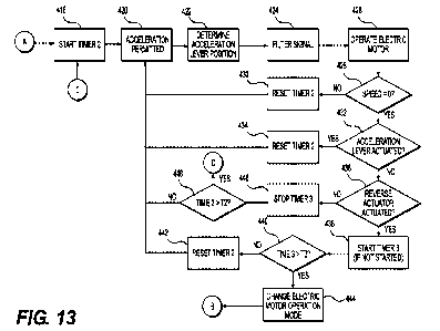
[001141 Turning now to Figs. 12 to 14, a method 400 for operating the
snowmobile 10 will
be described. It is contemplated that the method 400 could be used in other
types of electric
vehicles such as, but not limited to, straddle-type electric all-terrain
vehicles (ATVs) and
electric motorcycles. Some of these other types of electric vehicles may be
provided with an
5 acceleration pedal or an acceleration twist grip instead of the
acceleration lever 140. The
method 400 will be described with reference to the acceleration lever 140, but
it should be
understood that other kinds of acceleration input devices could be used.
[00115] The method 400 starts at 402 when the start actuator 402, in this case
the start button
138, is actuated. It is contemplated that in some embodiments, prior to step
402, at least some
10 of the systems of the snowmobile 10 have been turned on when the key 190
is received in the
key receiver 188 and the key 190 is recognized by the VCU 176. It is
contemplated that in
other embodiments, at least some of the systems are turned on once the start
actuator 402 is
actuated, and the method 400 only proceeds when the key 190 is received in the
key receiver
188 and the key 190 is recognized by the VCU 176.
15 [001161 From step 402, at step 404 the VCU 176 starts a timer (Timer 1).
Then, at step 406,
the VCU 176 determines, based on the timer (Timer 1), if the time (Time 1)
elapsed since the
timer (Timer 1) has been started at step 404 has reached a predetermined
amount of time Ti.
In one embodiment, the time Ti is 500 milliseconds, but other times are
contemplated. If the
time (Time 1) has not reached the predetermined amount of time Ti, the VCU 176
continues
20 to monitor the time (Time 1) until the predetermined amount of time Ti
has been reached.
Once the predetermined amount of time Ti has been reached, the VCU 176
proceeds to step
408.
[00117] At step 408, the VCU 176 determines if a speed is equal to zero which
is indicative
of the snowmobile 10 being at rest. In one embodiment, the speed is the speed
of the
25 snowmobile 10 as detennined by the vehicle speed sensor 179. In another
embodiment, the
speed is the speed of the electric motor 32 as determined from the motor speed
sensor 177. It
is contemplated that the motor speed sensor 177 could not sense the speed of
the electric motor
32 directly. For example, the motor speed sensor 177 could sense a speed of
rotation of the
drive axle 96, and the speed of rotation of the electric motor 32 can be
determined since the
30 drive ratio between the electric motor 32 and the drive axle 96 is
fixed. It is contemplated that
in some embodiments, at step 408 the VCU 176 could determine if both the speed
of the
snowmobile 10 and the speed of the electric motor 32 are zero for redundancy.
CA 03156771 2022-4-29
WO 2021/084520
PCT/1B2020/060274
[00118] If at step 408 the speed is not zero, the VCU 176 continues to monitor
the speed until
the speed is determined to be zero.
[00119] If at step 408 the speed is zero (i.e. the snowmobile 10 is at rest),
then at step 410
the VCU 176 determines if the acceleration lever 140 is actuated based on a
signal from the
5 acceleration lever position sensor 181. If the acceleration lever 140 is
actuated, then the VCU
returns to step 408 and continues to monitor the speed (step 408) and the
position of the
acceleration lever 140 (step 410) until the speed is zero and the acceleration
lever 140 is not
actuated. It is contemplated that if the speed and the acceleration lever
position 140 have been
monitored for more than a predetermined amount of time, an indication of an
error could be
10 provided to the driver of the snowmobile 10, such as a visual indication
on the display cluster
68 and/or by generating a noise. If at step 410 the VCU 176 determines that
the acceleration
lever 140 is not actuated, then at step 412 the VCU 176 considers that the
start sequence has
been completed. It is contemplated that at step 412 an indication that the
start sequence has
been completed could be provided to the driver of the snowmobile 10, such as a
visual
15 indication on the display cluster 68 and/or by generating a noise. Then
at step 414 the VCU
176 stops the timer (Timer 1). It is contemplated that the order of steps 408
and 410 could be
reversed. It is also contemplated that the order to steps 412 and 414 could be
reversed.
[001201 From step 414, the VCU 176 proceeds to step 416 where the VCU 176
sends a signal
to the BCU 174 to enable the requested operation mode of the electric motor
32. When the
20 snowmobile 10 is first started (i.e. the first time step 416 is
performed), the requested operation
mode is a forward mode (i.e. the electric motor 32 should be turned in a
direction that will
make the snowmobile 10 move forward). As will be indicated below, the
operation mode can
be changed to a reverse mode (i.e. the electric motor 32 should be turned in a
direction that will
make the snowmobile 10 move forward)
25 [00121] From step 416, the VCU 176 proceeds to step 418 (Fig. 13) and
starts a timer (Timer
2). The VCU 176 then proceeds to step 420 and enables operation of the
electric motor 32 by
permitting acceleration. Prior to step 420, actuating the acceleration lever
140 would not result
in the operation of the electric motor 32. As would be understood from steps
408 and 410, the
operation of the electric motor 32 will not be enabled at step 420 unless the
speed is zero and
30 the acceleration lever 140 is not actuated at steps 408 and 410.
CA 03156771 2022-4-29
WO 2021/084520
PCT/1B2020/060274
26
[001221 Then at step 422, the VCU 176 determines the position of the
acceleration lever 140
based on a signal from the acceleration lever position sensor 181. Then at
step 424, the VCU
176 uses a signal filter to filter the signal from the acceleration lever
position sensor 181 to
obtain a filtered signal. In the present embodiment, the signal from the
acceleration lever
5 position sensor 181 is filtered using a digital filter to enable
filtering of unintended variations
in the position of the acceleration lever 140. More specifically, the digital
filter enables control
of unintended signal activation by way of a controlled disconnect between the
true position of
the acceleration lever 140 and normal response of the electric motor 32. It is
contemplated that
other kinds of signal filters to could be used. It is contemplated that other
steps described in
10 the present application which determine the position of the acceleration
lever 140 could be
followed by a filtering step similar to step 424.
[0012.31 From step 424, the VCU 176 proceeds to step 426. At step 426, the VCU
176 and
the BCU 174 operate the electric motor 32 based at least in part on the
filtered signal of step
424 indicative of the position of the acceleration lever 140 and the operation
mode enabled at
15 step 416.
[00124] From step 426, the VCU 426 proceeds to step 428. At step 428, the VCU
176
determines if a speed is equal to zero which is indicative of the snowmobile
10 being at rest.
In one embodiment, the speed is the speed of the snowmobile 10 as determined
by the vehicle
speed sensor 179. In another embodiment, the speed is the speed of the
electric motor 32 as
20 determined from the motor speed sensor 177. It is contemplated that in
some embodiments, at
step 428 the VCU 176 could determine if both the speed of the snowmobile 10
and the speed
of the electric motor 32 are zero for redundancy.
[00125] If at step 428 the speed is not zero, the VCU 176 proceeds to step 430
and resets the
timer (Timer 2). From step 430, the VCU 176 returns to step 420.
25 [00126] If at step 428 the speed is zero (i.e. the snowmobile 10 is at
rest), then at step 432
the VCU 176 determines if the acceleration lever 140 is actuated based on a
signal from the
acceleration lever position sensor 181. If the acceleration lever 140 is
actuated, then the VCU
176 proceeds to step 434 and resets the timer (Timer 2). From step 434, the
VCU 176 returns
to step 420.
30 [00127] If at step 432 the VCU 176 determines that the acceleration
lever 140 is not actuated,
then at step 436 the VCU 176 determines if the reverse actuator, in this
embodiment the reverse
CA 03156771 2022-4-29
WO 2021/084520
PCT/1132020/060274
27
button 138, is actuated. If the reverse button 138 is actuated, then at step
438 the VCU 176
starts a timer (Timer 3) if the timer has not been started or is stopped. Then
at step 440, the
VCU 176 determines, based on the timer (Timer 3), if the time (Time 3) elapsed
since the timer
(Timer 3) has been started at step 438 has reached a predetermined amount of
time T3. In one
5 embodiment, the time T3 is 2 seconds, but other times are contemplated.
If the time (Time 3)
has not reached the predetermined amount of time 113, the VCU 176 proceeds to
step 442 and
resets the timer (Timer 2). From step 442, the VCU 176 returns to step 420. If
at step 440 the
predetermined amount of time T3 has been reached, the VCU 176 proceeds to step
444.
[00128] At step 444, in response to the reverse button 138 being actuated
without interruption
10 for the predetermined amount of time 13, the VCU 176 sends a signal to
the BCU 174 to
change the operation mode of the electric motor 32. If at step 444 the
operation mode was the
forward mode prior to the reverse button 138 being actuated at step 436, the
operation mode is
changed to the reverse mode. If at step 444 the operation mode was the reverse
mode prior to
the reverse button 138 being actuated at step 436, the operation mode is
changed to the forward
15 mode. It is contemplated that at step 444 an indication that the
operation mode has been
changed could be provided to the driver of the snowmobile 10, such as a visual
indication on
the display cluster 68 and/or by generating a noise. It is contemplated that
the indication to the
driver could be different depending on the one of the forward mode and the
reverse mode that
is now the operation mode of the electric motor 32. From step 444, the VCU 176
proceeds to
20 step 416 (Figure 12).
[00129] If at step 436, the reverse button 138 is not actuated, then at step
446 the VCIJ 176
stops and resets the timer (Timer 3). Then at step 448, the VCU 176
determines, based on the
timer (Timer 2), if the time (Time 2) has reached a predetermined amount of
time T2. The
predetermined amount of time 112 is greater than the predetermined amount of
time Ti In one
25 embodiment, the time 112 is 5 minutes, but other times are contemplated.
If the time (Time 2)
has not reached the predetermined amount of time T2, the VCU 176 returns to
step 420. hat
step 448 the predetermined amount of time Ti has been reached, the VCU 176
proceeds to step
450 (Fig. 14).
[00130] At step 450, the VCU 176 enters an idle mode. Upon entering the idle
mode,
30 acceleration is no longer permitted and actuating the acceleration lever
140 does not operate
the electric motor 32. In the idle mode, the batteries 152, 154 and other
electrical and electronic
components remain turned on. As would be understood from steps 428, 432,436
and 448, the
CA 03156771 2022-4-29
WO 2021/084520
PCT/lE2020/060274
28
VCU 176 will not enter the idle mode at step 450 unless the speed is zero, the
acceleration
lever 140 is not actuated, and the reverse button 38 is not actuated at steps
428, 432 and 436
for the predetermined amount of time T2 (step 448). It is contemplated that at
step 450 an
indication that the idle mode has been entered could be provided to the driver
of the
5 snowmobile 10, such as a visual indication on the display cluster 68
and/or by generating a
noise.
[00131] From step 450, at step 452 the VCU 176 determines if the start button
138 is
actuated. If at step 452 the start button 138 returns to step 450 and stays in
the idle mode. If
at step 452 the start button 138 is actuated, the VCU 176 proceeds to step
454.
10 [001321 At step 454, the VCU 176 determines if a speed is equal to zero
which is indicative
of the snowmobile 10 being at rest In one embodiment, the speed is the speed
of the
snowmobile 10 as determined by the vehicle speed sensor 179. In another
embodiment, the
speed is the speed of the electric motor 32 as determined from the motor speed
sensor 177. It
is contemplated that in some embodiments, at step 408 the VCU 176 could
determine if both
15 the speed of the snowmobile 10 and the speed of the electric motor 32
are zero for redundancy.
[001331 If at step 454 the speed is not zero, the VCU 176 returns to step 452.
[001341 If at step 454 the speed is zero (i.e. the snowmobile 10 is at rest),
then at step 456
the VCU 176 determines if the acceleration lever 140 is actuated based on a
signal from the
acceleration lever position sensor 181. If the acceleration lever 140 is
actuated, then the VCU
20 returns to step 452. It is contemplated that if the speed and the
acceleration lever position 140
have been monitored for more than a predetermined amount of time, an
indication of an error
could be provided to the driver of the snowmobile 10, such as a visual
indication on the display
cluster 68 and/or by generating a noise. If at step 456 the VCU 176 determines
that the
acceleration lever 140 is not actuated, then the VCU 176 returns to step 418
(Fig. 13) to start
25 and reset the timer (Timer 2) again. It is contemplated that the order
of steps 452 and 454 could
be reversed.
[001351 Turning now to Fig. 15, a program execution sequence 500 of the method
400 of
Figs 12 to 14 will be described. While the method 400 is being performed (i.e.
the various
systems of the snowmobile 10 are powered-up (step 502)), according to the
program execution
30 sequence 500, for each of the applications that have to be executed by
the VCU 176 and the
BCU 174, the inputs of the applications are updated (step 504), then the
applications are
CA 03156771 2022-4-29
WO 2021/084520
PCT/1132020/060274
29
executed (step 506), and then the outputs are updated (step 508). The at step
510, the VCU
176 determines if the motor cut-off switch has been activated or if the
security system key 190
has been disconnected from the key receiver 188. If not, then the VCU returns
to step 504. If
at step 510, the motor cut-off switch has been activated or the security
system key 190 has been
5 disconnected from the key receiver 188, then at step 512, the VCU 176
initiates a shutdown
sequence. The shutdown sequence includes stopping the operation of the
electric motor 32 and
stopping the supply of power from the batteries 152, 154. As such, according
to the program
execution sequence, should the motor cut-off switch be activated or the
security system key
190 be disconnected from the key receiver 188 at any time during the
performance of the
10 method 400, the VCU 176 will initiate the shutdown sequence 512, but
only once the outputs
of the application that are being executed (step 506) have been updated (step
508). It is
contemplated other program execution sequences could be used.
[001361 Modifications and improvements to the above-described embodiments of
the present
technology may become apparent to those skilled in the art. The foregoing
description is
15 intended to be exemplary rather than limiting. The scope of the present
technology is therefore
intended to be limited solely by the scope of the appended claims.
CA 03156771 2022-4-29