Note: Descriptions are shown in the official language in which they were submitted.
WO 2021/096836
PCT/US2020/059797
SYSTEMS AND METHODS FOR HARVESTING VIBRATION ENERGY USING
A HYBRID DEVICE
Background
[0001] Field of the invention.
[0002] The invention relates generally to energy generation, and more
particularly to systems
and methods for generating electrical energy from vibrations using a self-
contained
apparatus that employs multiple energy conversion mechanisms that are
effective in
different frequency ranges.
[0003] Related art.
[0004] Wireless devices for sensing and communication have become very popular
in
industrial environments for a number of reasons. For example, sensors are
conventionally connected to electronic devices (e.g., monitors, controllers,
etc.) by
wires that carry signals from the sensors to the corresponding devices. While
this may
not necessarily be impractical for a few sensors, it may be necessary or
desirable in
some systems to have hundreds, or even thousands of sensors measuring various
conditions or characteristics, such as pressure, temperature and vibration
levels or
machines or process materials. If each of the sensors has a corresponding
wired
connection, there will be hundreds or thousands of wires, which will increase
the size,
weight, cost and complexity of the system. Additionally, the sensors may be
located in
hazardous environments, so it may be desirable to avoid having wires or cables
that
would be exposed to the hazardous environment, or which would potentially
expose
the environment to electrical energy.
[0005] It is therefore often advantageous to use wireless systems for sensing
and
communication of sensor data. Wireless systems, however, require a local
energy
source to provide power for the sensors and related communication devices.
Typically,
these wireless systems use batteries, but batteries have a limited lifetime
and after
-1-
CA 03156898 2022-5-2
WO 2021/096836
PCT/US2020/059797
their energy is expended, the batteries must be replaced. Frequently, the
conditions
that make it advantageous to use a wireless device also make it difficult to
replace the
batteries for these devices. For example, when a wireless sensor is used in a
hazardous environment, the process of replacing the battery for the sensor may
involve
taking the sensor out of service, venting the area in which the sensor is
installed,
removing the sensor to a safe area, replacing the sensors battery, and
reinstalling the
sensor. This process may be inconvenient, tedious, time-consuming and
expensive.
When many wireless sensors are used, these problems are multiplied, as the
process
for replacing the batteries must be carried out for many devices.
[0006] Various alternative energy sources have been used in place of
batteries. For instance,
some applications allow for the use of solar cells that harvest radiated
energy from the
sun and convert this energy to electricity. The effectiveness of solar CELLS
depends
on a number of factors, such as exposure of the solar cells to sunlight, the
positioning
of the solar cells, and the angle of the solar cells with respect to the
impinging sunlight.
These factors may change as the sun changes positions in the sky.
Additionally, since
solar cells generally require exposure to sunlight, it is often necessary to
mount the
solar cells on the roof of a building and then connect the solar cells to the
sensors or
other devices which require power, which to some extent defeats the purpose of
using
the wireless devices.
[0007] In other systems, energy harvesters have been devised to convert
vibrational energy to
electrical energy. These devices typically are not integral to the wireless
sensor or
device, and are not available in a package that can be conveniently installed
in such a
device. Often, vibration energy harvesters are manufactured as a standalone
device
that has to be mounted exterior to a piece of equipment (e.g., on the surface
of an
engine case) with a cable running from the energy harvester to the sensor.
Energy
harvesters that are to be mounted on a device already in the field are
commonly
required to be mounted separately from the device and electrically connected
to the
device by power cables or wires. The efficiency of conventional vibrational
energy
harvesters is commonly very much dependent on the specific vibration
environment in
which they are used, as they are typically tuned to a specific (e.g.,
resident) frequency
of vibration and are not able to generate significant amounts of electrical
energy from
vibrations at frequencies which differ substantially from the tuned frequency.
-2-
CA 03156898 2022-5-2
WO 2021/096836
PCT/US2020/059797
[0008] Other systems may use devices that are configured to harvest thermal
energy, and to
convert this energy to electrical energy for use by a wireless sensor or other
device.
These thermal energy harvesting devices have varying efficiencies, depending
upon
factors such as, for example, the temperature of the environment and the
temperature
of the device on which it is mounted (e.g., an engine). Still other types of
energy
harvesting devices may also be used. Each of these devices has its own
benefits and
disadvantages.
[0009] It would be desirable to provide energy harvesting devices that reduce
or eliminate one
or more of the disadvantages of these conventional devices.
-3-
CA 03156898 2022-5-2
WO 2021/096836
PCT/US2020/059797
Summary
[0010] This disclosure is directed to systems and methods for generating
electrical energy
from vibrational energy that reduce or eliminate one or more of the problems
above.
Generally, these systems and methods involve providing hybrid energy
harvesting
mechanisms in a conventional form factor to facilitate their use in devices
designed to
use conventional batteries for power.
[0011] Embodiments of the present invention harvest vibrational energy over a
broader
frequency spectrum than prior art devices by employing several different
energy
harvesting mechanisms to generate electrical energy. In an exemplary
embodiment, an
energy harvesting device uses an inductive current generator to convert
vibrational
energy at lower frequencies to electrical energy, and also uses one or more
piezoelectric charge generators to convert vibrational energy at higher
frequencies to
electrical energy. The electrical energy produced by these different
harvesting
mechanisms is provided to a controller which processes the input energy and
generates an output which is applied to an energy store such as a battery. The
energy
stored in the battery can then be drawn as needed by an electrical device such
as a
wireless sensor or transmitter. The energy harvesting device may be configured
as a
package that has the same form factor as a conventional battery (e.g., a 0-
cell battery)
which may be conveniently used in equipment that is adapted to use this
conventional
battery without having to modify the equipment to use the energy harvesting
device.
[0012] One embodiment comprises an energy harvesting apparatus having first
and second
electrical generators configured to generate electrical energy from vibrations
in a first
and second frequency ranges, respectively, an energy store such as a
rechargeable
battery or supercapacitor, and an electrical controller. The electrical
generators are
configured to provide generated electrical energy to the electrical controller
which
includes a processor circuit configured to generate output power. This output
power is
provided to the energy store, thereby charging the energy store. The energy
harvesting apparatus is coupled to a device such as a wireless sensor or
transceiver,
which draws energy from the energy store to operate the device.
-4-
CA 03156898 2022-5-2
WO 2021/096836
PCT/US2020/059797
[0013] In one embodiment, the first electrical generator comprises an
inductive current
generator having a magnet and a coil, where movement of the coil with respect
to the
magnet induces current in the coil. The magnet is held in a substantially
stationary
position within a housing of the energy harvesting apparatus. The coil is
positioned
within the housing of the energy harvesting apparatus and is electrically
coupled to the
electrical controller. The coil is movable with respect to the magnet (in
response to
vibrations experienced by the apparatus), where movement of the coil with
respect to
the magnet induces current in the coil which is provided to the controller. In
one
embodiment, the magnet of the energy harvesting apparatus has a cylindrical
shape,
and the coil is wound on a cylindrical support that is coaxially positioned
around the
magnet. The cylindrical support is connected in this embodiment to a frame of
the
apparatus by one or more springs, and is axially movable with respect to the
magnet in
response to the vibrations experienced by the apparatus. The apparatus may
also
have a magnetically permeable cylinder coaxially positioned around the
cylindrical
support, the magnetically permeable cylinder being positioned in fixed
relation to the
magnet.
[0014] In one embodiment, the second electrical generator of the energy
harvesting apparatus
is a piezoelectric charge generator having one or more piezoelectric plates.
The
magnet in this embodiment provides a proof mass which is positioned to apply
pressure to the one or more piezoelectric plates when the magnet experiences
vibrations. The piezoelectric plates are electrically coupled to provide
charge generated
by the plates to the electrical controller. The piezoelectric plates may
include a first set
of plates that generate charge responsive to vibrations within the second
frequency
range of frequencies, and a second set of plates that generate charge
responsive to
vibrations within a third frequency range. The apparatus may also include one
or more
conductive spacers positioned between the piezoelectric plates.
[0015] In one embodiment, the energy harvesting apparatus includes a housing
that contains
the first electrical generator, the second electrical generator, the energy
store, and the
electrical controller. A positive electrical contact for the energy store is
provided at a
first end of the housing and a negative electrical contact for the energy
store is
provided at a second end of the housing opposite the first end of the housing.
The
housing may have a form factor of a conventional battery, such as a C cell
battery or a
D cell battery. This facilitates installation of the energy harvesting
apparatus in a
-5-
CA 03156898 2022-5-2
WO 2021/096836
PCT/US2020/059797
battery compartment of a wireless sensor or other device, which may be mounted
on a
motor or other vibrating device to receive the vibrations from the device.
[0016] Numerous other embodiments may also be possible.
-6-
CA 03156898 2022-5-2
WO 2021/096836
PCT/US2020/059797
Brief Description of the Drawings
[0017] Other objects and advantages of the invention may become apparent upon
reading the
following detailed description and upon reference to the accompanying
drawings.
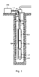
[0018] FIGURE 1 is a diagram illustrating an exemplary implementation of an
energy
harvesting device in an ESP system in accordance with some embodiments.
[0019] FIGURE 2 is a diagram illustrating the general structure of a system
using an energy
harvesting device to power a wireless sensor/transmitter in accordance with
some
embodiments.
[0020] FIGURE 3 is a diagram illustrating the general structure of an energy
harvesting device
in accordance some embodiments.
[0021] FIGURE 4 is a diagram illustrating the detailed structure of an
exemplary energy
harvesting device in accordance with some embodiments.
[0022] While the invention is subject to various modifications and alternative
forms, specific
embodiments thereof are shown by way of example in the drawings and the
accompanying detailed description. It should be understood, however, that the
drawings and detailed description are not intended to limit the invention to
the
particular embodiment which is described. This disclosure is instead intended
to cover
all modifications, equivalents and alternatives falling within the scope of
the present
invention as defined by the appended claims.
-7-
CA 03156898 2022-5-2
WO 2021/096836
PCT/US2020/059797
Detailed Description of Exemplary Embodiments
[0023] One or more embodiments of the invention are described below. It should
be noted
that these and any other embodiments described below are exemplary and are
intended to be illustrative of the invention rather than limiting.
[0024] As described herein, various embodiments of the invention comprise
systems and
methods for harvesting vibrational energy in multiple frequency ranges using a
combination of harvesting mechanisms and converting the harvested vibrational
energy to electrical energy which is stored for use by an electrical device.
[0025] In an exemplary embodiment, a hybrid energy harvesting device is
installed in a
wireless sensor which is coupled to a motor, such as the motor of an electric
submersible pump (ESP). It should be noted that in other embodiments, energy
harvesting devices may be installed in other types of devices that are coupled
to other
types of equipment in which the energy harvesting device will be subject to
vibration.
[0026] The energy harvesting device includes two different types of electrical
energy
generators: an inductive current generator; and piezoelectric charge generator
The
Inductive current generator includes a stationary permanent magnet and one or
more
coils of magnet wire that are installed on a movable, spring-mounted support
structure
(collectively referred to as the coil structure). In this embodiment, the
magnet and the
coil structure are both generally cylindrical, with the coil structure being
positioned
coaxially around the magnet. As the device experiences vibrations, the
vibrations
cause the coil structure to move up and down in an axial direction, with the
wires of the
coils passing through the flux lines of the magnet and thereby inducing
currents in the
coils.
[0027] The second type of electrical energy generator is the piezoelectric
charge generator
The piezoelectric charge generator includes a set of discs made of a
piezoelectric
material. These discs are positioned on opposite ends of the permanent magnet,
with a
conductive material separating each of the discs. The permanent magnet serves
as
the conductive material between two of the piezoelectric discs. This stack
further
includes a pair of conductive discs at opposing ends of the stack which hold
the stack
-8-
CA 03156898 2022-5-2
WO 2021/096836
PCT/US2020/059797
in a substantially fixed position. As the device experiences vibrations, the
vibrations
cause the magnet to apply pressure to the piezoelectric discs, thereby causing
the
discs to produce electrical charge.
[0028] The piezoelectric discs and the coils are electrically connected to
power processing
and management circuitry (which may be referred to herein simply as a
controller)
which processes the charge generated by the piezoelectric discs and the
electrical
current generated by the coils. The controller uses the generated charge and
current to
generate an electrical potential that is applied to a battery which is
incorporated into the
energy harvesting device. This potential charges the battery, which can then
be used
as an energy source to drive the wireless sensor or other electrical device in
which it is
installed.
[0029] In some embodiments, the energy harvesting device is integrated into a
package that
has the same form factor (i.e., external configuration, such as size and
shape) as a
conventional battery. For example, the energy harvesting device may be the
same
size and shape as a D-cell battery, with a positive electrical contact at one
end and a
negative electrical contact at the other end. Since wireless devices are
commonly
designed to be powered by conventional batteries, providing the energy
harvesting
device in this type of package allows the device to be installed in many
wireless
devices in the same way a conventional battery is installed in a battery
compartment of
the wireless device, thereby eliminating the need to modify the designs of
either the
wireless devices or the energy harvesting device to allow the energy
harvesting device
to be incorporated into the wireless device.
[0030] Referring to FIGURE 1, a diagram illustrating an exemplary
implementation of an
energy harvesting device in an ESP system is shown. In this embodiment, an ESP
system is installed in a well for the purpose of producing hydrocarbons such
as oil, or
other fluids. The ESP 120 is coupled to the end of tubing string 150, and the
ESP and
tubing string are lowered into the wellbore to position the ESP in a producing
portion of
the well. Surface equipment which includes an electric drive system 110 is
positioned
at the surface of the well. Drive system 110 is coupled to ESP 120 by power
cable
112, which runs down the wellbore along tubing string 150.
-9-
CA 03156898 2022-5-2
WO 2021/096836
PCT/US2020/059797
[0031] In this embodiment, ESP 120 includes a motor section 1211 a seal
section 122, and a
pump section 123. ESP 120 also includes a gauge package 124 that includes an
energy harvesting device to provide power for one or more electronic
components such
as a wireless sensor and transmitter. Motor section 121 is coupled to power
cable 112,
and is driven by AC power (typically three-phase AC power) that is received
from drive
system 110 through the cable. Motor section 121 is coupled to pump section 123
through seal section 122 to drive the pump section, thereby pumping the oil or
other
fluid through the tubing string and out of the well. Seal section 122 is
provided
between motor section 121 and pump section 123 for purposes including
equalizing
the pressure between the motor interior and the well bore and allowing the oil
within
the motor to expand and contract.
[0032] In this embodiment, power for the electronic components of the gauge
package is
provided by an energy harvesting device that is configured to convert
vibrational
energy to electrical energy. The gauge package may include a sensor that is
configured to sense a condition such as temperature or pressure in the motor
or the
well environment. The sensor data may be provided to a transmitter that is
configured
to transmit the data to a receiver 116 at the surface of the well. Receiver
116 may then
communicate the received data to a monitor or other component of surface
equipment
110 via a wired interconnect 114.
[0033] It should be noted that the ESP system described here is merely an
illustrative
application for the disclosed energy harvesting devices. These devices may be
used in
connection with other downhole devices that are subject to vibrations, surface
equipment (including motors or other mechanical equipment), or any other
environments in which the devices are exposed to vibrational energy that may
be
converted to electrical energy. Additionally, the specific configurations of
the
generators described herein are illustrative, and alternative embodiments may
have
different form factors, different generator types and designs, different
numbers of
generator components, and so on.
[0034] Referring to FIGURE 2, a diagram illustrating the general structure of
a system using
an energy harvesting device to power a wireless sensor/transmitter in
accordance with
some embodiments is shown. This diagram depicts a more general implementation
of
the energy harvesting device. On the right side of the figure is a piece of
equipment
-10-
CA 03156898 2022-5-2
WO 2021/096836
PCT/US2020/059797
210 that is subject to vibration, either because the equipment itself vibrates
during
operation, or because it is exposed to vibration in the environment in which
it operates.
As noted above, an electric motor is an example of a piece of equipment that
generates vibrations as it operates.
[0035] A wireless sensor system 220 is coupled to equipment 210. The wireless
sensor
system may be incorporated into the design of equipment 210, or it may be
externally
coupled to the equipment. For example, a standalone wireless sensor unit may
be
secured to a housing of equipment 210. In either case, wireless sensor system
220 is
caused to vibrate, such as when equipment 210 is operated and generates
vibrations.
These vibrations are communicated to energy harvesting device 222, which is
secured
within the wireless sensor system. The vibrations are in turn communicated to
the
internal components within energy harvesting device 222, which convert the
vibrational
energy to electrical energy.
[0036] Energy harvesting device 222 is a hybrid device which includes multiple
electrical
energy generators that are operable within different ranges of frequencies.
The
electrical energy produced by each of the generators is processed by circuitry
within
the energy harvesting device which is configured to convert this energy to a
suitable
voltage for charging a battery, which is also contained within the energy
harvesting
device. In this example, wireless sensor system 220 includes a sensor
component 224
and a transmitter component 226. Each of these components is coupled to energy
harvesting device 222 so that they can draw power from the charged battery.
[0037] As depicted in FIGURE 2, equipment 210 and wireless sensor system 220
may be
located in an area (to the right of the dashed line in the figure) which is
inaccessible,
inconvenient or impractical to access. This area may be downhole in a well, in
a
location that contains hazardous gases, or another area which is difficult to
access.
Consequently, the components of the wireless sensor system (sensor 224 and
transmitter 226 in this embodiment) are powered by energy harvesting device
222, and
do not require a connection to an external power source. Sensor 224 draws
power
from the battery of energy harvesting device 222 to sense conditions related
to
equipment 210 or its environment. Transmitter 226, which also draws power from
the
battery of enemy harvesting device 222, receives data from sensor 224 and
wirelessly
communicates this data to a receiver 244 of monitoring unit 240. Receiver 244
may
-11-
CA 03156898 2022-5-2
WO 2021/096836
PCT/US2020/059797
then provide the data to monitoring circuitry 242 within the unit. In this
example,
monitoring unit 240 is located in an area (e.g., the surface of a well) which
is not
inaccessible / inconvenient / impractical to access, so it may be
conventionally
powered (i.e. may draw power from a power grid, generator, battery, or other
conventional means).
[0038] Referring to FIGURE 3, a diagram illustrating the general structure of
an energy
harvesting device in accordance with some embodiments is shown. In this
embodiment, energy harvesting device 222 includes multiple energy generators
(310a,
310b, ...) which are configured to convert vibrational energy into electrical
energy.
Each of the energy generators is designed to be effective in a different range
of
frequencies so that the device can more effectively convert vibrational energy
into
electrical energy, as compared to conventional vibrational energy harvesting
devices
which are typically designed for particular applications and which are tuned
to convert
vibrations within a relatively narrow band of frequencies (e.g., around the
running
frequency of the equipment on which it is mounted). In one embodiment, a first
one of
the generators uses an induction mechanism to convert vibrations at lower
frequencies
(e.g., up to a few hundred Hz) to electrical current, while a second one of
the
generators uses a piezoelectric mechanism to convert vibrations at higher
frequencies
(e.g., several hundreds of Hz to several thousands of Hz). Other electrical
generators
within the energy harvesting device may be configured to use the same or
different
energy conversion mechanisms, and may be responsive to vibrations in various
frequency ranges (which may be the same, different, or overlapping to various
degrees).
[0039] Each of electrical energy generators 310 is connected to a controller
or power
management circuit 320. Controller 320 is designed to receive the outputs of
the
different generators and to convert the received electrical energy to a form
which is
suitable to charge an energy store 330, which may be a rechargeable battery,
supercapacitor ("supercap") or other type of energy storage device.
(References herein
to a battery in the energy harvesting device should be broadly construed to
include the
various different types of energy stores that may be available for use in the
device.)
Thus, controller 320 may include circuitry configured to convert varying AC
currents
generated by an induction-type generator to a DC voltage that is suitable for
charging
the battery, and may include separate circuitry configured to convert the
charge
-12-
CA 03156898 2022-5-2
WO 2021/096836
PCT/US2020/059797
generated by a piezoelectric-type generator to the DC voltage needed to charge
the
battery.
[0040] "Supercapacitor" or "supercap" is used herein to refer to a type of
high-capacity
capacitor which typically has a very high capacitance value and a relatively
low voltage
limit. Supercaps can therefore be used in a manner which is similar to a
rechargeable
battery.
[0041] Electrical energy generators 310, controller 320 and energy store 330
are packaged
within a housing 340. Housing 340 is a substantially rigid structure that has
the form of
a conventional battery. Wireless devices and other devices that require a
local/internal
source of power are commonly configured to use conventional C cell or D cell
batteries, so housing 340 may be designed to have the same size and shape as
one of
these battery types. This allows the energy harvesting device to be installed
in one of
these wireless or other battery-powered devices in the same manner as a
conventional
battery. By contrast, existing energy harvesting devices typically have form
factors
which are driven by the design of the energy harvesting mechanisms within the
devices. These devices may have many different package sizes and different
connectors. Therefore, in order to use these prior art energy harvesting
devices in a
wireless or other device, it is typically necessary to modify the wireless
device to
accommodate the particular package and connectors of the energy harvesting
devices.
[0042] Referring to FIGURE 4, a diagram illustrating the detailed structure of
an exemplary
energy harvesting device in accordance with one embodiment is shown in more
detail.
In this embodiment, exemplary energy harvesting device 400 includes three
different
mechanisms for converting vibrational energy to electrical energy: an
induction
mechanism effective in a first frequency range; a first piezoelectric
mechanism
effective in a second frequency range; and a second piezoelectric mechanism
which is
effective in a third frequency range. The induction mechanism uses one or more
coils
which are caused by vibrations to move within the fields of a perrnanent
magnet,
thereby inducing currents in the coils. These currents are provided to a power
management circuit which processes the currents and generates a DC voltage to
charge a rechargeable battery within the harvesting device. The first
piezoelectric
mechanism uses a set of high sensitivity piezoelectric ceramic discs in
conjunction with
the permanent magnet. Vibrations cause the permanent magnet to press against
the
-13-
CA 03156898 2022-5-2
WO 2021/096836
PCT/US2020/059797
piezoelectric discs, thereby causing them to generate charge which is provided
to the
power management circuit The power management circuit in turn uses the
generated
charge to produce a DC voltage for charging the battery. The second
piezoelectric
mechanism operates in the same manner as the first piezoelectric mechanism,
but the
piezoelectric discs are configured to generate charge more effectively in
response to
vibrations within a different frequency range than the first piezoelectric
mechanism.
[0043] As noted above, the inductive current generator of energy harvesting
device 400
employs a stationary permanent magnet 402 and a moving coil structure 404.
Magnet
402 is generally cylindrical in shape, with a concentric hole therethrough.
The magnet
is held in position by the discs of the piezoelectric charge generator
components, as
will be discussed in more detail below. A steel cylinder 424 is positioned
coaxially
around coil structure 404 and is secured to electrically conductive frame 412
so that it
is stationary_ Cylinder 424 is magnetically permeable, so it causes the
magnetic flux of
magnet 402 to be more concentrated in the area adjacent to coils 408.
[0044] Coil structure 404 consists of a generally tubular cylindrical coil
support structure 406
on which a set of coils 408 are wound. In this embodiment, two coils are wound
on
support structure 406 and connected to controller 416 to double the induced
voltage of
the coils. Coils 408 are connected via corresponding electrical leads 414 to
an
electrical controller 416 which includes power management circuitry. Leads 414
are
electrically isolated from frame 412 by insulators 418. Controller 416 may
itself be
isolated from the frame by insulator 420. Insulators 418 and 420 may be formed
using
glass, epoxy, or any other suitable insulating material.
[0045] Coil structure 404 is movable axially (up and down in the figure) with
respect to magnet
402. Coil structure 404 is connected by a set of spiral springs 410a-410d to a
frame
412 so that the coil structure will oscillate axially when device 400
experiences
vibrations. As coil structure 404 moves with respect to magnet 402, coils 408
cut
through the magnetic flux lines of the magnet, which induces current in the
coils. This
current is applied to the corresponding inputs of controller 416, and is
processed by the
controllers power management circuitry. Controller 416 processes the current
and
uses the received electrical energy to generate a desired DC voltage, which is
typically
higher than the voltage of the received energy. The DC voltage generated by
controller
416 is applied to energy store 422 which stores the received electrical
energy. Energy
-14-
CA 03156898 2022-5-2
WO 2021/096836
PCT/US2020/059797
store 422 may be a rechargeable battery, supercapacitor, or any other suitable
means
to store the electrical energy.
[0046] The piezoelectric current generators of energy harvesting device 400
employ high
sensitivity piezoelectric ceramic discs to generate charge from vibrations
experienced
by the device. In this embodiment, the energy harvesting device has four
annular
piezoelectric discs 426. The piezoelectric discs are stacked together with a
set of
annular conductive discs. A metal support disc 428 is positioned at the bottom
of the
stack_ Piezoelectric disc 426a is positioned on top of support disc 428, an
electrically
conductive spacer 430a is positioned on top of disc 426a, and piezoelectric
disc 426b
is positioned on top of spacer 430a. Permanent magnet 402 is positioned above
disc
426b, followed by piezoelectric disc 426c, electrically conductive spacer
430b,
piezoelectric disc 426d, and upper conductive spacer 432. Finally, an
electrically
insulating spacer 434 is positioned between conductive spacer 432 and frame
412.
Conductive cap 438 holds this stack against the upper part of frame 412, and
is
secured by bolt 436. There may be a gap between bolt 436 and the discs (and
magnet)
in the stack, or an insulator may be provided between the bolt and the discs
to prevent
the bolt from shorting the discs to frame 412.
[0047] Although the stack of piezoelectric and conductive discs and magnet 402
are held in
nominally fixed positions, vibrations experienced by the energy harvesting
device
cause the magnet to move very slightly up or down, serving as a proof mass
that
applies pressure to the piezoelectric discs in the stack. Bolt 436 has been
tightened to
preload cap 438 and thereby apply a base amount of pressure to the stack.
Consequently, when the device moves and magnet 402 presses upward or downward,
it causes the piezoelectric discs to be slightly more or less compressed,
thereby
generating charge.
[0048] For example, when the device moves upward, the magnet presses downward,
increasing the compression of piezoelectric discs 426a and 426b, and
decreasing the
compression of piezoelectric discs 426c and 426d. Piezoelectric discs 426a and
426b
are arranged so that this compression causes positive charge to be generated
by these
discs at the bottom of the stack. At the same time, the decompression of
piezoelectric
discs 426c and 426d causes negative charge to be generated by these discs at
the top
of the stack. Because the piezoelectric discs are separated by conductive
spacers
-15-
CA 03156898 2022-5-2
WO 2021/096836
PCT/US2020/059797
(including discs 428, 430, 432 and magnet 402), the piezoelectric discs are
effectively
connected in series electrically, and the charge is conducted through the
stack. Thus,
an electrical potential is developed across the stack (with positive potential
at the
bottom of the stack and negative potential at the top). Conversely, when the
device
moves downward, the magnet presses upward, decreasing the compression of
piezoelectric discs 426a and 426b, and increasing the compression of discs
426c and
426d. In this case, discs 426a and 426b generate negative at the bottom of the
stack,
and discs 426c and 426d generate positive charge at the top of the stack.
Thus, an
electrical potential with the opposite polarity is developed across the stack.
Consequently, as the device vibrates up and down, alternating positive and
negative
voltages are developed across the stack, and AC power is provided to
controller 416.
[0049] The AC power is communicated to controller 416 through leads 414.
Although only two
leads are shown in the figure for purposes of clarity, the number of leads
will depend
upon the specific configuration of the device. In one embodiment, three leads
are
provided_ Two of the leads connect coils 408 to controller 416, and one lead
connects
the stack including piezoelectric discs 426 to the controller. (Because
conductive
frame 412 is in contact with the lower end of the stack through conductive cap
438, it is
sufficient in this embodiment to connect only the upper end of the stack
through a lead
414.) The received charge is processed by the power management circuitry of
controller 416, which generates a DC output voltage that is applied to energy
store 422
to recharge the energy store.
[0050] As noted above, the piezoelectric discs effectively form two different
charge generators
that are operative in different frequency ranges. In the embodiment of FIGURE
4, there
are two piezoelectric discs corresponding to each generator. In alternative
embodiments, each piezoelectric generator may have more or fewer discs, and
the
discs may be alternatively positioned within the stack.
[0051] The first g piezoelectric generator uses the two discs at the upper end
of the stack and
the second generator uses the two discs at the lower end of the stack. In this
embodiment, the discs at the upper end of the stack are held between magnet
402,
which supports the entire horizontal extent of piezoelectric disc 426c, and an
upper
conductive spacer 432, where a portion of the horizontal extent of spacer 432
is held
against insulating spacer 434. The frequency range in which the first
piezoelectric
-16-
CA 03156898 2022-5-2
WO 2021/096836
PCT/US2020/059797
generator is effective can be altered by changing the portion of conductive
spacer 432
that is held against insulating spacer 434. By changing the resonant
frequency, the
frequency range in which the generator is effective is also changed. This can
be used
to tune the frequency response of the generator.
[0052] The second piezoelectric generator in this embodiment uses the two
piezoelectric discs
426a and 426b at the bottom of the stack. These discs are held between magnet
402,
which contacts the entire horizontal extent of piezoelectric disc 426c, and a
lower
conductive support spacer 428, where a portion of the horizontal extent of
spacer 428
is held against conductive cap 438. The resonant frequency of the second
piezoelectric generator, and consequently the frequency range in which the
generator
is effective, can be altered by changing the portion of conductive support
spacer 428
that is held against cap 438.
[0053] The performance of the piezoelectric generators may also be affected by
the
characteristics of the piezoelectric discs themselves, such as the material
and
thickness of the discs. Because of the difficulties of using multiple
different
configurations for the piezoelectric discs (e.g., with respect to
manufacturing the discs
so that they have different characteristics), it may be impractical to
implement
frequency range variations in this manner.
[0054] The inductive current generator and piezoelectric charge generators of
the energy
harvesting device are contained within a rigid housing 440. Positive (442) and
negative
(444) contacts to energy store 422 are provided at the upper and lower ends of
the
housing, respectively. The housing and contacts have a form factor that is the
same as
a conventional battery. The form factor may be equivalent to a C cell, D cell,
or any
other type of conventional battery used in the industry. This form factor
allows the
energy harvesting device to be installed in a wireless sensor, transmitter, or
other
battery-operated device in place of a conventional battery without having to
modify the
device to accommodate the energy harvesting device. The energy harvesting
device
may therefore serve as a self-replenishing battery or a continuous energy
source that
does not run down and need to be replaced like conventional batteries when
installed
in a device in a vibration environment.
-17-
CA 03156898 2022-5-2
WO 2021/096836
PCT/US2020/059797
[0055] The energy harvesting device of FIGURE 4, as well as other embodiments
disclosed
herein are distinctive of conventional devices in various respects. For
example, these
devices incorporate a combination of multiple different types of generators
(e.g.,
inductive and piezoelectric generators, where prior art devices use a single
technology
to convert vibration energy to electrical energy. Additionally, the use of
multiple
generators in the disclosed embodiments enables the energy harvesting devices
to
convert vibrational energy in a wider range of frequencies than conventional
devices. In
one embodiment as disclosed in FIGURE 4, the induction current generator may
be
designed to operate optimally in a frequency range from 5-100 Hz while the
first
piezoelectric generator operates optimally from 100-1000 Hz and the second
piezoelectric generator operates optimally in the range from 200-2000 Hz,
resulting in
an overall effective range from 5-2000 Hz. Another advantage of the disclosed
embodiments is that a stationary magnet is used as the proof mass for the
piezoelectric generators, which provides a more robust configuration and
longer
service life, as compared to conventional induction generator designs which
use a
moving magnet as a proof mass. Another advantage of disclosed embodiments is
that
the configuration of the housing of the energy harvesting device in a form
factor
corresponding to a conventional battery enables broad and convenient use of
the
device as a replacement for a conventional battery, and does not require
modification
of the device in which it is installed.
[0056] As noted above, the embodiments described above are intended to be
illustrative, but
not limiting of the invention. Alternative embodiments may incorporate
different types of
electrical energy generators, different numbers of generators, different
numbers of
discs within piezoelectric generators different arrangements of components,
and so on.
Many variations will be apparent to those of skill in the art upon reading
this disdosure.
[0057] The benefits and advantages which may be provided by the present
invention have
been described above with regard to specific embodiments. These benefits and
advantages, and any elements or limitations that may cause them to occur or to
become more pronounced are not to be construed as critical, required, or
essential
features of any or all of the described embodiments. As used herein, the terms
"comprises," "comprising," or any other variations thereof, are intended to be
interpreted as non-exclusively including the elements or limitations which
follow those
terms. Accordingly, a system, method, or other embodiment that comprises a set
of
-18-
CA 03156898 2022-5-2
WO 2021/096836
PC17[182020/059797
elements is not limited to only those elements, and may include other elements
not
expressly listed or inherent to the described embodiment.
[0058] VVhile the present invention has been described with reference to
particular
embodiments, it should be understood that the embodiments are illustrative and
that
the scope of the invention is not limited to these embodiments. Many
variations,
modifications, additions and improvements to the embodiments described above
are
possible. It is contemplated that these variations, modifications, additions
and
improvements fall within the scope of the invention as detailed by the claims
of the
application.
-19-
CA 03156898 2022-5-2