Note: Descriptions are shown in the official language in which they were submitted.
WO 2021/097420
PCT/US2020/060721
TRACHCOLLAR SAFETY ALARM
Inventors:
Dorothy Owens
Darleen Sawyer
Cross-Reference to Related Applications
This application is a U.S. Non-Provisional Patent Application that claims
priority from
U.S. Provisional Patent Application No. 62/974,105, filed on November 14,
2019, the contents of
which are hereby fully incorporated by reference.
Field of the Embodiments
The field of the invention and its embodiments relate to a securing collar or
band, sensor
apparatus, and alarm assemblies with wireless communication technology. More
specifically,
field of the invention and its embodiments relate to the securing collar or
band, the sensor
apparatus, and the alarm assemblies with wireless communication technology
that secure a
tracheostomy tube to a patient's body, detect movement of the tracheostomy
tube, and that alert
medical personnel of the movement of the tracheostomy tube.
Background of the Embodiments
During or after medical procedures, tubes may be inserted into a patient to
deliver
materials, such as fluids or gasses. As an example, a tracheotomy can be
performed on patients
who suffer from facial trauma or tumors of the head and/or neck. A
tracheotomy, or
1
CA 03157200 2022-5-4
WO 2021/097420
PCT/US2020/060721
tracheostomy, is a surgical procedure which consists of making an incision on
the anterior aspect
of the neck and opening a direct airway through an incision in the trachea.
Tracheal tubes allow a
patient to breathe without using the patient's nose or mouth.
Specifically, a tracheostomy (or trach) tube is a curved tube that is inserted
into a
tracheostomy stoma. A commonly used tracheostomy tube consists of three parts:
outer cannula
with flange (neck plate), inner cannula, and an obturator. The outer cannula
holds the
tracheostomy open. A neck plate extends from the sides of the outer tube and
has holes to attach
cloth ties or Velcro strap around the neck. The inner cannula fits inside the
outer cannula and has
a locking feature to keep it from being coughed out. The obturator is used to
insert a
tracheostomy tube. More specifically, the obturator fits inside the tube to
provide a smooth
surface that guides the tracheostomy tube when it is being inserted.
However, at any time, the tracheal tube can become dislodged, removed, or
displaced
from the patient inadvertently by the caregiver or patient. Patients who have
undergone a
tracheostomy require the tracheal tube to be securely and comfortably attached
to their neck over
long periods of time. Inadvertent removal or displacement of such tubes can be
particularly
serious to the point that the patient no longer receives the material supplied
by the tube. More
specifically, removal of such tubes after a tracheotomy can prevent the
patient from receiving
adequate oxygen, which can lead to serious injury or death.
Thus, what is needed is an apparatus that makes medical tubes more secure and
reliable,
and therefore less vulnerable to dislodging. Also, what is needed is a method
or means to alert a
caregiver when a tube is dislodged so that quick and effective corrective
action can occur to
avoid any injury to the patient.
2
CA 03157200 2022-5-4
WO 2021/097420
PCT/US2020/060721
Review of related technology:
U.S. Patent No. 3,595,228 describes a portable alarm device. The portable
alarm device is
attached to interfitting coupling portions in a therapeutic apparatus, such
as, the metal or plastic
coupling portions between a respirator hose and tracheostomy tube. The device
includes
normally engaging electric contacts on the coupling portions which separate
with the coupling
portions to sense a break. One contact is connected to the patient's body, the
other contact
connected to a low-power electric pulse generating circuit for triggering an
electric switch, the
latter being adapted to activate the alarm element when the contacts
disconnect to alert hospital
personnel.
U.S. Patent No. 4,259,965 describes a skin electrode for connecting monitoring
equipment to the surface of the skin, which is separable into two assemblies:
a base assembly
adapted to be mounted to the surface of the skin and having a sensing element
and a terminal
assembly adapted to be releasably coupled with the base assembly and having a
lead for
connection to the monitoring equipment. The terminal assembly is provided with
a magnet while
the base assembly is provided with a ferromagnetic element, whereby the
releasable coupling
and electrical connection of the assemblies may be ensured by the action of
the magnet.
U.S. Patent No. 5,578,003 describes a safety device for blood-, wound
secretion- and
infusion supplying conduit that leads to a vessel inlet. The safety device
includes: a magnet
mountable on a conduit, a Reed-relay fixed substantially close to the magnet
on a skin of a
patient so that when a distance between the Reed-relay and the magnet
increases as a result of
moving away of the vessel input the Reed-relay is switched, and a device for
triggering alarm in
response to the switching of the Reed-relay.
3
CA 03157200 2022-5-4
WO 2021/097420
PCT/US2020/060721
U.S. Patent No. 6,105,577 describes a device for supporting and retaining a
tracheostomy
tube or an endotracheal tube of the type having a tube, including a flexible
support flange and an
inner cannula having a locking means which connects the inner cannula to the
tube. The device
includes a holder base having a uniquely shaped tube receiving opening
designed to securely
retain the tube therein and which includes at least one through-slot extending
outward from the
opening for receiving the locking means therethrough and preventing contact
between the
locking means of the inner cannula and the holder base. The device includes a
removable tab
which extends into the opening, a removable support strap for releasably
securing the holder to
the patient and an anchor strap for anchoring a circuit in place.
U.S. Patent No. 6,588,426 describes achieving unwanted separation of an inner
cannula
from an outer cannula in tracheostomy devices by installing a retaining ring
that prevents the
inner cannula from unwantingly being unlatched from the outer cannula. The
retaining ring
allows the air supply elbow to be separated which, in turn, permits the
sensory alarms to properly
sound when a disconnection of the air supply arises.
U.S. Patent No. 7,416,532 describes an alarm device that includes a
temperature sensor
placed in the tube of a trach tube and which is adapted to activate an audible
alarm when
predetermine low temperature has been detected.
U.S. Patent No. 7,874,999 describes an access needle for extracorporeal
therapy that is
equipped with a mount and a sleeve having a metal or magnetic component at its
distal end. The
mount includes a sensor for detecting when the distal end is pressed against
the mount. The
sensor is a hall-effect sensor or a proximity sensor. When therapy is begun,
the sleeve is rolled
up and urged against the mount, exposing the needle for use with the patient.
While the sleeve,
and the piece of metal or magnet, remains in contact with the sensor, the
needle has not been
4
CA 03157200 2022-5-4
WO 2021/097420
PCT/US2020/060721
dislodged and therapy may continue, If the needle is dislodged, the sleeve
pushes away from
mount, moving the metal or magnet away from the sensor. The sensor notes the
dislodgement
and sends a signal to alert the patient or a caregiver,
U.S. Patent No. 6,725,862 describes a measured suction system that utilizes a
tracheostomy tube apparatus, including: a tracheostomy tube, a tracheostomy
collar, and a swivel
adapter. The tracheotomy tube includes an internal channel within the
tracheostomy tube
allowing for all suctioning of the patient. The system will insure that all
negative suction
pressure is maintained within the tracheostomy tube, which eliminates any
trauma that may be
caused by using excessive negative suction pressures when the standard methods
of suctioning
are employed.
U.S. Patent No. 9,358,357 describes a collar for a tracheostomy tube, a method
of
securing a tracheostomy tube to the neck of a patient, and a medical device
including a collar for
the tracheostomy tube. In one exemplary embodiment, the collar includes a
securing portion, a
protection portion, and an attachment portion. The securing portion secures
the tracheostomy
tube to the neck of the patient. The protection portion extends from the
securing portion and
covers a portion of a flange of the tracheostomy tube. The protection portion
is also positioned
between the tracheostomy tube flange and the neck skin of the patient when the
securing portion
is attached to the tracheostomy tube. The attachment portion attaches the
securing portion to the
tracheostomy tube.
U.S. Patent No. 9,195,799 describes a patient monitoring system for monitoring
vital
signs. The system comprises: one or more sensors that measure vital signs, a
monitor station, and
one or more portable monitoring devices. The monitored data based on the
measured vital signs
is wirelessly transmitted from the sensors to the monitor station. The monitor
station issues one
5
CA 03157200 2022-5-4
WO 2021/097420
PCT/US2020/060721
or more alarms to certain ones of the portable monitoring devices as a
function of the monitored
data. A portion of the monitored data that pertains to the alarms is
wirelessly transmitted to the
certain ones of the portable monitoring devices and displayed by the certain
ones of the portable
monitoring devices.
U.S. Patent No. 6,994,088 describes a retainer comprising a ring configured to
fit over a
readily available tracheostomy tube and be securable thereto, and further
having cooperating
straps configured to extend around and secure an auxiliary device coupled to
the tracheostomy
tube, such as a ventilator tube. The retainer is configured to be selectively
and easily attachable
to existing tracheostomy tubes to provide a platform for securing an auxiliary
device.
U.S. Patent No. 10,220,169 describes a ventilation monitoring device that
comprises at
least one processor and at least one memory including computer program code.
The at least one
memory and the computer program code is configured with the at least one
processor to cause
the ventilation monitoring device to determine whether an intubated subject's
tracheal tube is
properly placed by receiving an indication of a subject's breath from at least
one sensor.
U.S. Published Patent Application No. 2013/0213405 describes a ventilator tube
holder.
The ventilator tube holder is in the form of a soft patch having opposed ends
which are Velcroed
to underlying tracheostomy ties, with a central portion having a circular
orifice through which
the ventilator tube passes and is held. In one embodiment the circular orifice
is provided with a
notch or slit for easy mounting of the patch around the ventilator tube or for
quick removal of the
ventilator tube, whereas in a further embodiment a soft elastic tie or strip
is Velcroed from one
side of the orifice to the other to hold the ventilator tube in place or to
tighten the ventilator tube
to the patch during any kind of deformation or stretching that may occur.
6
CA 03157200 2022-5-4
WO 2021/097420
PCT/US2020/060721
U.S. Published Patent Application No. 2013/0255691 relates to a system and
method for
use of acoustic reflectometry information in ventilation devices. The system
and method includes
a speaker to emit sound waves into an intubated endotracheal tube ("ETT") and
a microphone to
detect returning acoustic reflections. In addition, the system and method
includes a reflectometry
device in communication with a ventilation device for analyzing timings and
amplitudes of the
returning acoustic reflections to determine a size of a passageway around an
ETT tip, location
and size of ETT obstructions, and relative movement of the ETT tip within a
trachea. The
reflectometry device is also configured to determine a resistance parameter
representative of
resistance to actual flow of air through the ETT based upon a function of the
diameter of the
ETT, length of the ETT, and percent obstruction of the ETT, where the
resistance parameter is
used to calculate the tracheal pressure.
U.S. Published Patent Application No. 2015/0283351 provides a medical device
for
monitoring breathing of a patient. The device includes an adapter with at
least one port, a
monitor, and at least one tubing connecting the at least one port and the
monitor. The adapter is
attached to a tracheostomy tube.
U.S. Published Patent Application No. 2015/0297866 provides catheter
securement
devices that can be used to secure catheters, catheter hubs, and ether medical
devices to the body
of a patient. The catheter securement devices can include an adhesive pad and
engagement tabs
with a slide locking feature. Adaptors can be used to provide suture tabs to
catheters that lack
suture tabs.
U.S. Published Patent Application No. 2016/0114142 provides a remotely
activatable
capsule. The capsule includes a housing that can be swallowed by a subject, an
electrical energy
reservoir having a first terminal and a second terminal positioned in the
housing, a remotely
7
CA 03157200 2022-5-4
WO 2021/097420
PCT/US2020/060721
activatable switch positioned in the housing and configured to be remotely
activated, and a
function-specific mechanism positioned in the housing and electrically coupled
to the remotely
activatable switch and to the electrical energy reservoir and configured to
perform a function
when the remotely activatable switch is activated.
U.S. Published Patent Application No. 2016/0250466 provides neurostimulation
assemblies, systems, and methods that make possible the providing of short-
term therapy or
diagnostic testing by providing electrical connections between muscles and/or
nerves inside the
body and stimulus generators and/or recording instruments mounted on the
surface of the skin or
carried outside the body.
U.S. Published Patent Application No. 2012/0222682 provides a tracheostomy
tube
securer that includes a band with a first set of apertures and a strap with a
second set of apertures.
Tracheostomy tube securer further comprises a band thread and a strap thread
to lace through the
sets of apertures. Tracheostomy tube securer further comprises a tab for quick
release of the
securing system in an emergency situation.
U.S. Published Patent Application No. 2017/0252198 describes a cervical collar
that has
a chin support slidably connected to an inside surface of an anterior
component adapted to secure
against an anterior chin and neck of a user. A posterior component connects to
the anterior
component to circumferentially surround the user's neck. A height adjustment
mechanism has
spring locks securing the height adjustment mechanism against the anterior
component. The
cervical collar includes a footplate continuously extending from the height
adjustment
mechanism generally without a variation in thickness. The posterior component
has side portions
with a plurality of living hinges located proximate to elongate slots for
straps connecting to the
anterior component.
8
CA 03157200 2022-5-4
WO 2021/097420
PCT/US2020/060721
U.S. Published Patent Application No. 2016/0287827 describes a system for
determining a position of a medical device in a respiratory system of a
patient. The system
includes a positioning apparatus and a flexible guide rod having a distal
portion. The flexible
guide rod is configured to be inserted into a passage of the respiratory
system of the patient
through the positioning apparatus. The system also includes an emitter coupled
to the distal
portion of the flexible guide rod. The system includes a flexible guide tube,
covering the flexible
guide rod, and configured to move together with the guide rod through the
positioning apparatus
and the respiratory system of the patient. The guide rod can be removed
through the guide tube
and positioning apparatus, leaving a passage into the respiratory system of
the patient through
the guide tube. Further, a magnet external to the patient is provided, where
the magnet is
configured to create a magnetic field in the patient. Moreover, the system
includes at least three
sensors positioned external to the patient. The at least three sensors are
configured to interact
with the emitter positioned on the distal portion of the guide rod and the
magnetic field created in
the patient by the magnet. The system also includes a display screen, a
computer connected to
the display screen, and the at least three sensors external to the patient.
The position of the
emitter at the distal portion of the guide rod, relative to the respiratory
system of the patient, is
configured to be detected by at least one of the at least three sensors
external to the patient,
output to the computer, and indicated on the display screen in a schematic
representation of the
respiratory system of the patient.
U.S. Published Patent Application No. 2012/0167882 describes an intubation
system that
includes a tracheal tube, a heat source coupled to the tracheal tube, and a
temperature sensor
disposable in a patient's trachea to detect a temperature within the patient's
trachea. The heat
source is adapted to generate heat when the tracheal tube is disposed in the
airway of the patient.
9
CA 03157200 2022-5-4
WO 2021/097420
PCT/US2020/060721
A temperature control system coupled to the heat source is adapted to monitor
the detected
temperature and to control generation of heat from the heat source based on
the detected
temperature.
WO 2014/078751 Al provides a medical device for monitoring breathing of a
patient that
comprising an adapter with at least one port; a monitor; and at least one
tubing connecting the at
least one port and the monitor wherein the adapter attached to a tracheostomy
tube.
Various tracheostomy collars and alarm devices are known in the art However,
their
means of operation are substantially different from the present disclosure, as
the other inventions
fail to solve all the problems taught by the present disclosure.
Summary of the Embodiments
The present invention and its embodiments relate to a securing collar or band,
sensor
apparatus, and alarm assemblies with wireless communication technology. More
specifically, the
present invention and its embodiments relate to securing collar or band, the
sensor apparatus, and
the alarm assemblies with wireless communication technology that secure a
tracheostomy tube to
a patient's body, detect movement of the tracheostomy tube, and that alert
medical personnel of
the movement of the tracheostomy tube.
A first embodiment of the present invention describes a device configured to
monitor
movement of a tracheostomy tube. The device includes a faceplate and a
tracheostomy collar.
The faceplate is releasably attached to a tracheostomy collar such that the
faceplate may be used
without the tracheostomy collar. The faceplate includes a body and a first end
disposed opposite
a second end. The body includes an opening disposed therethrough. The opening
receives a
CA 03157200 2022-5-4
WO 2021/097420
PCT/US2020/060721
portion of a tracheostomy tube therein. The first end of the faceplate
includes a first aperture and
the second end of the faceplate includes a second aperture.
The tracheostomy collar includes a main body having a first end and a second
end. The
first end of the tracheostomy collar includes a first attachment means
receivable through the first
aperture and the second end of the tracheostomy collar includes a second
attachment means
receivable through the second aperture. The tracheostomy collar also includes
a sensor
component and an actuator component each located proximate the faceplate.
The actuator component is configured to actuate when the sensor component
moves from
a first position to a second position, from the first position to a third
position, and from the first
position to a fourth position. The first position, the second position, the
third position, and the
fourth position differ. More specifically, the second position is further from
the actuator
component than the first position. The third position is further from the
actuator component than
the first position and the second position. The fourth position is further
from the actuator
component than the first position, the second position, and the third
position.
Additionally, the sensor component is configured to transmit a signal to an
alarm
assembly in response to the actuator component actuating. The alarm assembly
is configured to
produce an alert in response to receiving the signal from the sensor
component.
The alarm assembly also includes alarm circuitry, a battery, and/or a
transmitter
configured to transmit an audio signal and/or a visual signal to an electronic
device in response
to the production of the alert. In other examples, the alarm assembly further
includes a speaker
configured to produce an audio alert in response to the production of the
alert. In some examples,
the alarm assembly includes one or more indicators. Each of the one or more
indicators
comprises a light-emitting diode (LED). A first indicator of the one or more
indicators emits a
11
CA 03157200 2022-5-4
WO 2021/097420
PCT/US2020/060721
first color of light. A second indicator of the one or more indicators emits a
second color of light.
A third indicator of the one or more indicators emits a third color of light.
The first color of light,
the second color of light, and the third color of light differ.
In response to the actuator component actuating when the sensor component
moves from
the first position to the second position, the first indicator emits the first
color of light. In
response to the actuator component actuating when the sensor component moves
from the first
position to the third position, the second indicator emits the second color of
light. Further, in
response to the actuator component actuating when the sensor component moves
from the first
position to the fourth position, the third indicator emits the third color of
light.
A second embodiment of the present invention describes a system that monitors
movement of a tracheostomy tube. The system includes a network, an electronic
device, and a
device. The device is configured to prevent movement of a tracheostomy tube.
The device
includes a faceplate and a tracheostomy collar. The faceplate is releasably
attached to a
tracheostomy collar such that the faceplate may be used without the
tracheostomy collar. The
faceplate includes a body and a first end disposed opposite a second end. The
body includes an
opening disposed therethrough. The opening receives a portion of a
tracheostomy tube therein.
The first end of the faceplate includes a first aperture and the second end of
the faceplate
includes a second aperture.
The tracheostomy collar includes a main body having a first end and a second
end. The
first end of the tracheostomy collar includes a first attachment means
receivable through the first
aperture and the second end of the tracheostomy collar includes a second
attachment means
receivable through the second aperture. The tracheostomy collar also includes
a sensor
component and an actuator component each located proximate the faceplate.
12
CA 03157200 2022-5-4
WO 2021/097420
PCT/US2020/060721
The actuator component is configured to actuate when the sensor component
moves from
a first position to a second position, from the first position to a third
position, and from the first
position to a fourth position. The first position, the second position, the
third position, and the
fourth position differ. More specifically, the second position is further from
the actuator
component than the first position. The third position is further from the
actuator component than
the first position and the second position. The fourth position is further
from the actuator
component than the first position, the second position, and the third
position.
Additionally, the sensor component is configured to transmit a signal to an
alarm
assembly in response to the actuator component actuating. The alarm assembly
is configured to
produce an alert in response to receiving the signal from the sensor
component.
The alarm assembly also includes a speaker configured to produce an audio
alert in
response to the production of the alert. Moreover, the alarm assembly includes
one or more
indicators, where each of the one or more indicators comprises an LED. A first
indicator of the
one or more indicators emits a first color of light. A second indicator of the
one or more
indicators emits a second color of light. A third indicator of the one or more
indicators emits a
third color of light. The first color of light, the second color of light, and
the third color of light
differ.
In response to the actuator component actuating when the sensor component
moves from
the first position to the second position, the first indicator emits the first
color of light. In
response to the actuator component actuating when the sensor component moves
from the first
position to the third position, the second indicator emits the second color of
light. Further, in
response to the actuator component actuating when the sensor component moves
from the first
position to the fourth position, the third indicator emits the third color of
light.
13
CA 03157200 2022-5-4
WO 2021/097420
PCT/US2020/060721
A third embodiment of the present invention describes a method to monitor
movement of
a tracheostomy tube. The method includes numerous process steps, such as:
affixing a
tracheostomy tube to a patient and attaching a device configured to prevent
movement of the
tracheostomy tube to the patient. The device comprises a faceplate and a
tracheostomy collar.
The faceplate is releasably attached to a tracheostomy collar such that the
faceplate may be used
without the tracheostomy collar. The tracheostomy collar comprises: an
actuator component and
a sensor component located proximate the faceplate, an alarm assembly, and/or
a transmitter. In
response to detecting movement, by the sensor component, from a first position
to a second
position, from the first position to a third position, and from the first
position to a fourth position,
the method includes actuating, by the actuator component. The first position,
the second position,
the third position, and the fourth position differ. The second position is
further from the actuator
component than the first position. The third position is further from the
actuator component than
the first position and the second position. The fourth position is further
from the actuator
component than the first position, the second position, and the third
position.
The method further includes: transmitting, by the sensor component, a signal
to the alarm
assembly in response to the actuation of the actuator component; producing, by
the alarm
assembly, an alert in response to receiving the signal from the sensor
component; and
transmitting, by the transmitter, the alert to an electronic device via a
network.
In examples, the alarm assembly further comprises one or more indicators,
where each of
the one or more indicators comprises an LED. A first indicator of the one or
more indicators
emits a first color of light A second indicator of the one or more indicators
emits a second color
of light. A third indicator of the one or more indicators emits a third color
of light The first color
of light, the second color of light, and the third color of light differ.
14
CA 03157200 2022-5-4
WO 2021/097420
PCT/US2020/060721
In response to the actuator component actuating when the sensor component
moves from
the first position to the second position, the method further includes
emitting, by the first
indicator, the first color of light In response to the actuator component
actuating when the sensor
component moves from the first position to the third position, the method
further includes
emitting, by the second indicator, the second color of light. Further, in
response to the actuator
component actuating when the sensor component moves from the first position to
the fourth
position, the method further includes emitting, by the third indicator, the
third color of light.
In general, the present invention succeeds in conferring the following
benefits and
objectives.
The present invention provides a device that is configured to prevent movement
of a
tracheostomy tube.
The present invention provides a device that is configured to monitor, detect,
and report
movement of a tracheostomy tube to reduce injury or harm to a patient.
The present invention provides a device that is configured to produce an alert
in response
to detecting movement of a tracheostomy tube.
The present invention provides a device that is to transmit an alarm signal to
an electronic
device in response to detecting movement of a tracheostomy tube.
Brief Description of the Drawings
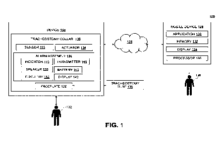
FIG. 1 depicts a block diagram of a system, according to at least some
embodiments
disclosed herein.
CA 03157200 2022-5-4
WO 2021/097420
PCT/US2020/060721
FIG. 2 depicts a perspective view of a device, according to at least some
embodiments
disclosed herein.
FIG. 3 depicts an exploded view of a device, according to at least some
embodiments
disclosed herein.
FIG. 4 depicts an exploded view of a device securable to a patient, according
to at least
some embodiments disclosed herein.
FIG. 5 depicts a perspective view of a device secured to a patient, according
to at least
some embodiments disclosed herein.
FIG. 6 depicts a perspective view of an alarm assembly of a device, according
to at least
some embodiments disclosed herein.
FIG. 7 depicts an exploded view of an alarm assembly of a device, according to
at least
some embodiments disclosed herein.
FIG. 8 depicts a perspective view of a launch pad for use with a device,
according to at
least some embodiments disclosed herein.
FIG. 9 depicts a block diagram of a Bluetooth Protocol Stack for use with a
device,
according to at least some embodiments disclosed herein.
FIG. 10 depicts a block diagram of a system, according to at least some
embodiments
disclosed herein.
FIG. 11 depicts a perspective view of a device worn by a patient, according to
at least
some embodiments disclosed herein.
FIG. 12 depicts a side view of a device worn by a patient according to at
least some
embodiments disclosed herein.
16
CA 03157200 2022-5-4
WO 2021/097420
PCT/US2020/060721
FIG. 13 depicts another side view of a device worn by a patient, according to
at least
some embodiments disclosed herein.
FIG. 14 depicts a perspective view of a device, according to at least some
embodiments
disclosed herein.
FIG. 15 depicts a block diagram of a computing device to be used with at least
the system
of FIG. 1, according to at least some embodiments disclosed herein.
Description of the Preferred Embodiments
The preferred embodiments of the present invention will now be described with
reference
to the drawings. Identical elements in the various figures are identified with
the same reference
numerals.
Reference will now be made in detail to each embodiment of the present
invention. Such
embodiments are provided by way of explanation of the present invention, which
is not intended
to be limited thereto. In fact, those of ordinary skill in the art may
appreciate upon reading the
present specification and viewing the present drawings that various
modifications and variations
can be made thereto.
FIG. 1 depicts a block diagram of a system 100. The system 100 of FIG. 1
includes a
device 104, a network 126 (such as the Internet), and a mobile device 128 (or
an electronic
device). The device 104 is configured to monitor, detect, and report movement
of a tracheostomy
tube 106. Moreover, the device 104 is configured to reduce accidental
decannulation.
As explained previously, the tracheostomy (or trach) tube 106 is a curved tube
that is
inserted into a tracheostomy stoma. A commonly used tracheostomy tube consists
of three parts:
an outer cannula with flange (e.g., a faceplate 122), inner cannula, and an
obturator. The outer
17
CA 03157200 2022-5-4
WO 2021/097420
PCT/US2020/060721
cannula holds the tracheostomy open. A faceplate 122 extends from the sides of
the outer tube
and has holes to attach cloth ties or Velcro strap around a neck of the
patient 102. The inner
cannula fits inside the outer cannula and has a locking feature to keep it
from being coughed out.
The obturator is used to insert a tracheostomy tube. More specifically, the
obturator fits inside
the tube to provide a smooth surface that guides the tracheostomy tube when it
is being inserted.
The device 104 includes a tracheostomy collar 108, a portion 162 (of FIG. 2,
FIG. 4, and
FIG. 5), and the faceplate 122. It should be appreciated that the faceplate
122 is releasably
attached to the tracheostomy collar 108 such that the faceplate 122 may be
used without the
tracheostomy collar 108, in examples. As illustrated in FIG. 3, the faceplate
122 includes a body
and a first end disposed opposite a second end. The body of the faceplate 122
includes an
opening 154 disposed therethrough. The opening 154 of the faceplate 122
receives a portion of
the tracheostomy tube 106 therein. The first end of the faceplate 122 includes
a first aperture 156
and the second end of the faceplate 122 includes a second aperture 158.
Moreover, the portion 162 (as shown in FIG. 3) includes an opening disposed
therethrough, which is configured to receive a portion of the tracheostomy
tube 106 therein.
Moreover, the portion 162 includes a first side disposed opposite a second
side. The first side of
the portion 162 includes a first opening 150A and the second side of the
portion 162 includes a
second opening 15011.
The tracheostomy collar 108 is releasably attachable to a patient 102. The
tracheostomy
collar 108 includes a main body having a first end and a second end. As shown
in FIG. 2, the
first end of the tracheostomy collar 108 includes a first attachment means
receivable through the
first aperture 156 of the faceplate 122. The second end of the tracheostomy
collar 108 includes a
second attachment means receivable through the second aperture 158 of the
faceplate 122.
18
CA 03157200 2022-5-4
WO 2021/097420
PCT/US2020/060721
In some examples, each of the first attachment means and the second attachment
means
comprise Velcro 160 (of FIG. 4), securing ties, strips, snaps, buckles,
pockets, loops, hooks,
clasps, and/or strings, among others. In other examples, each of the first
attachment means and
the second attachment means may comprise two or more attachment means. In this
illustrative
example of FIG. 2, each of the first attachment means and the second
attachment means may
comprise straps and snaps. For example, the first attachment means includes a
first strap 146A
and a first snap 144A and the second attachment means includes a second strap
146B and a
second snap 144B. As shown in at least FIG. 3 and FIG. 4, the first attachment
means (e.g., the
first strap 146A and the first snap 144A) is first received through the first
opening 150A of the
first side of the portion 162. Next, the first attachment means is received
through the first
aperture 156 of the faceplate 122. Moreover, as shown in at least FIG. 3, the
second attachment
means (e.g., the second strap 1468 and the second snap 14413) is first
received through the
second opening 1508 of the second side of the portion 162. Next, the second
attachment means
is received through the second aperture 158 of the faceplate 122, Then, each
of the first
attachment means and the second attachment means are affixed to the
tracheostomy collar 108.
Such affixes the portion 162 between the neck of the patient 102 and the
faceplate 122.
It should further be appreciated that the tracheostomy collar 108 is
adjustable in size. As
shown in FIG. 3, FIG. 4, and FIG. 5, a first portion 152 of the tracheostomy
collar 108 may slide
into an opening 150 of the tracheostomy collar 108 to reduce the size of the
tracheostomy collar
108. Then, the tracheostomy collar 108 may be snapped (using one or more of
the snaps 144 of
FIG, 4) or affixed to the desired size. In other examples, excess portions of
the tracheostomy
collar 108 may be cut and removed. FIG. 11, FIG. 12, and FIG. 13 depict the
device 104 affixed
to the patient 102.
19
CA 03157200 2022-5-4
WO 2021/097420
PCT/US2020/060721
The tracheostomy collar 108 may comprise one or more materials, such as foam,
cotton,
or neoprene, among others not explicitly listed herein. It should be
appreciated that the one or
more materials comprising the tracheostomy collar 108 may be selected such
that the one or
more materials support the components of the tracheostomy collar 108, protect
the patient's skin
from moisture, and protect the patient's skin from the faceplate of the device
104 and other
components.
Further, the tracheostomy collar 108 comprises numerous components, such as a
sensor
component 118 (of FIG. 1 and FIG. 2), an actuator component 124 (of FIG 1),
and/or an alarm
(or monitoring) assembly 114 (of FIG. 1, FIG. 3, FIG. 4, FIG. 5, FIG. 6, and
FIG. 7), among
others. It should be appreciated that the components of the tracheostomy
collar 108 may be
located in a front, a back, or a side of the tracheostomy collar 108 to
distribute weight evenly.
The sensor component 118 is located under, over, above, beside, or around the
faceplate 122 and
does not interfere with the tracheostomy tube 106. In preferred examples, the
sensor component
118 is located between the faceplate 122 and the neck of the patient 102, as
depicted in FIG. 2,
It should be appreciated that the sensor component 118 may be any type of
sensor, such
as a proximity sensor, a Hall-effect sensor, an infrared sensor, a laser
triangulation sensor, a laser
distance sensor, a laser displacement sensor, an ultrasonic sensor, a
photoelectric sensor, a
capacitive sensor, a fiberoptic sensor, a blood oxygenation sensor, an airflow
sensor, and/or a
reed switch sensor, among others not explicitly listed herein. In other
examples, the sensor
component 118 may measure one or more physiological parameters of the patient
102, such as a
temperature, a heart rate, a respiratory rate, a blood oxygen saturation, an
air-flow status, an
obstruction status, and/or an end-tidal capnography measurement, etc.. In some
examples, and as
depicted in FIG. 5, the sensor component 118 may be housed in a wound dressing
164.
CA 03157200 2022-5-4
WO 2021/097420
PCT/US2020/060721
The actuator component 124 is located under, over, above, beside, or around
the faceplate
and does not interfere with the tracheostomy tube. In preferred examples, the
actuator component
124 is located between the faceplate 122 and the neck of the patient 102. The
actuator
component 122 is configured to actuate when the sensor component 118 moves
from a first
position to a second position, from the first position to a third position,
and from the first position
to a fourth position. The first position, the second position, the third
position, and the fourth
position differ. It should be appreciated that the second position is further
from the actuator
component than the first position. The third position is further from the
actuator component than
the first position and the second position. Additionally, the fourth position
is further from the
actuator component 124 than the first position, the second position, and the
third position.
The sensor component 118 is also configured to transmit a signal to the alarm
assembly
114 in response to the actuator component 124 actuating. The alarm assembly
114 of the device
104 is configured to produce an alert in response to receiving the signal from
the sensor
component 118. The alarm assembly 114 (of FIG. 1, FIG. 3, FIG, 4, FIG, 5, FIG.
6, and FIG. 7)
includes numerous components, such as one or more indicators 116 (e.g., a
first indicator 116A,
a second indicator 116B, and/or a third indicator 116C, among others) (of FIG.
1, FIG. 2, FIG. 3,
and FIG. 6), a transmitter 140 (of FIG. 1), a speaker 120 (of FIG. 1, FIG. 3,
and FIG_ 6), a
battery 110 (of FIG. 1, FIG. 2, and FIG. 7), alarm circuitry 112 (of FIG. 1),
and/or a display 142
(of FIG. 1, FIG. 2, and FIG. 6), among other components not explicitly listed
herein. It should be
appreciated that the battery 110 may be rechargeable or non-rechargeable. In
some examples, the
battery 110 may be replaced with another power source (not shown).
The alarm circuitry 112, in some examples, may be housed in a remote component
(not
shown). The alarm circuitry 112 of the alarm assembly 114 may include
components such as: a
21
CA 03157200 2022-5-4
WO 2021/097420
PCT/US2020/060721
general-purpose microprocessor connected to an internal bus, The
microprocessor is adapted to
execute software, which may include an operating system and one or more
applications, as part
of performing the functions described herein. A read-only memory (ROM), a
random access
memory (RAM), the display 142, and the speaker 120 are also connected to the
interface bus.
The RAM and ROM are described for illustrative purposes only. Any computer-
readable
media may be used in the system for data storage. Computer-readable media are
capable of
storing information that can be interpreted by the microprocessor. This
information may be data
or may take the form of computer-executable instructions, such as software
applications, that
cause the microprocessor to perform certain functions and/or computer-
implemented methods.
Depending on the embodiment, such computer-readable media may comprise
computer storage
media and communication media. Computer storage media includes volatile and
non-volatile,
removable and non-removable media implemented in any method or technology for
storage of
information such as computer-readable instructions, data structures, program
modules or other
data. Computer storage media includes, but is not limited to, RAM, ROM, EPROM,
EEPROM,
flash memory or other solid state memory technology, CD-ROM, DVD, or other
optical storage,
magnetic cassettes, magnetic tape, magnetic disk storage or other magnetic
storage devices, or
any other medium which can be used to store the desired information and which
can be accessed
by components of the system.
The microprocessor of the alarm circuitry 112 may produce the alert in
response to
receiving the signal from the sensor component 118. In some examples, the
display 142 of the
alarm assembly 114 may exhibit a list of values that may generally apply to
the patient, such as,
for example, acceptable movement ranges for the tracheostomy tube 106. The
microprocessor
may then determine the proper thresholds using the user input data and
algorithms stored in the
22
CA 03157200 2022-5-4
WO 2021/097420
PCT/US2020/060721
ROM. The patient-specific thresholds may be stored on the RAM for comparison
to measured
movement of the tracheostomy tube 106. The memory of the alarm assembly 114
also stores user
data and information.
The alarm assembly 114 may project visual alerts/alarms and/or audio
alerts/alarms in
response to receiving the transmitted signal from the sensor component 120. In
an example, the
speaker 120 of the alarm assembly 114 is configured to produce an audio alert
in response to the
receiving the transmitted signal from the sensor component 120.
Further, in another example, each of the one or more indicators 116 (e.g., the
first
indicator 116A, the second indicator 116B, and/or the third indicator 116C)
comprise a light-
emitting diode (LED). In an illustrative example, a first indicator of the one
Of more indicators
116 emits a first color of light, a second indicator of the one or more
indicators 116 emits a
second color of light, and a third indicator of the one or more indicators 116
emits a third color
of light. Each of the first, second, and third color may differ. The first
color of light may be green
(e.g., associated with the tracheostomy tube 106 being in a proper position),
the second color of
light may be yellow (e.g., associated with a low battery level), and the third
color of light may be
red (e.g., associated with a high priority level associated with a large
amount of movement of the
tracheostomy tube 106 that may result in injury to a patient 102 associated
with the tracheostomy
tube 106). However, the quantity of the one or more indicators 116 and the
color of the one or
more indicators 116 is provided for illustrative purposes only. It should be
appreciated that other
quantities of the one or more indicators 116 and other colors of light are
contemplated.
In response to the actuator component 122 actuating when the sensor component
118
moves from the first position to the second position, the first indicator may
emit a first color of
light. In response to the actuator component 122 actuating when the sensor
component 118
23
CA 03157200 2022-5-4
WO 2021/097420
PCT/US2020/060721
moves from the first position to the third position, the second indicator may
emit a second color
of light. In response to the actuator component 122 actuating when the sensor
component 118
moves from the first position to the fourth position, the third indicator may
emit a third color of
In further examples, the alarm assembly 114 may comprise one or more
components or
buttons, such as buttons 148 of FIG. 2, to indicate an on status of the alarm
assembly 114, an off
status of the alarm assembly 114, a low power status of the battery 110, and a
silent mode for the
alarm assembly 114.
In a further example, in response to the actuator component 122 actuating when
the
sensor component 118 moves from the first position to the second position, a
first message (e.g.,
that the movement of the tracheostomy tube 106 is of low priority) may be
portrayed via the
display 142 of the alarm assembly 114. In response to the actuator component
122 actuating
when the sensor component 118 moves from the first position to the third
position, a second
message may be portrayed via the display 142 of the alarm assembly 114. In
response to the
actuator component 122 actuating when the sensor component 118 moves from the
first position
to the fourth position, a third message (e.g., that the movement of the
tracheostomy tube 106 is
of high priority) may be portrayed via the display 142 of the alarm assembly
114.
Each of the first, second, and third messages may differ. Further, each of the
first, second,
and third messages may contain images (e.g., an exclamation point indicating a
large movement
of the tracheostomy tube 106 and a high priority), letters (e.g., "low
movement," "high
movement," etc.), and/or numbers (e.g., a number of three for large movement
of the
tracheostomy tube 106 and a high priority or a number of one for a slight
movement of the
tracheostomy tube 106 and a low priority).
24
CA 03157200 2022-5-4
WO 2021/097420
PCT/US2020/060721
It should be appreciated that the device 104 is configured to communicate with
and/or
transmit data to another device, such as the mobile device 128 via Wi-Fl,
Bluetooth, Bluetooth
Low Energy (Bluetooth LE), or near-field communication (NFC). More
specifically, the
transmitter 140 of the alarm assembly 114 of the device 104 is configured to
transmit an audio
signal and/or a visual signal via the network 126 (such as the Internet) to
the mobile device 128
(e.g., the electronic device) in response to the production of the alert.
The mobile device 128 may be: a computer, a laptop computer, a smartphone, a
tablet, a
base station, an intercom system, a board alarm, and/or a remote station,
among other examples
not explicitly listed herein. The mobile device 128 may be associated with a
user 138, such as a
medical personnel, such as a doctor, a nurse, or a caregiver. Moreover, as
depicted in FIG. I, the
mobile device 128 may have numerous components, such as a memory 132, a
display 134, a
processor 136, and/or an application 130. The components of the mobile device
128 will be
discussed in greater detail herein.
Wireless LANs (WLANs) in which a mobile user can connect to a local area
network
(LAN) through a wireless connection may be employed for wireless
communications. Wireless
communications can include communications that propagate via electromagnetic
waves, such as
light, infrared, radio, and microwave. There are a variety of WLAN standards
that currently
exist, such as Bluetooth , Bluetooth LE, and IEEE 802.11.
By way of example, Bluetooth products may be used to provide links between
mobile
computers, mobile phones, portable handheld devices, personal digital
assistants (PDAs), and
other mobile devices and connectivity to the Internet. Bluetooth is a
computing and
telecommunications industry specification that details how mobile devices can
easily
interconnect with each other and with non-mobile devices using a short-range
wireless
CA 03157200 2022-5-4
WO 2021/097420
PCT/US2020/060721
connection. Bluetooth creates a digital wireless protocol to address end-user
problems arising
from the proliferation of various mobile devices that need to keep data
synchronized and
consistent from one device to another, thereby allowing equipment from
different vendors to
work seamlessly together.
As shown in FIG. 9, the Bluetooth Protocol Stack consists of layers of
software
abstractions from the user application interfaces with a Generic Attribute
Profile (GATT) layer
190 using an Application Program Interface (API) to provide services and
characteristics. The
Bluetooth Protocol Stack of FIG. 9 also has a bottom physical layer being a
controller 194 that
interfaces with the radio transmission hardware. A Generic Access Profile
(GAP) 192 provides
connection functionality between a server 198 and a client 196 (of FIG. 10).
More specifically,
FIG. 10 depicts the client-server connection between the mobile device 128 and
the
microcontroller (e.g., launchpad development board). FIG. 8 also depicts a
booster pack 188.
An IEEE standard, IEEE 802.11, specifies technologies for wireless LANs and
devices.
Using 802.11, wireless networking may be accomplished with each single base
station
supporting several devices. In some examples, devices may come pre-equipped
with wireless
hardware or a user may install a separate piece of hardware, such as a card,
that may include an
antenna. By way of example, devices used in 802.11 typically include three
notable elements,
whether or not the device is an access point (AP), a mobile station (STA), a
bridge, a personal
computing memory card International Association (PCMCIA) card (or PC card) or
another
device: a radio transceiver; an antenna; and a MAC (Media Access Control)
layer that controls
packet flow between points in a network.
As described herein, "NFC" is a set of communication protocols for
communication
between two electronic devices over a distance of 4 cm or less. NFC devices
can act as electronic
26
CA 03157200 2022-5-4
WO 2021/097420
PCT/US2020/060721
identity documents and keycards and may be used in contactless payment systems
and allow
mobile payment replacing or supplementing systems such as credit cards and
electronic ticket
smart cards. NFC can be used for sharing small files such as contacts, and
bootstrapping fast
connections to share larger media such as photos, videos, and other files.
In a preferred embodiment, and as depicted in FIG. 7, the alarm assembly 114
includes a
top housing 166 and a bottom housing 174, each of which form a waterproof
unit. The alarm
assembly 114 includes numerous internal components, such as a connected PCB
assembly 168, a
battery (such as the battery 110), a positive contact 170, a negative contact
172, firmware,
software, an adhesive sheeting 178, a screw 180 (such as a PCB screw), and/or
a seal 182 (such
as an 0-ring). The battery 110 may be a lithium battery, in examples. In other
examples, the
battery 110 may be a CR2 battery ultra-lithium. One or more securement
components 176 may
also be used to affix the top housing 166 to the bottom housing 174 to form
the waterproof unit,
with the internal components being disposed therein. In examples, the one or
more securement
components 176 may comprise screws or threaded screws. More specifically, the
one or more
securement components 176 may be threaded inserts. In some examples, the
adhesive sheeting
178 may be adhesive silicone sheeting. Further, the seal 182 may be a silicone
0-ring.
In an example, and as depicted in FIG. 8, the software of FIG. 7 includes a
development
board 184 for a launchpad 186, that contains one or more microcontrollers and
provides
functionality for the device 104. In some examples, the development board 184
for the launchpad
186 contains three microcontrollers and the booster pack 188. However, it
should be appreciated
that a quantity of the microcontrollers is not limited to any particular
quantity. The
microcontrollers are used to detect separation of the tracheostomy tube 106
from the trachea of
27
CA 03157200 2022-5-4
WO 2021/097420
PCT/US2020/060721
the patient 102, interface with the sensor component 118, and provide wireless
communication
capabilities to the mobile device 128.
A method to detect movement of the tracheostomy tube 108 is also described
herein. The
method includes numerous process steps, such as: affixing the tracheostomy
tube 106 to the
patient 102 and attaching the device 104 to the patient 102. The device 104 is
configured to
prevent movement of the tracheostomy tube 106. The device 104 comprises the
faceplate 122
and the tracheostomy collar 108. The tracheostomy collar 108 includes the
actuator component
124 and the sensor component 118 located proximate the faceplate 122. The
tracheostomy collar
108 also includes the alarm assembly 114 and the transmitter 140.
In response to detecting movement, by the sensor component 118, from a first
position to
a second position, from the first position to a third position, and from the
first position to a fourth
position, the method further includes the actuator component 124 actuating.
The first position,
the second position, the third position, and the fourth position differ.
Further, the second position
is further from the actuator component 124 than the first position. The third
position is further
from the actuator component 124 than the first position and the second
position Additionally,
the fourth position is further from the actuator component 124 than the first
position, the second
position, and the third position.
The method further includes: transmitting, by the sensor component 118, a
signal to the
alarm assembly 114 in response to the actuation of the actuator component 124;
producing, by
the alarm assembly 114, the alert in response to receiving the signal from the
sensor component
118; and transmitting, by the transmitter 140, the alert to the mobile device
128 via the network
126.
28
CA 03157200 2022-5-4
WO 2021/097420
PCT/US2020/060721
FIG. 15 is a block diagram of a computing/mobile device included within the
computer
system of FIG. 1. In some embodiments, the mobile device 128 (of FIG. 1) or
the computing
device 222 (of FIG. 15) may be utilized to implement one or more methods.
A basic configuration 232 of a computing device 222 is illustrated in FIG. 15
by those
components within the inner dashed line. In the basic configuration 232 of the
computing device
222, the computing device 222 includes a processor 234 and a system memory
224. In some
examples, the computing device 222 may include one or more processors and the
system
memory 224. A memory bus 244 is used for communicating between the one or more
processors
234 and the system memory 224.
Depending on the desired configuration, the processor 234 may be of any type,
including,
but not limited to, a microprocessor (pP), a microcontroller (p.(2), and a
digital signal processor
(DSP), or any combination thereof Further, the processor 234 may include one
more levels of
caching, such as a level cache memory 236, a processor core 238, and registers
240, among other
examples. The processor core 238 may include an arithmetic logic unit (ALU), a
floating point
unit (FPU), and/or a digital signal processing core (DSP Core), or any
combination thereof. A
memory controller 242 may be used with the processor 234, or, in some
implementations, the
memory controller 242 may be an internal part of the memory controller 242.
Depending on the desired configuration, the system memory 224 may be of any
type,
including, but not limited to, volatile memory (such as RAM), and/or non-
volatile memory (such
as ROM, flash memory, etc.), or any combination thereof The system memory 224
includes an
operating system 226, one or more engines, the application 130, and program
data 230. In some
embodiments, the application 130 may be an engine, a software program, a
service, or a software
29
CA 03157200 2022-5-4
WO 2021/097420
PCT/US2020/060721
platform, as described infra. The system memory 224 may also include a storage
engine 228 that
may store any information disclosed herein.
The second user 138 may engage with the application 130 of the mobile device
128 or the
computing device 222 to monitor movement of the tracheostomy tube 108. The
application 130
may receive the alert from the transmitter 124 of the alarm assembly 114 of
the tracheostomy
collar 104. In the case of a visual alert, such alert may be displayed via to
the display 134 to the
second user 138. In the case of an audio alert, such alert may be projected by
the speaker of the
mobile device 128.
Moreover, the computing device 222 may have additional features or
functionality, and
additional interfaces to facilitate communications between the basic
configuration 232 and any
desired devices and interfaces. For example, a bus/interface controller 248 is
used to facilitate
communications between the basic configuration 232 and data storage devices
246 via a storage
interface bus 250. The data storage devices 246 may be one or more removable
storage devices
252, one or more non-removable storage devices 254, or a combination thereof.
Examples of the
one or more removable storage devices 252 and the one or more non-removable
storage devices
254 include magnetic disk devices (such as flexible disk drives and hard-disk
drives (11DD)),
optical disk drives (such as compact disk (CD) drives or digital versatile
disk (DVD) drives),
solid state drives (SSD), and tape drives, among others.
In some embodiments, an interface bus 256 facilitates communication from
various
interface devices (e.g., one or more output devices 280, one or more
peripheral interfaces 272,
and one or more communication devices 264) to the basic configuration 232 via
the bus/interface
controller 256. Some of the one or more output devices 280 include a graphics
processing unit
CA 03157200 2022-5-4
WO 2021/097420
PCT/US2020/060721
278 and an audio processing unit 276, which are configured to communicate to
various external
devices, such as a display or speakers, via one or more AN ports 274.
The one or more peripheral interfaces 272 may include a serial interface
controller 270 or
a parallel interface controller 266, which are configured to communicate with
external devices,
such as input devices (e.g., a keyboard, a mouse, a pen, a voice input device,
or a touch input
device, etc.) or other peripheral devices (e.g., a printer or a scanner, etc.)
via one or more 1/0
ports 268.
Further, the one or more communication devices 264 may include a network
controller
258, which is arranged to facilitate communication with one or more other
computing devices
262 over a network communication link via one or more communication ports 260.
The one or
more other computing devices 262 include servers, the database, mobile
devices, and comparable
devices.
The network communication link is an example of a communication media. The
communication media are typically embodied by the computer-readable
instructions, data
structures, program modules, or other data in a modulated data signal, such as
a carrier wave or
other transport mechanism, and include any information delivery media. A
"modulated data
signal" is a signal that has one or more of its characteristics set or changed
in such a manner as to
encode information in the signal. By way of example, and not limitation, the
communication
media may include wired media (such as a wired network or direct-wired
connection) and
wireless media (such as acoustic, radio frequency (RF), microwave, infrared
(ER), and other
wireless media). The term "computer-readable media," as used herein, includes
both storage
media and communication media.
31
CA 03157200 2022-5-4
WO 2021/097420
PCT/US2020/060721
It should be appreciated that the system memory 224, the one or more removable
storage
devices 252, and the one or more non-removable storage devices 254 are
examples of the
computer-readable storage media. The computer-readable storage media is a
tangible device that
can retain and store instructions (e.g., program code) for use by an
instruction execution device
(e.g., the computing device 222). Any such, computer storage media is part of
the computing
device 222.
The computer readable storage media/medium can be a tangible device that can
retain
and store instructions for use by an instruction execution device. The
computer readable storage
media/medium may be, for example, but is not limited to, an electronic storage
device, a
magnetic storage device, an optical storage device, an electromagnetic storage
device, and/or a
semiconductor storage device, or any suitable combination of the foregoing_ A
non-exhaustive
list of more specific examples of the computer readable storage media/medium
includes the
following: a portable computer diskette, a hard disk, a random access memory
(RAM), a read-
only memory (ROM), an erasable programmable read-only memory (EPROM or Flash
memory),
a static random access memory (SRAM), a portable compact disc read-only memory
(CD-
ROM), a digital versatile disk (DVD), a memory stick, a floppy disk, and/or a
mechanically
encoded device (such as punch-cards or raised structures in a groove having
instructions
recorded thereon), and any suitable combination of the foregoing_ A computer
readable storage
medium, as used herein, is not to be construed as being transitory signals per
se, such as radio
waves or other freely propagating electromagnetic waves, electromagnetic waves
propagating
through a waveguide or other transmission media (e.g., light pulses passing
through a fiber-optic
cable), or electrical signals transmitted through a wire.
32
CA 03157200 2022-5-4
WO 2021/097420
PCT/US2020/060721
Aspects of the present invention are described herein regarding illustrations
and/or block
diagrams of methods, computer systems, and computing devices according to
embodiments of
the invention. It will be understood that each block in the block diagrams,
and combinations of
the blocks, can be implemented by the computer-readable instructions (e.g.,
the program code).
The computer-readable instructions are provided to the processor 234 of a
general
purpose computer, special purpose computer, or other programmable data
processing apparatus
(e.g., the computing device 222) to produce a machine, such that the
instructions, which execute
via the processor 234 of the computer or other programmable data processing
apparatus, create
means for implementing the functions/acts specified in the block diagram
blocks. These
computer-readable instructions are also stored in a computer-readable storage
medium that can
direct a computer, a programmable data processing apparatus, and/or other
devices to function in
a particular manner, such that the computer-readable storage medium having
instructions stored
therein comprises an article of manufacture including instructions, which
implement aspects of
the functions/acts specified in the block diagram blocks.
The computer-readable instructions (e.g., the program code) are also loaded
onto a
computer (e.g. the computing device 222), another programmable data processing
apparatus, or
another device to cause a series of operational steps to be performed on the
computer, the other
programmable apparatus, or the other device to produce a computer implemented
process, such
that the instructions, which execute on the computer, the other programmable
apparatus, or the
other device, implement the functions/acts specified in the block diagram
blocks.
Computer readable program instructions described herein can also be downloaded
to
respective computing/processing devices from a computer readable storage
medium or to an
external computer or external storage device via a network (e.g., the
Internet, a local area
33
CA 03157200 2022-5-4
WO 2021/097420
PCT/US2020/060721
network, a wide area network, and/or a wireless network). The network may
comprise copper
transmission cables, optical transmission fibers, wireless transmission,
routers, firewalls,
switches, gateway computers, and/or edge servers. A network adapter card or
network interface
in each computing/processing device receives computer readable program
instructions from the
network and forwards the computer readable program instructions for storage in
a computer
readable storage medium within the respective computing/processing device.
Computer readable program instructions for carrying out operations of the
present
invention may be assembler instructions, instruction-set-architecture (ISA)
instructions, machine
instructions, machine dependent instructions, microcode, firmware
instructions, state-setting
data, configuration data for integrated circuitry, or either source code or
object code written in
any combination of one or more programming languages, including an object
oriented
programming language such as Smalltalk, C++, or the like, and procedural
programming
languages, such as the "C" programming language or similar programming
languages. The
computer readable program instructions may execute entirely on the user's
computer/computing
device, partly on the user's computer/computing device, as a stand-alone
software package,
partly on the user's computer/computing device and partly on a remote
computer/computing
device or entirely on the remote computer or server. In the latter scenario,
the remote computer
may be connected to the user's computer through any type of network, including
a local area
network (LAN) or a wide area network (WAN), or the connection may be made to
an external
computer (for example, through the Internet using an Internet Service
Provider). In some
embodiments, electronic circuitry including, for example, programmable logic
circuitry, field-
programmable gate arrays (FPGA), or programmable logic arrays (PLA) may
execute the
computer readable program instructions by utilizing state information of the
computer readable
34
CA 03157200 2022-5-4
WO 2021/097420
PCT/US2020/060721
program instructions to personalize the electronic circuitry, in order to
perform aspects of the
present invention.
Aspects of the present invention are described herein with reference to block
diagrams of
methods, computer systems, and computing devices according to embodiments of
the invention.
It will be understood that each block and combinations of blocks in the
diagrams, can be
implemented by the computer readable program instructions.
The block diagrams in the Figures illustrate the architecture, functionality,
and operation
of possible implementations of computer systems, methods, and computing
devices according to
various embodiments of the present invention. In this regard, each block in
the block diagrams
may represent a module, a segment, or a portion of executable instructions for
implementing the
specified logical function(s). In some alternative implementations, the
functions noted in the
blocks may occur out of the order noted in the Figures. For example, two
blocks shown in
succession may, in fact, be executed substantially concurrently, or the blocks
may sometimes be
executed in the reverse order, depending upon the functionality involved, It
will also be noted
that each block and combinations of blocks can be implemented by special
purpose hardware-
based systems that perform the specified fimctions or acts or carry out
combinations of special
purpose hardware and computer instructions.
The descriptions of the various embodiments of the present invention have been
presented for purposes of illustration, but are not intended to be exhaustive
or limited to the
embodiments disclosed. Many modifications and variations will be apparent to
those of ordinary
skill in the art without departing from the scope and spirit of the described
embodiments. The
terminology used herein was chosen to best explain the principles of the
embodiments, the
CA 03157200 2022-5-4
WO 2021/097420
PCT/US2020/060721
practical application or technical improvement over technologies found in the
marketplace, or to
enable others or ordinary skill in the art to understand the embodiments
disclosed herein.
When introducing elements of the present disclosure or the embodiments
thereof, the
articles "a," "an," and "the" are intended to mean that there are one or more
of the elements.
Similarly, the adjective "another," when used to introduce an element, is
intended to mean one or
more elements. The terms "including" and "having" are intended to be inclusive
such that there
may be additional elements other than the listed elements.
Although this invention has been described with a certain degree of
particularity, it is to
be understood that the present disclosure has been made only by way of
illustration and that
numerous changes in the details of construction and arrangement of parts may
be resorted to
without departing from the spirit and the scope of the invention.
36
CA 03157200 2022-5-4