Note: Descriptions are shown in the official language in which they were submitted.
CA 0=827 2022-04-12
WO 2021/084155
PCT/F12019/050768
1
METHOD FOR PROCESS WATER TREATMENT
TECHNICAL FIELD
The current disclosure relates to a method for
treating process water of a flotation arrangement. In
particular, the invention is intended for treating
process waters of a flotation arrangement comprising a
number of mineral flotation circuits, each mineral
flotation circuit arranged to recover a specific
valuable metal or mineral.
BACKGROUND
The quality of mineral ores is decreasing as
best deposits are increasingly already in use or have
been used. Therefore the mined ores may contain
significantly less valuable material. In order to run
profitable operations, it is necessary to liberate all
valuable metals or other valuable materials from the
deposits, i.e. utilise polymetallic processes to obtain
several different metals from single ore source to keep
the operations economically sound.
In flotation processes, different metals
and/or minerals require specific flotation chemicals
and process conditions to allow recovery of the desired
valuable material. This is not a problem if open water
circuits are possible to be used. In that case, fresh
water may be added into the processes whenever needed,
and used process water contaminated by flotation
chemicals intended for a specific metal or mineral may
be freely discarded. Residual flotation chemicals and
build-up of harmful components in the process waters is
not an issue.
Typically, the gangue froth removed in the
reverse flotation is sent to a tailings dam where the
long resident time, typically 20-40 days, is expected
to sediment and separate the solids, as well as
decompose residual flotation chemicals from the
CA 0=827 2022-04-12
WO 2021/084155
PCT/F12019/050768
2
collected and reusable process water. The collected
process water is then recirculated back into the
beneficiation process. The quality of the recirculated
process water plays a significant role in obtaining
target recoveries and qualities of the final product.
Today, water shortage, ecological demands
placed by legislation and public pressure, costs and
extensive space requirements of the aforementioned
conventional tailings methods for process water
treatment increasingly put pressure to recirculate
process waters as main processes in flotation become at
least partially closed-loop systems in terms of water
usage. Alternative methods for treatment of tailings
flows that enables least partially closed-loop water
systems may be needed.
A conventional process water or tailings
treatment method with typical resident time of 20-40
days may result in acceptable water quality, allowing
the treated process water to be reused in the main
flotation process, and in other process steps. Apart
from being time-consuming, and the conventional
treatment method has significant space requirements and
is also subject to problems for example due to rain,
breakage, and maintenance. Even though residual
chemicals become decomposed in the tailings dam due to
the long retention time and exposure to UV irradiation,
the separated water still may still contain undesired
material at least in soluble form. Fines do not have
enough time to settle into the sediment. Therefore the
water may still be contaminated in view of utilisation
in flotation circuits intended for recovery of specific
metals/minerals.
When process water treated in a conventional
manner is recirculated back into the main flotation
processes of a polymetallic operation, it may contain
flotation chemicals that are not meant for the specific
flotation process or floating of a specific metal or
CA 03157827 2022-04-12
WO 2021/084155
PCT/F12019/050768
3
other valuable material. Undesired valuable material
may end up floated and recovered during the flotation
process of another metal, or bulk flotation takes place.
Other negative effects of the above are floating drafts,
changes in viscosity of the slurry/pulp, and changes in
hydrophobicity which disrupts the working of gravity
separators and leads to loss of recovery. Overall,
closed water systems result to problems in flotation
process runnability and increases disturbances, which
makes controlling the flotation process more
challenging.
Increase of fine material in thickener
overflow may increase the flotation chemical dosage or
decrease recovery and quality of desired valuable
material. Fines load may also be increased by the need
to further comminute low quality ore material by
grinding to a smaller particle size, in order for the
ore to be in a form that allows recovery of valuable
material. Build-up of fines, as well as impurities such
as microbes and organic material affects subsequent
dewatering negatively.
Fine material, especially of silicate origin,
disturb the ability of collector chemicals to function
as intended because the silica-containing fines may
have opposite surface potentials and may thus attach to
mineral surfaces and cause steric effect that prevents
collectors from attaching onto the particles, or a
steric layer so thick that the collector molecule length
is not sufficient to make the ore particles hydrophobic
- apparent surface energy remains unmodified and
attachment to flotation gas bubbles cannot happen.
Further, fines comprising only undesired
material are more difficult depress into
underflow/tailings. Selectivity of reagents decreases
with increasing fines amount. Fines in the form of
compounds such as colloidal hydroxides and carbonates
present in the flotation circuit may become combined
CA 03157827 2022-04-12
WO 2021/084155
PCT/F12019/050768
4
and cause large surface areas that react with flotation
chemicals and use them up.
Changing over to other tailings methods such
as thickened tailings, paste, dry stacking or hybrids
of these, will result in much shorter sedimentation time
due to the new thickeners needed in these process steps.
This leads to much shorter sedimentation time, 3-8 h,
that result in more fines, residual chemicals and other
harmful or detrimental substances ending up in the
thickener overflow, and later in recycled process
water.
Chemicals and other compounds build up in a
closed water loop, as these substances cannot be
efficiently removed by standard dewatering operations.
Thus, for example, a thickener overflow will comprise
material that is difficult to settle, and residual
chemicals that will negatively affect the main
flotation process. These need to be removed from the
overflow if process water is to be recirculated without
causing problems in the main processes due to residual
flotation chemicals etc. carried over from the
dewatering.
Reverse osmosis with semipermeable membranes,
nanofiltration, and the like water cleaning methods are
very energy-intensive, and in a sense produce "too
clean" water. For example, hardness of water is affected
as compounds such as K, Ca, Mn, Mg become removed as
well. This may not be beneficial in regard to flotation
process efficiency when the cleaned water is
recirculated back into flotation processes. Further,
these methods require bulky technical solutions such as
pre-evaporation and different membranes that are
sensitive and expensive.
It is also possible to employ a thickener or
a dewatering press after each flotation circuit of a
flotation arrangement, and to recirculate the thus
separated process water back into each respective
CA 0=827 2022-04-12
WO 2021/084155 PCT/F12019/050768
flotation circuit so that the flotation chemistries are
not mixed, and any residual chemicals are appropriate
for each flotation process within a flotation circuit.
Fines may still pose a problem as this kind of system
5 does not depress fines efficiently due to the relatively
short residence time. Also microbiological contaminants
may cause problems.
Conventional solution to control the
accumulation of collector chemicals and suppress
microbiological growth is to send the flotation froth
to the tailings dam with a long retention time. Another
method is to use a chemical oxidant, e.g. Na0C1, which
can be added before a thickener to decompose collector
chemicals and improve sedimentation of very fine
material. However, a drawback of using such chemicals
are higher Cl levels than can lead to equipment
corrosion and failure. They are also hazardous to
environment and personnel due to formation of C12, if
used in acidic conditions. It will also affect the
entire flotation operation, making chemical dosage and
process control more difficult.
SUMMARY OF THE INVENTION
The method according to the current disclosure
is characterized by what is presented in claim 1.
A method for treating process water of a
flotation arrangement is disclosed. The flotation
arrangement comprises a mineral flotation line
comprising a first mineral flotation circuit for
treating ore particles comprising valuable materials,
the ore particles suspended in slurry, for the
separation of slurry into underflow and overflow
comprising recovered first valuable material, and a
second mineral flotation circuit arranged to receive
underflow of the first flotation circuit as slurry
infeed, for the separation of slurry into underflow and
overflow comprising recovered second valuable material;
CA 0=827 2022-04-12
WO 2021/084155
PCT/F12019/050768
6
and a process water treatment arrangement for treating
underflow of the of the mineral flotation line. The
method comprises the steps of a) dewatering underflow
in a gravitational solid-liquid separator to separate
a sediment from a supernatant comprising water,
residual flotation chemicals in colloidal and soluble
compounds, fine particles, and microbes; b) subjecting
the supernatant to cleaning flotation, in which at least
90 % of the flotation gas bubbles have a size from 0,2
to 250 pm, in a cleaning flotation unit for collecting
at least fine particles and residual flotation
chemicals, for separating at least fine particles and
residual flotation chemicals from the supernatant into
cleaning flotation overflow, and for forming purified
process water as cleaning flotation underflow, c)
removing cleaning flotation overflow as tailings, and
d) recirculating purified process water into the
mineral flotation line.
With the invention the aforementioned problems
in water recirculation and downsides associated with
conventional solutions may be alleviated. Overflow or
supernatant from the gravitational solid-liquid
separator is subjected to cleaning flotation in a
cleaning flotation unit so that fine particles, i.e.
particles with particle size below 20 pm together with
residual flotation chemicals (especially collector
chemicals) may be 1) floated and collected into overflow
of the cleaning flotation - the collector chemicals
carried over from the main flotation processes act as
collectors to the fine particles, 2) separated from the
thus purified process water by the cleaning flotation
step, and 3) collected away as tailings to be further
treated. The resulting purified process water can then
be recirculated back into the main flotation process.
As the purified process water comprises
significantly less residual flotation chemicals and
CA 03157827 2022-04-12
WO 2021/084155
PCT/F12019/050768
7
fine particles, it will not affect the main flotation
process detrimentally.
As the overflow from the mineral or main
flotation process resides relatively short time in the
gravitational solid-liquid separator, the flotation
chemicals, collectors carried over in overflow from the
main flotation process, do not decompose, as would
happen in a conventional tailings dam over time. These
collector chemicals may then be utilised in the cleaning
flotation step as collectors, thereby making the
floating and collection of desired material possible,
i.e. collection of fine particles, thus resulting in
purified process water.
At the same time, these residual flotation
chemicals become used up, and they do not carry over
back into the main mineral flotation process when the
purified process water is recirculated back. Thus, the
main flotation process is unaffected by such undesired
flotation chemicals, making the controlling of the
mineral flotation process easier.
In the cleaning flotation process, other
colloidal material such as C, P, N present in very fine
particles may also be removed, as well as any starch-
based depressants present in the process water, thereby
removing nutrients that would promote microbiological
growth in the purified process water. This may improve
the result of any subsequent water treatment stages such
as filtering. For example, the removal of such material
may prevent blocking of filter orifices of ceramic
filters.
As the slurry or gravitational solid-liquid
separator overflow comprises only fine particles
(larger particles end up in sediment), the cleaning
flotation may be energy-efficiently utilized at a stage
where it is most efficient, i.e. for removing fine
particles.
CA 0=827 2022-04-12
WO 2021/084155
PCT/F12019/050768
8
In an embodiment of the method according to
the invention, a first process water treatment
arrangement is arranged to treat underflow of the second
mineral flotation circuit.
In an embodiment, the first mineral flotation
circuit is arranged to recover Cu, and the second
mineral flotation circuit is arranged to recover Ni.
In an embodiment, the mineral flotation line
further comprises a third mineral flotation circuit
arranged to receive underflow of the second mineral
flotation circuit as slurry infeed, for the separation
of slurry into underflow and overflow comprising
recovered third valuable material, and that a process
water treatment arrangement is arranged to treat
underflow of the third mineral flotation circuit.
In a further embodiment, the first mineral
flotation circuit is arranged to recover Cu, the second
mineral flotation circuit is arranged to recover Ni,
and third mineral flotation circuit is arranged to
recover sulphide.
In an embodiment, the flotation arrangement
comprises a first process water cleaning arrangement
for treating underflow of the second mineral flotation
circuit and a second process water cleaning arrangement
for treating underflow of the third mineral flotation
circuit.
In a further embodiment, cleaning flotation
overflow of the first process water cleaning
arrangement is directed to the third mineral flotation
circuit as slurry infeed.
Typical polymetallic flotation operation
concerns the recovery of Cu, Ni, and sulphides. The
flotation chemicals (collectors) employed in floating
and recovery of copper naturally work only on ore
particles comprising Cu. Copper is typically very
easily floated material, and therefore it is recovered
in a first flotation circuit. On the other hand, in a
CA 03157827 2022-04-12
WO 2021/084155 PCT/F12019/050768
9
subsequent nickel flotation process, the recovery of
ore particles comprising Ni is not detrimentally
affected by the Cu specific chemicals, which are carried
over into the Ni flotation circuit as underflow of the
Cu flotation circuit is led into the subsequent Ni
flotation circuit as slurry infeed. Therefore it may
not be necessary to clean the process water in between
the two first flotation circuits.
However, if the process water from Ni
flotation circuit underflow, or final underflow of such
a flotation operation, is to be recirculated back into
the front end (Cu flotation circuit) of the main
flotation operation, the Ni specific flotation
chemicals in the process water do affect the recovery
of Cu detrimentally. The efficiency of Ni recovery
depends on the performance and selectivity of Cu
circuit, and problems in the Cu circuit caused by carry-
over residual flotation chemicals or fine particles in
the recirculated process water may thus also affect the
operational performance of the subsequent Ni circuit.
Therefore it is necessary to treat final underflow of
the flotation operation or line before recirculating
any process water back into the main flotation process.
Similarly, the sulphide recovery process in
the sulphide flotation circuit is not detrimentally
affected by the residual Cu and/or Ni residual flotation
chemicals, but recirculating process water from the
sulphide flotation circuit requires cleaning of the
process water from any residual chemicals, as these may
affect the operation of the first flotation circuit.
In each embodiment, the removal of fine
particles of various sources from the process water is
in any case very beneficial to the main flotation
process. It is also foreseeable that underflow from the
second flotation circuit (comprising residual flotation
chemicals from the Cu and Ni flotation circuits) is
cleaned in a first process water cleaning arrangement,
CA 03157827 2022-04-12
WO 2021/084155
PCT/F12019/050768
from which the purified process water may be
recirculated into the main flotation process or
flotation line, and overflow of the cleaning flotation
directed to the third flotation circuit as slurry infeed
5 to effect the recovery of a third valuable material,
i.e. sulphides. The third flotation circuit may then be
followed by a second process water cleaning arrangement
for removing residual sulphide flotation chemicals
prior to recirculating a purified process water back
10 into the main flotation process or line.
In an embodiment, the cleaning flotation unit
is a dissolved gas (DAF) flotation unit.
DAF is a microflotation process which is used
in various applications in water or effluent
clarification. Solid particles are separated from
liquid by using very small flotation gas bubbles,
microbubbles. The microbubbles with a size range of 30
- 100 pm are generated by dissolving air or other
flotation gas into the liquid under pressure. The
bubbles are formed in a pressure drop when dispersion
is released. The particles of solid form attach to the
bubbles and rise to the surface. A formed, floating
sludge is removed from the liquid surface with sludge
rollers as DAF overflow. Chemicals may sometimes be
needed to aid flocculation and increase solids removal
efficiency. Typically, colloids removal is possible
with efficient coagulation.
In an embodiment, prior to step b), the
temperature of the supernatant is 2 to 70 C.
In an embodiment, prior to step b) pH of the
supernatant is 5 to 14.
The temperature and/or the pH of the
supernatant may be inherent, i.e. caused by the
preceding process steps or environment, or, when
desired, the properties may be adjusted as needed, for
example to optimise the cleaning flotation in step b).
CA 03157827 2022-04-12
WO 2021/084155
PCT/F12019/050768
11
In an embodiment, in step a), the residence
time of overflow in the gravitational solid-liquid
separator in under 10 hours, preferably 2 to 8 hours.
In an embodiment, the solids content of the
sediment of the gravitational solid-liquid separator is
at least 80 w-%.
A relatively short residence time means that
the flotation chemicals, in particular the collector
chemicals are not decomposed but are carried over with
the supernatant, and they may be utilised in the
subsequent cleaning flotation step. By effecting a high
enough solids content into the sediment, the amount of
solid tailings to be treated may be decreased.
In an embodiment, after step a), the
supernatant is led into a separator overflow tank.
A separator overflow tank may be used to control
the flow of supernatant into the cleaning flotation
unit, or into a mixing unit, if such is used. This may
help in stabilizing the overall process water treatment
operation, as the flow supernatant into the subsequent
operational steps is controlled.
In an embodiment, prior to step b), the
supernatant is chemically conditioned by adding a
coagulant, and/or a flocculant, and/or an additional
flotation chemical.
In a further embodiment, the coagulator is
chosen from a group comprising: bentonite, fixatives,
aluminium salts, iron salts, polymer coagulants.
In a further embodiment, the coagulant is
polyaluminium chloride.
In a further embodiment, PAC is added into the
supernatant in an amount of 0 to 500 ppm.
In an embodiment, the supernatant is further
conditioned by adding a flocculant.
In a further embodiment, a polymer flocculant
is added into the supernatant in an amount of 0 to 50
ppm.
CA 0=827 2022-04-12
WO 2021/084155
PCT/F12019/050768
12
In an embodiment, at least one additional
flotation chemical is chosen from a group comprising:
collectors, activators, depressants,
frothers,
modifiers.
While normally there are enough flotation
chemicals (such as collector chemicals) present as
carry-over from the main flotation process in the
supernatant, in some cases, it may be necessary to
condition the supernatant before the DAF treatment, to
ensure that enough of the carry-over fine particles may
be removed by the DAF unit. This may be done in a mixing
unit configured to allow addition of different
chemicals, such as flocculants and/or coagulants and/or
conventional flotation chemicals used as additional
flotation chemicals, and treatment of fluid with those
chemicals. The amount of coagulant and/or flocculant
and/or additional flotation chemical is chosen based on
the process, and is highly directed by cost of the
chemicals. Organic coagulants are more expensive than
inorganic ones. Typically, flocculants are added in
amounts under 10 ppm.
In an embodiment, prior to step d), the purified
process water is subjected to filtration for removing
chemicals promoting microbiological growth.
In a further embodiment, in filtration, a
filtering unit comprising a ceramic filter is used.
By filtering the purified process water, other
harmful components may be removed, thus promoting to
cleanliness of the water to be recirculated back into
the main flotation process. For example, sliming of
equipment may be decreased.
By using the cleaning flotation unit for
treating the supernatant, as well as the fine particles,
a major part of the chemical residues in particle form
may be removed from the purified process water. This
allows the utilisation of ceramic filter plates - in
ceramic filter plates, the filter pores may be
CA 0=827 2022-04-12
WO 2021/084155
PCT/F12019/050768
13
susceptible to blocking by particles of a certain size
range. By removing those particles at least partially,
blockages may be avoided, and the operation of the
filtering unit improved.
In an embodiment, in step b) at least 20 % of
the fine particles are removed from underflow of the
mineral flotation line.
In an embodiment, in step b) at least 20 % of
the residual flotation chemicals are removed from
underflow of the mineral flotation line.
The aim of the method is to remove as much of
the fine particles and residual flotation chemicals
from the mineral flotation line underflow as possible.
Fine particles and residual chemicals remaining in the
purified process water are detrimental to the main
flotation process, and may decrease the quality and
value of the end product (valuable metals/minerals).
Both instances also decrease efficiency of the mineral
flotation processes. Removal of excess fine particles
and residual flotation chemicals may decrease the
consumption of fresh flotation chemicals, and fresh
water.
In an embodiment, hardness of the purified
process water is unaffected by the process water
treatment arrangement.
Maintaining water hardness at a goal level
allows the controlling of the main flotation process as
desired. Flotation chemical addition can be kept at a
constant level as water hardness is constant, and
hydrophobic particles improves the mineral flotation
when hardness is at a certain level. Conventional water
treatment methods, such as nanofiltration membranes or
reverse osmosis membranes may effect water hardness as
compounds (Ca, K, Mn, Mg) become removed together with
the detrimental substances. A cleaning flotation unit
allows these compounds remain in water, as they are not
CA 0=827 2022-04-12
WO 2021/084155
PCT/F12019/050768
14
collected into the cleaning flotation overflow and
removed into tailings.
BRIEF DESCRIPTION OF THE DRAWINGS
The accompanying drawings, which are included
to provide a further understanding of the current
disclosure and which constitute a part of this
specification, illustrate embodiments of the disclosure
and together with the description help to explain the
principles of the current disclosure. In the drawings:
Figs. 1-4 are a simplified presentations of
flotation arrangements in which embodiments of the
method according to the invention may be used.
DETAILED DESCRIPTION
Reference will now be made in detail to the
embodiments of the present disclosure, an example of
which is illustrated in the accompanying drawings.
The description below discloses some
embodiments in such a detail that a person skilled in
the art is able to utilize the flotation method based
on the disclosure. Not all steps of the embodiments are
discussed in detail, as many of the steps will be
obvious for the person skilled in the art based on this
disclosure.
For reasons of simplicity, item numbers will
be maintained in the following exemplary embodiments in
the case of repeating components.
The enclosed figures 1-4 illustrate a
flotation arrangement 1 in a schematic manner. The
figures are not drawn to proportion, and many of the
components of are omitted for clarity. Some of the
components are presented as boxes representing an
entire process or arrangement.
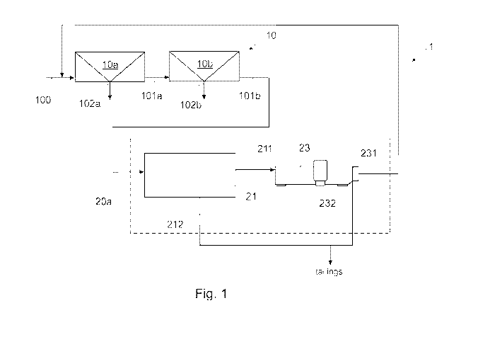
The flotation arrangement 1 comprises a
mineral flotation line 10. The mineral flotation line
10 in turn comprises a first mineral flotation circuit
CA 03157827 2022-04-12
WO 2021/084155
PCT/F12019/050768
10a arranged to treat ore particles comprising valuable
materials, suspended in slurry 100, so that the slurry
is separated into underflow 101a and overflow 102a.
Overflow 102a comprises a recovered first valuable
5 material. In an embodiment, the first valuable material
comprises Cu. I.e. the first mineral flotation circuit
10a may be arranged to treat mineral ore particles
comprising Cu.
The mineral flotation line 10 further
10 comprises a second mineral flotation circuit 10b, which
is arranged to receive underflow 101a from the first
mineral flotation circuit 10a as slurry infeed. The
second mineral flotation circuit 10b is arranged to
separate slurry into underflow 101b and overflow 102b
15 comprising a second valuable material. In an
embodiment, the second valuable material comprises Ni.
I.e. the second mineral flotation circuit 10b may be
arranged to treat mineral ore particles comprising Ni.
The mineral flotation line 10 may further
comprise a third mineral flotation circuit 10c, which
may be arranged to receive underflow 101b from the
second mineral flotation circuit 10b as slurry infeed.
In an embodiment, the third mineral flotation circuit
10c is arranged to receive cleaning flotation overflow
232a from a process water cleaning arrangement 20a as
slurry infeed (see Fig. 4). The third mineral flotation
circuit 10c is arranged to separate slurry into
underflow 101c and overflow 102c comprising a third
valuable material. In an embodiment, the third valuable
material comprises sulphides. I.e. the third mineral
flotation circuit 10c may be arranged to treat mineral
ore particles comprising sulphides.
Underflows 101a, 101b, 101c may comprise
unrecovered ore particles with a particle size below 20
pm, i.e. in a size range falling within the "fine
particle" size distribution, silicate-containing
particles, soluble SiO2 and other undesired, detrimental
CA 03157827 2022-04-12
WO 2021/084155
PCT/F12019/050768
16
or unrecovered material or compounds such as fine
particles and larger particles comprising C, P, N, Ca,
K, Mn, Mg; residual flotation chemicals such as
collector chemicals or starch-based depressants,
microbes, etc., suspended and/or dissolved in water.
The flotation arrangement 1 further comprises
a process water treatment arrangement 20, intended for
treating underflow of the mineral flotation line 10,
i.e. underflow 101b, 101c of a mineral flotation circuit
10b, 10c. The process water treatment arrangement 20
comprises a gravitational solid-liquid separator 21 in
which underflow from the mineral flotation line 10 is
dewatered in a conventional manner, i.e. by separating
a sediment 212 comprising larger, heavier particles
from a supernatant 211 comprising the aforementioned
solid compounds in a fine particle range, as well as
any residual flotation chemicals, soluble SiO2, microbes
and water. The gravitational solid-liquid separator 21
may, for example, be a thickener (as shown in Fig. 3)
or a clarifier.
The process water treatment arrangement 20
further comprises a cleaning flotation unit 23. The
cleaning flotation unit employs flotation gas to float
particles collected by collector chemicals. In
particular, flotation in the cleaning flotation unit 23
is executed by utilising microbubbles, or flotation gas
bubbles having a particular size range. In the cleaning
flotation and cleaning flotation unit 23 according to
the invention, at least 90 % of the flotation gas
bubbles fall into a size range of 2 to 250 pm. The
cleaning flotation may employ dissolved gas flotation
(DAF), and the cleaning flotation unit 23 may be a DAF
unit. Other methods for effecting flotation with
smaller sized flotation gas bubbles may also be
employed, such as electrical double layer flotation or
membrane flotation.
CA 0=827 2022-04-12
WO 2021/084155
PCT/F12019/050768
17
In the cleaning flotation unit 23, the
supernatant 211 is subjected to flotation in order to
collect at least fine particles with the help of
residual flotation chemicals, i.e. collector chemicals
carried over from the mineral flotation circuits 10a,
10b, 10c. Since the flotation chemicals become adsorbed
onto the solid fine particles during the cleaning
flotation, also these residual flotation chemicals
become collected. Additionally also other particles
such as particles comprising C, P, N may be collected
and removed in the cleaning flotation.
In an embodiment of the invention, the
supernatant 211 comprises an amount of residual
flotation chemicals (for example Cu, and/or Ni, and/or
sulphide specific collectors) as carry-over from the
mineral flotation processes in the mineral flotation
line 10 sufficient to collect a significant part of the
fine particles, as well as to coagulate any soluble
detrimental compounds into solid form particles.
Subsequently, at least fine particles are
separated from the supernatant into cleaning flotation
overflow 232 and removed from the flotation arrangement
1 as tailings. Concurrently, purified process water 231
is formed in the cleaning flotation unit 23 as cleaning
flotation underflow. The purified process water 231 may
then be recirculated back into the mineral flotation
line 10 to be used for example as dilution water for
slurry 100 infeed.
The purified process water 231 may be further
treated in a filtering unit 24 to remove microbes and
chemicals promoting microbiological growth, or to
remove any other undesired chemicals from the purified
process water 231 (see Fig. 2). The filtering unit 24
may be of any type known in the field. In an embodiment,
the filtering unit 24 comprises a ceramic filter or a
number of ceramic filters.
CA 0=827 2022-04-12
WO 2021/084155
PCT/F12019/050768
18
Further, the process water treatment
arrangement 20 may comprise a separator overflow tank
21b directly after the gravitational solid-liquid
separator 21 (see Fig. 2). The supernatant 211 is led
into the separator overflow tank 21b prior to directing
it into the cleaning flotation unit 23, for example to
control the volumetric flow into the cleaning flotation
unit 23.
Further, additionally or alternatively, the
process water treatment arrangement 20 may comprise a
mixing unit (not shown in the figures) after the
gravitational solid-liquid separator, or after the
separator overflow tank 21b, if one is employed. The
mixing unit may be of any type known in the field,
arranged to enable the addition of desired chemicals
such as coagulants and/or flocculants and the treatment
of the supernatant 211 by chemical conditioning so that
at least the silica-containing particles may be
flocculated prior to leading the supernatant 211 into
the DAF unit 23. Also soluble SiO2 may be thus
flocculated into solid form particles and thus
subsequently removed from the purified process water.
The addition of coagulant and/or flocculant
and/or additional flotation chemical may be required,
should the supernatant 211 not comprise a sufficient
amount of residual collector chemicals as carry-over
from the flotation circuit 10, to ensure sufficient
flotation of fine particles, or for example
flocculation of silica-containing particles in the
cleaning flotation unit 23, or ensure the creation of
sufficiently large flocs in the cleaning flotation unit
23.
Both the separator overflow tank 21b and the
mixing unit may be further utilised to adjust the
temperature and/or pH of the supernatant 211, if
desired, to prepare the supernatant for the cleaning
flotation.
CA 0=827 2022-04-12
WO 2021/084155
PCT/F12019/050768
19
In an embodiment, the mineral flotation line
comprises two mineral flotation circuits 10a, 10b, and
the process water treatment arrangement 20 is arranged
to treat underflow 101b of the second mineral flotation
circuit 10b (see Figs. 1 and 2). In an embodiment, the
mineral flotation line 10 comprises three mineral
flotation circuits 10a, 10b, 10c, and the process water
treatment arrangement 20 is arranged to treat underflow
101c of the third mineral flotation circuit 10c (see
Fig. 3). In an
embodiment, the flotation arrangement
1 comprises three mineral flotation circuits 10a, 10b,
10c; as well as a first process water treatment
arrangement 20a, arranged to treat underflow 101b of
the second mineral flotation circuit 10b, and a second
process water treatment arrangement 20b arranged to
treat underflow 101c of the third mineral flotation
circuit 10c (see Fig. 4). The first process water
treatment arrangement 20a and the second process water
treatment arrangement 20b have the features as
described above in connection with the process water
treatment arrangement 20.
In the embodiment, the cleaning flotation
overflow 232a from the cleaning flotation unit of the
first process water treatment arrangement 20a is
directed to the third mineral flotation unit 10c as
slurry infeed, to be further treated by mineral
flotation to recover a third valuable material from the
slurry. The cleaning flotation underflow, comprising
purified process water 231a, is recirculated into the
mineral flotation line 10, for example to the front end
of the first mineral flotation circuit 10a, to be used
as dilution water in slurry infeed 100. The cleaning
flotation underflow of the second process water
treatment arrangement 20b, comprising purified process
water 231b, is also recirculated into the mineral
flotation line 10. The sediment 212a of the
gravitational solid-liquid separator of the first
CA 03157827 2022-04-12
WO 2021/084155
PCT/F12019/050768
process water treatment arrangement 20a, as well as the
sediment 212b, and the cleaning flotation overflow 232b
of the second process water cleaning arrangement 20b
may be combined and led to tailings treatment.
5 In the method for treating process water of
the flotation arrangement 1, the following steps are
effected.
In step a) underflow of the mineral flotation
line 10 is dewatered in the gravitational solid-liquid
10 separator 21 to separate the sediment 212 from the
supernatant 211 comprising water, silica-containing
particle, soluble SiO2, fine particles, microbes and
residual flotation chemicals.
The residence time of overflow in the
15 gravitational solid-liquid separator in step a) is
under 10 hours. The residence time may be 2 to 8 hours,
for example 3,5 hours; 4 hours; 5,75 hours; or 6,5
hours. After step a), the solids content of the sediment
212 of the gravitational solid-liquid separator 21 may
20 be over 80 %, by weight.
In step b) the supernatant 211 is subjected to
cleaning flotation in the cleaning flotation unit 23
for collecting at least fine particles and residual
flotation chemicals, for separating at least fine
particles and residual flotation chemicals from the
supernatant into cleaning flotation overflow 232, and
for forming purified process water 231 as cleaning
flotation underflow. In the cleaning flotation, at
least 90 % of the flotation gas bubbles fall into a size
range of 0,2 to 250 pm. The cleaning flotation may be
dissolved gas flotation (DAF), i.e. the cleaning
flotation unit 23 may be a DAF unit.
Prior to step b), the temperature and the pH
of the supernatant 211 may be adjusted to optimize the
cleaning flotation in the cleaning flotation unit 23,
or the preceding process steps may cause the temperature
and/or the pH of the supernatant to display certain
CA 0=827 2022-04-12
WO 2021/084155
PCT/F12019/050768
21
values. The temperature of the supernatant 211 may be,
or may be adjusted to, 2-70 C. The pH of the
supernatant 211 may be, or may be adjusted to, 5-14. In
case the aforementioned properties of the supernatant
211 need to be separately adjusted in the separator
overflow tank 21b.
In step c) cleaning flotation overflow 232 is
removed as tailings, and in step d) purified process
water 231 is recirculated into the mineral flotation
line 10. Prior to recirculating the purified process
water 231 into the mineral flotation line 10, it may be
subjected to a filtration step for removing chemicals
promoting microbiological growth, or for removing other
undesired or detrimental chemical compounds. In the
filtration step, a filtering unit 24 comprising a
ceramic filter may be used.
In an additional method step, the supernatant
211 may be led into a separator overflow tank 21b after
step a). Additionally or alternatively, the supernatant
211 may be chemically conditioned, for example in a
mixing unit prior to step b). The supernatant may be
led into a mixing unit directly from the gravitational
solid-liquid separator 21 or from the separator
overflow tank 21b, if such is used.
The supernatant may be chemically conditioned
prior to step b), for example in a mixing unit, by
adding a coagulant to assist in collecting the SiO2 in
the supernatant by coagulating them, present either in
the form silica-containing particles or as soluble SiO2.
The coagulant may be chosen from a group comprising:
inorganic coagulants, aluminium salts, iron salts,
organic coagulants.
One possible inorganic coagulant is
polyaluminium chloride (PAC). An inorganic coagulant
may be added into the supernatant 211 in the mixing unit
22 in an amount of 20 to 2000 ppm, for example in an
amount of 50 ppm, 75 ppm, 150 ppm, 225 ppm, 350 ppm, or
CA 0=827 2022-04-12
WO 2021/084155
PCT/F12019/050768
22
400 ppm. In an embodiment, 100 ppm PAC is added. An
organic coagulant may be added into the supernatant 211
in an amount of 5 to 200 ppm.
Alternatively or additionally, the supernatant
211 may be conditioned, for example in a mixing unit,
by adding a flocculant to further assist in collecting
the SiO2 in the supernatant 211 by flocculating them.
For example, natural flocculant such as starch or
modified starch, or polysaccharides may be used. For
example, synthetic flocculants may be used. The
synthetic flocculants may display different charges.
Examples of synthetic flocculants are: high molecular
weight (over 500 000) flocculants such as
polyacrylamides (negatively or positively charged, or
neutral), or Mannich products (positively charged); and
low molecular weight (under 500 000) flocculants such
as polyamines (positively charged), polyepiamine
(positively charged), polyDADMAC (positively charged),
poly(ethylene)imines (positively charged), or
polyethylene oxide (neutral).
A flocculant may be added in an amount of 1 to
100 ppm, for example in an amount of 1,25 ppm, 1,75 ppm,
2,25 ppm, 7,5 pp, or 12,25 ppm. In an embodiment, 2 ppm
of a flocculant is added.
Alternatively or additionally, in addition to
coagulant and/or a flocculant treatment/addition, the
supernatant 211 may be conditioned, for example in a
mixing unit, by adding one or more conventional
flotation chemicals as an additional flotation chemical
or as additional flotation chemicals. Such flotation
chemicals include 1) collectors, i.e. surface-active
organic reagents such as thiol compounds, alkyl
carboxylates, alkyl sulfates, alkyl sulfonates, alkyl
phosphates, amines, chelating agents, and alkyl
phosphonic acids; 2) activators such a s metal hydroxo
compounds, or sodium sulfide; 3) depressants such as
sodium sulfide or cyanide salts; 4) frothers such as
CA 03157827 2022-04-12
WO 2021/084155
PCT/F12019/050768
23
alcohols, polyethers, ethylene oxide, and polyglycol
ethers; and 5) modifiers. One or more additional
flotation chemicals may be selected from this group to
be added into the supernatant 211 prior to step b) to
ensure the collection of fine particles, carried over
from the main flotation line 10, into the overflow 232
of the cleaning flotation.
By the method according to the invention, at
least 20 % of the fine particles present in underflow
of the mineral flotation line 10, that is, in underflows
101b, 101c of the mineral flotation circuits 10b, 100
may be removed in step b). In some embodiments, 40 %,
60 % or even 80 % of the fine particles may be removed
in step b). Further, at least 20 % of the residual
flotation chemicals present in overflow of the mineral
flotation line 10, that is, in underflows 101b, 101c of
the mineral flotation circuits 10b, 10c may be removed
in step b). In some embodiments, 40 %, 60 % or even 80
% of the residual flotation chemicals may may be removed
in step b).
At the same time, hardness of purified process
water 231 is unaffected by the process water treatment
arrangement 20, 20a, 20b and/or the method for treating
process water, i.e. hardness of water of underflow from
the mineral flotation line 10 is the substantially the
same as hardness of water of the purified process water
231 recirculated into the mineral flotation line 10.
The embodiments described hereinbefore may be
used in any combination with each other. Several of the
embodiments may be combined together to form a further
embodiment. A flotation cell to which the disclosure is
related, may comprise at least one of the embodiments
described hereinbefore. It is obvious to a person
skilled in the art that with the advancement of
technology, the basic idea of the invention may be
implemented in various ways. The invention and its
embodiments are thus not limited to the examples
CA 03157827 2022-04-12
WO 2021/084155 PCT/F12019/050768
24
described above; instead they may vary within the scope
of the claims.