Language selection

Search

Patent 3157846 Summary

Third-party information liability

Some of the information on this Web page has been provided by external sources. The Government of Canada is not responsible for the accuracy, reliability or currency of the information supplied by external sources. Users wishing to rely upon this information should consult directly with the source of the information. Content provided by external sources is not subject to official languages, privacy and accessibility requirements.

Claims and Abstract availability

Any discrepancies in the text and image of the Claims and Abstract are due to differing posting times. Text of the Claims and Abstract are posted:

  • At the time the application is open to public inspection;
  • At the time of issue of the patent (grant).
(12) Patent Application: (11) CA 3157846
(54) English Title: METHOD FOR PRODUCING A SCREW FOUNDATION FOR SECURING ELEMENTS IN THE GROUND
(54) French Title: PROCEDE DE PRODUCTION D'UNE FONDATION A VIS POUR LA FIXATION D'ELEMENTS DANS LE SOL
Status: Examination
Bibliographic Data
(51) International Patent Classification (IPC):
  • E04H 12/22 (2006.01)
  • B21D 22/16 (2006.01)
  • B21D 53/24 (2006.01)
  • B21H 3/02 (2006.01)
  • E02D 27/42 (2006.01)
(72) Inventors :
  • RUDERT, BERND (Germany)
  • HECKER, KARL-HEINZ (Germany)
  • POTTGUTER, RALF (Germany)
(73) Owners :
  • WINKELMANN FOUNDATION SCREW SP. Z.O.O.
(71) Applicants :
  • WINKELMANN FOUNDATION SCREW SP. Z.O.O. (Poland)
(74) Agent: SMART & BIGGAR LP
(74) Associate agent:
(45) Issued:
(86) PCT Filing Date: 2020-10-06
(87) Open to Public Inspection: 2021-04-22
Examination requested: 2024-04-22
Availability of licence: N/A
Dedicated to the Public: N/A
(25) Language of filing: English

Patent Cooperation Treaty (PCT): Yes
(86) PCT Filing Number: PCT/EP2020/077904
(87) International Publication Number: WO 2021073927
(85) National Entry: 2022-04-13

(30) Application Priority Data:
Application No. Country/Territory Date
10 2019 128 030.3 (Germany) 2019-10-17

Abstracts

English Abstract

The invention relates to a method for producing a screw foundation (12) for securing elements in the ground, in which a cylindrical tube (1) is provided as an initial form and a conical front portion (10) tapering to an insertion tip (9) is then moulded on to the cylindrical tube (1) by means of a non-cutting process, the front portion (10) being provided at least in some regions with a thread-like contour (11) for screwing into the ground. According to the invention, an inner contour (2) for a screwing tool is formed integrally in a rear end (1a) of the tube (1) by flow forming, and the front portion (10) and the thread-like contour (11) are formed exclusively by flow forming.


French Abstract

L'invention concerne un procédé de production d'une fondation à vis (12) pour la fixation d'éléments dans le sol, dans lequel un tube cylindrique (1) est présenté comme une forme initiale et une partie avant conique (10) se rétrécissant vers une pointe d'insertion (9) est ensuite moulée sur le tube cylindrique (1) au moyen d'un procédé de non-coupe, la partie avant (10) étant pourvue, au moins dans certaines zones, d'un contour filiforme (11) destiné à être vissé dans le sol. Selon l'invention, un contour intérieur (2) pour un outil de vissage est formé d'un seul tenant dans une extrémité arrière (1a) du tube (1) par formation d'écoulement, et la partie avant (10) et le contour filiforme (11) sont formés exclusivement par formation d'écoulement.

Claims

Note: Claims are shown in the official language in which they were submitted.

11
Claims:
1. Method for producing a ground screw foundation (12) for
securing elements in the ground, in which method a cylindrical
tube (1) is provided as an initial form, and subsequently a
conical front section (10) is formed on the cylindrical tube (1),
by means of a non-cutting process, which section tapers to an
insertion tip (9), wherein the front section (10) is provided, at
least in certain sections, with a thread-like contour (11) so that
it can be screwed into the ground,
characterized in that
an inner contour (2) for a screw-in tool is formed on a rear end
(1a) of the tube (1) by means of flow forming, and that the front
section (10) and the thread-like contour (11) are exclusively
formed by means of flow forming.
2. Method according to claim 1,
characterized in that
the tube (1) is first elongated, at least in certain sections.
3. Method according to claim 1 or 2,
characterized in that
the front section (10) is formed first, and afterward the thread-

12
like contour (11) is formed.
4. Method according to claim 3,
characterized in that
the thread-like contour (11) is also formed in the region (lb) of
the tube (1) that borders on the front section (10), at least in
certain regions.
5. Method according to claim 1 or 2,
characterized in that
the front section (10) and the thread-like contour (11) are formed
at the same time.
6. Method according to one or more of claims 1 to 5,
characterized in that
the tube (1) is arranged on an inner mandrel (3, 3') during flow
forming, at least part of the time.
7. Method according to claim 6,
characterized in that
a multi-part internal mandrel is used.
8. Method according to one or more of claims 1 to 7,

13
characterized in that
a tailstock (7) is introduced into the front section (10) during
flow forming, at least part of the time.
9. Method according to claim 8,
characterized in that
a tailstock (7) that is controlled under the impact of a spring or
by machine is used.
10. Method according to one or more of claims 1 to 9,
characterized in that
the front end (9a) of the insertion tip (9) is closed after flow
forming, by means of mechanical forming.

Description

Note: Descriptions are shown in the official language in which they were submitted.


CA 03157846 2022-04-13
1
Method for producing a screw foundation
for securing elements in the ground
The invention relates to a method for producing a ground screw
foundation for securing elements in the ground, in which method a
cylindrical tube is provided as an initial form, and subsequently
a conical front section is formed on the cylindrical tube, by
means of a non-cutting process, which section tapers to an
insertion tip, wherein the front section is provided, at least in
certain sections, with a thread-like contour so that it can be
screwed into the ground.
At the rear end, a ground screw foundation can be configured so
that poles or rods can be inserted into it, or it can have a
flange-like securing attachment at the rear end, onto which other
elements, for example frames or the like, can be screwed.
Such a method is known from DE 198 36 370 C2. This method for the
production of a securing apparatus for rods, posts, masts or the
Date Recue/Date Received 2022-04-13

CA 03157846 2022-04-13
2
like in the ground, in particular the production of a ground
anchor, having a base body, wherein at least a partial section of
the base body is provided with a screw-like or worm-like outside
thread that can be screwed into and back out of the ground, and
wherein the base body has essentially a cone-shaped base form with
at least one conical partial section, is characterized in that the
base body is produced by hammering the base body into the base
form, starting with an essentially cylindrical tube.
It is true that this method does offer advantages in production as
compared with metal-casting methods, but it is still relatively
complicated, because only the base form is produced by means of
shaping, namely by hammering a tube to form it. Subsequently,
however, it is necessary to weld the outside thread onto the base
body as a shaped part, and to affix further fin-like surface
elements onto the base body, if necessary, preferably also by
means of welding. This method is therefore also complicated.
It is the object of the invention to significantly simplify the
production of a ground screw foundation for securing elements in
the ground.
This object is accomplished, in the case of a method of the type
Date Recue/Date Received 2022-04-13

CA 03157846 2022-04-13
3
stated initially, according to the invention, in that an inner
contour for a screw-in tool is formed in a rear end of the tube by
means of flow forming, and that the front section and the thread-
like contour are formed exclusively by means of flow forming.
The ground screw foundation is therefore produced solely by means
of flow forming, and thereby the production effort is clearly
reduced, and precise and reproducible components can be produced.
In this regard, first the inner contour and then the front section
and the thread-like contour can be produced or vice versa. As an
initial form, a drawn or welded tube can be used.
In a particularly preferred embodiment it is provided that the
tube is first elongated, at least in certain sections. In this
way, the material properties, on the one hand, and the geometrical
dimensions, on the other hand, can be changed.
According to a first embodiment, it is provided that the front
section is formed first, and the thread-like contour is formed
afterward.
In this regard, it can be provided that the thread-like contour is
also formed in the region of the tube that borders on the front
Date Recue/Date Received 2022-04-13

CA 03157846 2022-04-13
4
section, at least in certain sections.
Alternatively it can be provided that the front section and the
thread-like contour are formed at the same time.
In this regard, the thread-like contour can be formed with
different flank geometries and/or different pitches in different
regions.
In a further embodiment it is provided that the tube is arranged
on an inner mandrel during flow forming, at least part of the
time. An inner mandrel is used, for example, for the production of
the inner contour.
In this regard, it can also be provided that a multi-part inner
mandrel is used.
Furthermore it is practical if a tailstock is introduced into the
front section during flow forming, at least part of the time.
This tailstock can be controlled under the effect of a spring or
by machine.
Date Recue/Date Received 2022-04-13

CA 03157846 2022-04-13
If a completely closed insertion tip is supposed to be achieved,
it is provided that the front end of the insertion tip is closed
by means of mechanical forming after flow forming.
The invention will be explained in greater detail below, using an
example shown in the drawing. The figures show:
Fig. 1 a longitudinal section through a cylindrical tube as an
initial form,
Fig. 2 a longitudinal section through the tube while an inner
contour is pressed into it,
Fig. 3 a longitudinal section through the tube during
elongation,
Fig. 4 a longitudinal section through the tube while a thread-
like contour is pressed into it,
Fig. 5 a longitudinal section through the tube after flow
forming, and
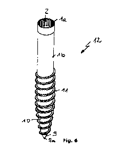
Fig. 6 a perspective representation of the finished ground
Date Recue/Date Received 2022-04-13

CA 03157846 2022-04-13
6
screw foundation.
First of all, it should be pointed out that the scale is not the
same in the individual figures.
For a method for the production of a ground screw foundation for
securing elements in the ground, first of all a cylindrical tube 1
is provided as an initial form. This tube 1 can be a drawn or
welded tube made of metal.
In the method sequence shown, the tube 1 is clamped into a flow
forming machine, not shown in any detail, and first an inner
contour 2 in the form of a spline shaft is formed in the rear end
la by means of flow forming. For this purpose, an inner mandrel 3
is inserted into the rear end la of the tube 1, which mandrel, on
its outer side, has an outer contour 4 that is complementary to
the inner contour 2. This outer contour 4 is configured in a
center region 3a of the inner mandrel 3; axially toward the left
or outside, the inner mandrel 3 has an outer region without an
outer contour, not shown, for being jointly clamped into a chuck
13 together with the rear end la of the tube 1. Axially toward the
right or inside, the inner mandrel 3 has an inner region 3b that
has a diameter that is smaller in comparison with the center
Date Recue/Date Received 2022-04-13

CA 03157846 2022-04-13
7
region 3a, so as to be able to reduce the outside diameter of the
tube 1 adjacent to the inner contour 2 of the tube 1 that is to be
formed.
After the inner mandrel 3 has been set into the rear end la of the
tube 1, two spinning rollers 5, for example, arranged symmetrically
on the circumference, are set radially against the rear end la of
the tube 1 and moved axially along the inner mandrel 3. As a
result, the inner contour 2 is formed in the tube 1, and axially
adjacent to it, a step 6 having a diameter reduction is produced on
the tube 1. In this process, of course, the spinning rollers 5 are
put into a rotational movement relative to the tube 1, i.e. either
the tube 1 is put into a rotational movement, or driven spinning
rollers 5 are used.
If this is desirable for geometrical reasons (tube lengthening)
and/or reasons of strength, the tube 1 is then elongated axially,
in that the spinning rollers 5 are moved to the right, in the
axial direction, while being radially set against the tube 1. For
this purpose, the inner mandrel 3 can be replaced by an inner
mandrel 3', which differs from the inner mandrel 3 only in that
the inner region 3b' is longer. Alternatively, elongation can also
take place without an inner mandrel.
Date Recue/Date Received 2022-04-13

CA 03157846 2022-04-13
8
In Fig. 2, the elongated region of the tube 1 that borders on the
step 6 has already been shown and identified as lb, although
Figure 2 still shows the inner mandrel 3 in engagement. In fact,
however, elongation only takes place after removal of the inner
mandrel 3 and insertion of the inner mandrel 3' (Fig. 3). In this
regard, a tailstock 7 can already have been introduced into the
open front end lc of the tube 1. This tailstock 7 can be
controlled under the effect of a spring or by machine. The
tailstock 7 serves as a support surface for the front end lc of
the tube 1, so as to produce a conically tapering region 8 by
means of radially setting the spinning rollers 5 (Fig. 3).
This conically tapering region 8 is further shaped by the spinning
rollers 5 to produce a conical front section 10 that is still open
toward the front and tapers to an insertion tip 9, for which
purpose spinning rollers 5 are pressed radially more and more
against the tube 1 in the direction toward the insertion tip 9.
Afterward or at least at the same time with the conical deformation
of the front section, a thread-like contour 11 is formed on the
front section 10 by spinning rollers 5', specifically preferably
not only on the front section 10, but rather also adjacent to the
Date Recue/Date Received 2022-04-13

CA 03157846 2022-04-13
9
cylindrical, elongated region lb of the tube 1, at least in certain
regions (Fig. 4 and 5).
In Fig. 5, the flow forming processes have been concluded, and the
tailstock 7 has been pulled out of the tube 1. For final
production of the ground screw foundation 12 for securing elements
into the ground, it is now only necessary to close off the front
end of the insertion tip 9. This is done by means of suitable
shaping, for example by means of compression, punching or folding,
and, if necessary, subsequent trimming.
The final ground screw foundation 12 is shown in Fig. 6.
Of course the invention is not restricted to the exemplary
embodiments shown. Further embodiments are possible without
departing from the basic idea. For example it is not necessary for
the inner contour 2 to be produced first; this method step can
also be carried out at a later point in time. The formation of the
thread-like contour 11 can also take place at the same time with
shaping of the front section 10, at least part of the time. The
inner contour 2 can also be formed (or pre-formed) by means of
tightening the chuck 13 while the inner mandrel 3 is inserted, at
least part of the time.
Date Recue/Date Received 2022-04-13

CA 03157846 2022-04-13
Reference Symbol List:
1 cylindrical tube
la rear end
lb elongated region
lc front end
2 inner contour
3, 3' inner mandrel
3a, 3a' center region
3b, 3b' inner region
4 outer contour
5 spinning rollers
6 step
7 tailstock
8 conically tapering region
9 insertion tip
9a front end
10 front section
11 thread-like contour
12 ground screw foundation
13 chuck
Date Recue/Date Received 2022-04-13

Representative Drawing
A single figure which represents the drawing illustrating the invention.
Administrative Status

2024-08-01:As part of the Next Generation Patents (NGP) transition, the Canadian Patents Database (CPD) now contains a more detailed Event History, which replicates the Event Log of our new back-office solution.

Please note that "Inactive:" events refers to events no longer in use in our new back-office solution.

For a clearer understanding of the status of the application/patent presented on this page, the site Disclaimer , as well as the definitions for Patent , Event History , Maintenance Fee  and Payment History  should be consulted.

Event History

Description Date
Letter Sent 2024-04-23
Request for Examination Requirements Determined Compliant 2024-04-22
All Requirements for Examination Determined Compliant 2024-04-22
Request for Examination Received 2024-04-22
Inactive: Recording certificate (Transfer) 2023-09-29
Inactive: Single transfer 2023-09-21
Letter sent 2022-05-17
Inactive: IPC assigned 2022-05-11
Inactive: First IPC assigned 2022-05-11
Priority Claim Requirements Determined Compliant 2022-05-10
Inactive: IPC assigned 2022-05-10
Application Received - PCT 2022-05-10
Request for Priority Received 2022-05-10
Inactive: IPC assigned 2022-05-10
National Entry Requirements Determined Compliant 2022-04-13
Application Published (Open to Public Inspection) 2021-04-22

Abandonment History

There is no abandonment history.

Maintenance Fee

The last payment was received on 2023-09-20

Note : If the full payment has not been received on or before the date indicated, a further fee may be required which may be one of the following

  • the reinstatement fee;
  • the late payment fee; or
  • additional fee to reverse deemed expiry.

Please refer to the CIPO Patent Fees web page to see all current fee amounts.

Fee History

Fee Type Anniversary Year Due Date Paid Date
Basic national fee - standard 2022-04-13 2022-04-13
MF (application, 2nd anniv.) - standard 02 2022-10-06 2022-08-29
MF (application, 3rd anniv.) - standard 03 2023-10-06 2023-09-20
Registration of a document 2023-09-21 2023-09-21
Request for examination - standard 2024-10-07 2024-04-22
Owners on Record

Note: Records showing the ownership history in alphabetical order.

Current Owners on Record
WINKELMANN FOUNDATION SCREW SP. Z.O.O.
Past Owners on Record
BERND RUDERT
KARL-HEINZ HECKER
RALF POTTGUTER
Past Owners that do not appear in the "Owners on Record" listing will appear in other documentation within the application.
Documents

To view selected files, please enter reCAPTCHA code :


To view images, click a link in the Document Description column. To download the documents, select one or more checkboxes in the first column and then click the "Download Selected in PDF format (Zip Archive)" or the "Download Selected as Single PDF" button.

List of published and non-published patent-specific documents on the CPD .

If you have any difficulty accessing content, you can call the Client Service Centre at 1-866-997-1936 or send them an e-mail at CIPO Client Service Centre.


Document
Description 
Date
(yyyy-mm-dd) 
Number of pages   Size of Image (KB) 
Cover Page 2022-08-17 1 50
Abstract 2022-04-13 1 18
Description 2022-04-13 10 258
Drawings 2022-04-13 3 168
Claims 2022-04-13 3 55
Representative drawing 2022-08-17 1 13
Request for examination 2024-04-22 5 143
Courtesy - Acknowledgement of Request for Examination 2024-04-23 1 437
Courtesy - Letter Acknowledging PCT National Phase Entry 2022-05-17 1 591
Courtesy - Certificate of Recordal (Transfer) 2023-09-29 1 400
International search report 2022-04-13 2 79
National entry request 2022-04-13 6 168
Amendment - Abstract 2022-04-13 2 89
Patent cooperation treaty (PCT) 2022-04-13 2 90
Declaration 2022-04-13 6 100