Note: Descriptions are shown in the official language in which they were submitted.
PTS-0015-CA
DUAL-POLARIZED ANTENNA
Field of the invention
[0001] The present invention relates to a radio frequency
(RE) module, intended to form
the passive part of a Direct Radiating Array (DRA).
Background
[0002] Antennas are elements that are used to transmit
electromagnetic signals into free
space, or to receive such signals. Simple antennas, such as dipoles, have
limited performance in
terms of gain and directivity. Parabolic antennas provide higher directivity,
but are bulky and
heavy, making them unsuitable for applications such as satellites, where
weight and volume
must be reduced.
[0003] Also known are DRA arrays that combine multiple
radiating elements (antenna
elements) that are phase shifted to improve gain and directivity. The signals
received on or
transmitted by the different radiating elements are amplified and phase
shifted between them
so as to control the shape of the receiving and transmitting lobes of the
array.
[0004] At high frequencies, for example at microwave
frequencies, the different radiating
elements are all connected via a waveguide array to a port for connecting the
antenna to an
electronic circuit comprising, for example, an RE electronic circuit and an
amplifier.
[0005] Dual polarization antennas which are capable of
transmitting or receiving signals
with two polarizations simultaneously are also known. In this case, the
signals transmitted or
received by each antenna element are combined, respectively separated,
according to their
polarization by means of a polarizer. The polarizer can also be integrated in
the antenna
element. A dual-polarized antenna has two ports for connecting each of the two
polarizations
separately respectively to and from the electronic circuit.
[0006] Such antennas for transmitting high frequencies,
especially for microwave
frequencies, are difficult to design. In particular, it is often desired to
bring the different
1
CA 03157973 2022-5-10
PTS-0015-CA
elementary antennas of the array as close together as possible in order to
reduce the amplitude
of the secondary transmission or reception lobes, in directions other than the
direction of
transmission or reception which must be favored. This reduction of the pitch
between the
different elementary antennas of the array is however incompatible with the
footprint of the
waveguide array necessary to combine the signals received by the different
elementary
antennas, respectively to divide the signals to be transmitted.
[0007] In addition, it is often necessary to reduce the
footprint of the antenna, especially
its width and height in the plane perpendicular to the direction of signal
transmission, in order
to accommodate it in the reduced volume available in a satellite or aircraft.
[0008] Another aim in designing such an antenna is to reduce its weight,
especially in space
or aeronautical applications.
[0009] Examples of known antennas are described in
W02019/226201 A2, US2011/267250
Al, W02017/053417 Al and US2017/117637 Al.
[0010] An aim is to provide an antenna suitable for the
Ka frequency band, especially for
LHCP and RHCP polarized satellite communications.
[0011] Finally, it is also desirable to produce antennas
with a new modular design that
allows the number of elementary antennas to be varied as required, without
having to redesign
the entire antenna. The design is said to be modular when different types of
antennas can be
easily designed by adding or removing standardised antenna elements during the
design of the
antenna, without having to redesign the whole antenna or waveguide array. It
is particularly
desirable to be able to design an antenna in a modular way by adding units
with several
antennas while ensuring spatial filtering.
[0012] The antenna must also, of course, have very high
efficiency gain and radiation
pattern characteristics compatible with the specifications of the application.
Finally, the antenna must be capable of being manufactured industrially and
without falling
within the scope of existing patent protection.
2
CA 03157973 2022-5-10
PTS-0015-CA
Brief summary of the invention
[0013] According to an aspect, a dual polarized antenna
(RHCP, LHCP), comprises:
at least one first port for connecting the antenna to an active circuit for
transmitting or
receiving a signal with a first polarization (LHCP);
at least one second port for connecting the antenna to an or to the active
circuit for
transmitting or receiving a signal with a second polarisation (RHCP);
a plurality of dual polarised antenna elements,
the antenna elements being arranged in cell units,
each cell unit including four antenna elements and two 1-to-4 junctions, a
first of the
two junctions being associated with a first polarisation and a second of the
two junctions being
associated with a second polarisation, each said junction comprising four
branches for
connecting to one of the polarisations of each antenna element of the
corresponding unit and a
common stub,
an array of dividers/combiners for connecting the stub of each said 1-to-4
junction of
a cell unit associated with the first polarisation with the first port and for
connecting the stub of
each said 1-to-4 junction associated with the second polarisation with the
second port,
the four antenna elements of each cell unit being superimposed,
a plurality of cell units being juxtaposed,
each cell unit comprising two antenna elements in a first plane and two other
antenna
elements in a second plane parallel to the first plane, said planes being
offset from each other
in a direction perpendicular to said planes by a distance less than the width
of an antenna
element.
[0014] This structure allows to build an array of
elementary antennas, hereafter simply
called antenna, in a modular way by juxtaposing antenna units each formed by
four elementary
antennas superimposed.
[0015] Each antenna unit has two 1-to-4 junctions and
thus enables signals to be received
and transmitted respectively according to two distinct polarizations.
[0016] Each antenna unit thus comprises four antenna
elements superimposed but shifted
two by two by two.
3
CA 03157973 2022-5-10
PTS-0015-CA
[0017] The arrangement of the antenna elements of each
unit in two planes offset from
each other in a direction perpendicular to the plane of the blade by a
distance less than the
width of an antenna element allows beamforming, or spatial filtering, of the
signals received or
transmitted within a cell unit, such that in particular directions the signals
interfere
constructively while in other directions the interference is destructive. This
beamforming at the
elementary level of each unit allows more freedom when combining antenna units
since each
antenna unit already has phase-shifted antenna pairs. It also facilitates the
connection of the
different antennas by means of the waveguide array linking the antennas
together.
[0018] The terms " superposition", " juxtaposition " or"
stacking " describe the situation of
an antenna oriented in a particular way with cell units formed by four antenna
elements
superposed on top of each other. However, it is self-evident that the antenna
can transmit and
receive independently of its orientation in space, and that the invention
relates to any antenna
which can be pivoted so that, in at least one possible orientation, the
elements/components of
the antenna are superposed, juxtaposed or stacked in the described and claimed
arrangement.
[0019] The number of antenna elements is preferably exactly four.
[0020] The array of dividers/combiners connecting the
antenna units to the ports
preferably comprises a first sub-array of dividers/combiners comprising a
stack of juxtaposed
blades. Thus, it is easily possible to make an antenna with a larger number of
antenna units by
adding additional blades and/or by increasing the number of cell units per
blade.
[0021] In each blade, the first sub-array of dividers/combiners is
arranged to connect the
stubs of each junction 1 to 4 of that blade together.
[0022] Some blades are associated with a first
polarization and other blades are associated
with the second polarization.
[0023] The first sub-array of dividers/combiners in the
blades associated with the first
polarization is arranged to connect together the stubs of junctions 1-4
associated with that first
polarization. Similarly, the first sub-array of dividers/combiners in the
blades associated with
the second polarization is arranged to connect together the stubs of junctions
1-4 associated
with that second polarization
4
CA 03157973 2022-5-10
PTS-0015-CA
[0024] The first sub-array of dividers/combiners
advantageously comprises an alternance
of first blades associated with the first polarization and of second blades
associated with the
second polarization. Thus, each blade is dedicated to a single polarization.
[0025] The antenna advantageously comprises a second sub-
array of dividers/combiners
arranged to connect said first blades to each other and to the first port, and
to connect said
second blades to each other and to the second port.
[0026] Each blade preferably extends in a first direction
substantially perpendicular to the
direction of the signal transmission, and between the two planes defined by
the extreme side
edges of the antenna elements associated with that blade.
[0027] A first blade and a second blade preferably extend between the two
planes defined
by the extreme side edges of the antenna elements associated with these two
blades. Thus, the
width of the array of dividers/combiners is less than or equal to the maximum
width of the
associated antenna elements; the total width of the antenna is thus given by
the width of the
array of elementary antennas, and it is possible to add new antenna elements
and connect
them without the array of dividers/combiners determining the total width.
[0028] The second sub-array of dividers/combiners is
advantageously provided between
said blades and said ports.
[0029] The second sub-array of dividers/combiners
preferably comprises waveguide
portions extending in a second direction substantially perpendicular to the
direction of the
signal transmission.
[0030] In an embodiment, each blade is associated with
four cell units.
[0031] Each antenna element can be connected to two
neighboring blades.
[0032] In an embodiment, the antenna comprises 32 blades,
16 associated with a first
polarization and 16 associated with the second polarization.
5
CA 03157973 2022-5-10
PTS-0015-CA
[0033] The first sub-array of dividers/combiners of each
blade has at least one bifurcation
in the H-plane.
[0034] Each antenna element preferably comprises a septum
to combine in transmission or
separate in reception the two polarizations of a radio frequency signal.
[0035] Each antenna element preferably has a square-shaped cross-section
perpendicular
to the direction of the signal propagation.
[0036] The antenna may be made in a monolithic manner.
[0037] The antenna can be made by 3D printing of a core
and deposition of a surface layer
at least on the inner side of this core.
Brief description of the figures
[0038] Examples of embodiments of the invention are shown in the
description illustrated
by the attached figures in which :
= Figure 1 shows a perspective view of an antenna comprising four cell
units
according to the invention.
= Figure 2 shows an example of a blade for connecting together the first
polarization
of four superposed cell units.
= Figure 2 shows an example of the juxtaposition of two blades designed to
connect
together the first and second polarization of four superposed cell units.
= Figure 4 illustrates a first array of dividers/combiners made up of 32
juxtaposed
blades.
6
CA 03157973 2022-5-10
PTS-0015-CA
= Figure 5 shows a 1-to-4 junction comprising four branches to be connected
to
the first polarization of the elementary antennas of a cell unit, and a stub
for the common
signal.
= Figure 6 shows a perspective view of a power combiner/divider in the H-
plane.
= Figure 7 shows a side view of a power combiner/divider in the H-
plane.
= Figure 9 shows a second array of dividers/combiners in the plane E.
= Figure 10 shows schematically how one of the polarities of the superposed
elementary antennas are connected via the associated blade.
= Figure 11 shows schematically the connections within the second array of
combiners/dividers.
Example of embodiments of the invention
[0039] The present invention relates generally to an
antenna array, referred to hereinafter
simply as an antenna, and comprising several elementary antennas 3 (radiating
elements)
arranged in a matrix such that the openings of these elementary antennas are
all in the same
plane. The direction d of the signal transmission, both in the antenna and at
the output of the
antenna, is perpendicular to this plane.
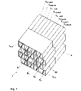
[0040] Figure 1 illustrates an antenna 1 comprising four
juxtaposed cell units 8, each cell
unit comprising four superposed elementary antennas 3. The antenna 1 of this
example thus
comprises 16 elementary antennas, numbered by row and column from 30;oto 33;3
and forming
a matrix with four rows and four columns, each column being formed in this
example by a
single cell unit. As will be seen later, the number of columns can be
increased by juxtaposing
additional cell units, and the number of rows can be increased by superposing
additional cell
units within each column.
7
CA 03157973 2022-5-10
PTS-0015-CA
[0041] The pitch between two adjacent antenna elements as
well as the pitch between
two rows is advantageously smaller than the nominal wavelength of the signal
to be
transmitted, thus reducing undesirable secondary lobes in transmission or in
reception
sensitivity.
[0042] The successive rows of the antenna are phase shifted; in the
example shown, the
even rows are phase shifted with respect to the odd rows by a pitch
corresponding to half the
width of an elementary antenna. This phase shift enables beamforming or
spatial filtering of
the signals received or transmitted by the antenna elements of the cell unit
8, so that in
particular directions the signals interfere constructively while in other
directions the
interference is destructive.
[0043] The antenna elements 3 each include an aperture
forming a radiating element
directed towards the ether, and two connection ports to the junction 5
described later. One of
the two ports is intended for a first polarization and the second is intended
for the second
polarization. The antenna includes a polarizer, preferably in the form of a
septum 32 for
separating the two polarizations LHCP and RHCP of a signal on reception
respectively for
combining the two polarizations on transmission. In another embodiment, the
antenna
elements 3 may comprise another type of polarizer, or be linked to a separate
polarizer.
[0044] The antenna 1 further comprises a series of 1-to-4
junctions 5. Two junctions 5 are
associated with each cell unit, in order on the one hand to divide
respectively combine the
LHCP first polarization signals of the four elementary antennas of the cell
unit, and on the other
hand to divide respectively combine the RHCP second polarization signals of
the four
elementary antennas of the cell unit. In this example, the number of 1-to-4
junctions is thus
equal to 8.
[0045] In the case of an antenna comprising several
superposed cell units 8, and thus more
than 4 rows, the signals at the output of the junctions 5 are combined using a
first power
divider/combiner in the H-plane, separately for each polarization. A port 7
(Figure 8) allows
each polarization to be connected to an active electronic circuit.
[0046] Figures 2 to 4 illustrate an example of a first
divider/combiner 4 with the 1-to-4
junctions of the associated cell units, in the case of a dual polarization
antenna comprising
8
CA 03157973 2022-5-10
PTS-0015-CA
16X16 antenna elements 3. The first divider/combiner consists of a number of
juxtaposed
blades 2, each blade being dedicated to one of the two polarizations LHCP or
RHCP. As each
antenna element provides two polarizations, the number of blades is therefore
equal to twice
the number of antenna elements per row, i.e. 32 blades in this example.
[0047] Each blade 2 is intended to be connected to all the antenna
elements 3 of a column,
i.e. to four cell units 8 superposed in this example. It therefore comprises
branches 5000 to
500n, each of these branches being directly connected to one of the two output
ports of one of
the antennas. Two levels of 1-to-2 junctions in the H-plane form a 1-to-4
junction (reference 5)
enabling the signals within each cell unit 8 to be combined/divided; the
signal common to the
stub 501 of the junctions in the blade 2 is combined using two further levels
of 1-to-2 junctions
in the H-plane, the signal resulting from the addition of the signals in all
the branches 500 of a
blade 2 thus ending up at the stub 23 of that blade.
[0048] Figure 2 shows a single blade 2. Figure 3 shows
two juxtaposed blades, one
dedicated to a first LHCP polarization of several superposed cell units and
the other to the
second RHCP polarization of the same cell units. Figure 4 shows the
juxtaposition of 32 blades 2
constituting the first array of dividers/combiners of the antenna.
[0049] Figure 5 illustrates a 1-to-4 junction 5 present
in each cell unit. The junction thus
comprises four branches 500 for connection to four ports of the antenna
elements 3 of a cell
unit 8. The first level comprises two 1-to-2 junctions 51 for
combining/dividing in pairs the
signals of the same polarization of two superposed antenna elements. The two
antennas of
each pair being out of phase, the junction is made in the H-plane. A second 1-
to-2 junction 50
then combines together the stubs of the two junctions 51, joined in a common
stub 501.
[0050] Figures 6 and 7 illustrate in more detail an
example of a 1-to-2 junction. This
example relates to the first power divider/combiner 21 in the first array 4;
however, the
implementation of the 1-to-2 junctions 50 and 51 in the cell units, and of the
second power
divider/combiner 22 in the first array 4 may be the same or similar, with only
the direction of
the junction branches differing. As can be seen in particular in Figure 7, the
height b1 of the
stub 201 is less than the height b2 of the portion of the junction in which
the signals combine or
divide, this height b2 being itself less than the total height b3 of the two
branches 200.
9
CA 03157973 2022-5-10
PTS-0015-CA
[0051] Figure 8 shows the rear of the antenna 1, i.e. the
side opposite the front side from
which the antenna elements 3 point. In particular, this figure shows a second
array of
dividers/combiners 6 in the [-plane, intended to combine/divide the signals
from the different
blades 2, independently for each polarization. This array 6 comprises a first
half-array 6I_HCP for
the first polarization [HG', the branches of which form a first comb intended
to be connected
to the blades 2 of the first polarization. A second half-array 6RHCp for the
second RHCP
polarization comprises branches forming a second comb interposed between the
first comb
and intended to be connected to the second polarization blades 2. The stub of
the first half
array forms the first port 7uicp of the antenna 1 and the stub of the first
half array forms the
first port 7RHCP.
[0052] Figure 9 illustrates one of the half-arrays, for
example the first half-array 6wcp. In
the illustrated example, it comprises 16 branches 600 to 60is forming the comb
intended to
connect to the stub/port of the different blades 2. The number of branches 60
is of course
dependent on the number of blades 2. Four levels of 1-to-2 junctions
61,62,63,64 in the E plane
allow the signals of these different branches to be combined/divided
successively in a common
stub 7 forming one of the two ports of the antenna. The output of this stub 7
is angled at 90 to
facilitate connection to a waveguide or directly to the electronic circuit.
[0053] Figure 10 schematically illustrates the junction
arborescence within each blade 2,
with the blade combining both the first array of dividers/combiners 4 and the
1-to-4 junctions 5
of the cell units 8 associated with that blade.
[0054] Figure 11 schematically illustrates the junction
arborescence within the second
array of dividers/combiners 6.
[0055] The antenna is advantageously made monolithically,
preferably by 3D printing of a
metal or polymer core, then deposition of a conductive layer at least on the
inner faces of the
antenna waveguides.
[0056] The above example refers to an antenna with 16X16
antenna elements. This
number is non-limiting and the number of antenna elements can be any number.
However, the
number of rows is preferably a multiple of 4 so that the antenna can be
designed by stacking
cell units with four antenna elements each. This number is also advantageously
a power of two
CA 03157973 2022-5-10
PTS-0015-CA
so that a first array of dividers/combiners 4 can be constructed with an equal
number of
junctions between each branch of this array and the stub of the blade, thus
more easily
guaranteeing paths of isophase length to the different branches.
[0057] The number of antenna elements per branch, and
thus of blades 2, can be any
number. However, this number is advantageously a power of two, so that a
second array of
dividers/combiners 6 can be made with an equal number of junctions between
each branch of
this array and the antenna ports 7, thus more easily guaranteeing isophase
length paths to the
different branches.
[0058] The antenna may have a mounting hole passing
through the array of dividers in a
direction perpendicular to the direction of signal transmission, allowing it
to be mounted by
fitting it around a cylindrical mounting rod. This solution allows the
orientation of the antenna
to be easily adjusted by pivoting it around the rod.
11
CA 03157973 2022-5-10
PTS-0015-CA
Reference numbers used in figures
1 Antenna
2 Blade
21 First power divider/combiner in the blade (H plane)
22 Second power divider/combiner in the blade (H plane)
200 Branch of a power divider/combiner in the blade
201 Stub of a power divider/combiner in the blade
23 Main stub in the blade
3 Antenna element
32 Septum
4 First array of dividers/combiners (H-plane)
1-4 junction of a cell unit
50 First power divider/combiner in the junction
51 Second power divider/combiner in the junction
500 Branch of a 1-4 junction in the cell unit
501 Stub of a 1-4 junction in the cell unit
6 Second array of dividers/combiners (plane E)
60 Connection branch between the second array of
dividers and a blade
61 First power divider/combiner in the plane E
62 Second power divider/combiner in the plane E
63 Third power divider/combiner in the plane E
64 Fourth power divider/combiner in the plane E
7 Port
8 Cell unit
LHCP Index for components related to left polarization
RHCP Index for components related to right polarization
12
CA 03157973 2022-5-10