Note: Descriptions are shown in the official language in which they were submitted.
CA 03158621 2022-04-22
WO 2021/086553
PCT/US2020/054447
RECHARGEABLE BLENDER WITH OFFSET BLADES
FIELD OF THE DISCLOSURE
[0001] The present disclosure relates to a rechargeable blender with a set
of
blades that is offset from the center.
BACKGROUND
[0002] Blenders are known, typically as consumer-grade home appliances.
Rechargeable batteries are known.
SUMMARY
[0003] One aspect of the present disclosure relates to a rechargeable
blender
with offset blades configured to blend foodstuffs. In some implementations,
the
rechargeable blender may be portable due to its size, and/or its
rechargeability. By
virtue of true portability, a user can take the blender anywhere and create
drinks,
shakes, smoothies, baby food, sauces, and/or other concoctions. Once the
blender
is fully charged, a user can prepare multiple servings quickly and easily.
Lack of an
external power source, much less a reliable external power source, is no
longer
preventing users from enjoying blended drinks. By virtue of the blades being
offset
from the center, foodstuffs are blended more efficiently. For example, ice is
crushed
more finely using fewer rotations of the blades.
[0004] The blender with offset blades may include a base assembly, a
container assembly, control circuitry, and/or other components. As used
herein, the
term "foodstuffs" may include ingredients ranging from solid to liquid, from
hot to cold
or frozen, in any combination. As used herein, the term "ingredient" merely
connotates something fit to ingest, and not necessarily nutritional value. For
example, ice and/or ice cubes may be ingredients.
[0005] As used herein, any association (or relation, or reflection, or
indication,
or correspondency) involving assemblies, blades, motors, rotational axes,
longitudinal axes, diameters, batteries, couplings, interfaces, buttons,
detectors,
indicators, magnetic elements, caps, rotations, and/or another entity or
object that
interacts with any part of the blender and/or plays a part in the operation of
the
- 1 -
CA 03158621 2022-04-22
WO 2021/086553
PCT/US2020/054447
blender, may be a one-to-one association, a one-to-many association, a many-to-
one association, and/or a many-to-many association or N-to-M association (note
that
Nand M may be different numbers greater than 1).
[0006] As used herein, the term "effectuate" (and derivatives thereof) may
include active and/or passive causation of any effect. As used herein, the
term
"determine" (and derivatives thereof) may include measure, calculate, compute,
estimate, approximate, generate, and/or otherwise derive, and/or any
combination
thereof.
[0007] These and other features, and characteristics of the present
technology, as well as the methods of operation and functions of the related
elements of structure and the combination of parts and economies of
manufacture,
will become more apparent upon consideration of the following description and
the
appended claims with reference to the accompanying drawings, all of which form
a
part of this specification, wherein like reference numerals designate
corresponding
parts in the various figures. It is to be expressly understood, however, that
the
drawings are for the purpose of illustration and description only and are not
intended
as a definition of the limits of the invention. As used in the specification
and in the
claims, the singular form of "a", "an", and "the" include plural referents
unless the
context clearly dictates otherwise.
BRIEF DESCRIPTION OF THE DRAWINGS
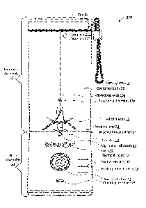
[0008] FIG. 1 shows a front view of a rechargeable blender with offset
blades
configured to blend foodstuffs, in accordance with one or more
implementations.
[0009] FIG. 2 shows a side view of a rechargeable blender with offset
blades
configured to blend foodstuffs, in accordance with one or more
implementations.
[0010] FIG. 3 shows an isometric elevated view of a rechargeable blender
with offset blades configured to blend foodstuffs, in accordance with one or
more
implementations.
[0011] FIG. 4A shows a top view of a rechargeable blender with offset
blades
configured to blend foodstuffs, in accordance with one or more
implementations.
[0012] FIG. 4B shows a bottom view of a rechargeable blender with offset
blades configured to blend foodstuffs, in accordance with one or more
implementations.
- 2 -
CA 03158621 2022-04-22
WO 2021/086553
PCT/US2020/054447
[0013] FIG. 5 shows a front view of a base assembly of a rechargeable
blender with offset blades configured to blend foodstuffs, in accordance with
one or
more implementations.
[0014] FIG. 6 shows a side view of a base assembly of a rechargeable
blender with offset blades configured to blend foodstuffs, in accordance with
one or
more implementations.
[0015] FIG. 7 shows a top view of a base assembly of a rechargeable
blender
with offset blades configured to blend foodstuffs, in accordance with one or
more
implementations.
[0016] FIG. 8 shows an isometric elevated view of a base assembly of a
rechargeable blender with offset blades configured to blend foodstuffs, in
accordance with one or more implementations.
[0017] FIG. 9 shows a front view of a rechargeable blender with offset
blades
configured to blend foodstuffs, with an indication for a cross-sectional view,
in
accordance with one or more implementations.
[0018] FIG. 9A shows a cross-sectional view of a rechargeable blender with
offset blades configured to blend foodstuffs, as indicated in FIG. 9, in
accordance
with one or more implementations.
[0019] FIG. 10 shows a front view of a container body of a rechargeable
blender with offset blades configured to blend foodstuffs, in accordance with
one or
more implementations.
[0020] FIG. 11 shows a side view of a container body of a rechargeable
blender with offset blades configured to blend foodstuffs, in accordance with
one or
more implementations.
[0021] FIG. 12 shows a rear view of a container body of a rechargeable
blender with offset blades configured to blend foodstuffs, in accordance with
one or
more implementations.
[0022] FIG. 13 shows a top view of a container body of a rechargeable
blender with offset blades configured to blend foodstuffs, in accordance with
one or
more implementations.
- 3 -
CA 03158621 2022-04-22
WO 2021/086553
PCT/US2020/054447
[0023] FIG. 14 shows an isometric elevated view of a container body of a
rechargeable blender with offset blades configured to blend foodstuffs, in
accordance with one or more implementations.
[0024] FIG. 15A shows a front view of a cap of a rechargeable blender with
offset blades configured to blend foodstuffs, in accordance with one or more
implementations.
[0025] FIG. 15B shows an isometric elevated view of a cap of a
rechargeable
blender with offset blades configured to blend foodstuffs, in accordance with
one or
more implementations.
[0026] FIG. 150 shows a bottom view of a cap of a rechargeable blender
with
offset blades configured to blend foodstuffs, in accordance with one or more
implementations.
DETAILED DESCRIPTION
[0027] FIG. 1 shows a rechargeable blender 100 with offset blades
(hereinafter blender 100) configured to blend foodstuffs, in accordance with
one or
more implementations. Blender 100 may include one or more of a base assembly
11, a container assembly 12, control circuitry 17 (depicted in FIG. 1 as a
dotted
rectangle to indicate this component may be embedded within base assembly 11,
and not readily visible from the outside), and/or other components. Base
assembly
11 and container assembly 12 may be configured to be coupled during blending
by
blender 100. For example, in some implementations, base assembly 11 and
container assembly 12 may be mechanically coupled, e.g., through one or more
threaded couplings. Other types of couplings may be envisioned for blender
100,
though leak-proof options may be preferred, since most uses include one or
more
liquid ingredients. In some implementations, control circuitry 17 and/or other
components may be included in base assembly 11, e.g., within base assembly 11.
For example, one or more of control circuitry 17, electrical motor 14,
rechargeable
battery 15, and/or other components may be integrated permanently into base
assembly 11 such that base assembly 11 forms an integral whole.
[0028] Base assembly 11 may include one or more of a base body llb (FIG.
6), a set of blades 13 (also referred to as a set of one or more blades 13),
an
electrical motor 14 (depicted in FIG. 1 as a dotted rectangle to indicate this
- 4 -
CA 03158621 2022-04-22
WO 2021/086553
PCT/US2020/054447
component may be embedded within base assembly 11), a rechargeable battery 15
(depicted in FIG. 1 as a dotted rectangle to indicate this component is
embedded
within base assembly 11), a standardized charging interface 25, one or more
mechanical couplings 16, a detector 18, one or more alignment indicators 19, a
power interface 29, a logo 27 (which may visually refer to a corporate
identity),
and/or other components.
[0029] Proximal end 21 of container assembly 12 may be disposed near set
of
blades 13 during blending of blender 100. Distal end 22 of container assembly
12
may be disposed opposite proximal end 21.
[0030] In some implementations, one or more mechanical couplings 16 may
include threaded couplings. By way of non-limiting example, FIG. 2 shows a
side
view of blender 100 with offset blades configured to blend foodstuffs. For
example,
one or more mechanical couplings 16 may include a first mechanical coupling
16a
and a second mechanical coupling 16b. In some implementations, first
mechanical
coupling 16a included in base assemble 11 may be a female threaded coupling
configured to fit together with second mechanical coupling 16b of container
assembly 12. First mechanical coupling 16a and second mechanical coupling 16b
may be configured to (temporarily and detachably) couple base assembly 11 to
container assemble 12.
[0031] Second mechanical coupling 16b of container assembly 12 may be
disposed at or near proximal end 21 of container assembly 12. Second
mechanical
coupling 16b may be configured to engage first mechanical coupling 16a to
couple
base assembly 11 to container assembly 12. In some implementations, first
mechanical coupling 16a and second mechanical coupling 16b may be threaded
couplings. In some implementations, first mechanical coupling 16a and second
mechanical coupling 16b may have parallel threads.
[0032] By way of non-limiting example, FIG. 3 shows an isometric elevated
view of blender 100 depicting its cylindrical shape. By way of non-limiting
example,
FIG. 4A shows a top view of blender 100 depicting cap 24. By way of non-
limiting
example, FIG. 4B shows a bottom view of blender 100 depicting the bottom of
base
assembly 11.
- 5 -
CA 03158621 2022-04-22
WO 2021/086553
PCT/US2020/054447
[0033] Referring to FIG. 1, set of blades 13 may be rotatably mounted to
base
assembly 11 to blend foodstuffs. Set of blades 13 may be configured to rotate
around a rotational axis 13a. Rotational axis 13a is depicted in FIG. 1 as a
geometric 2-dimensional line extending indefinitely through set of blades 13,
and is
not a physical axis. Rather, rotational axis 13a indicates how set of blades
13
rotates in relation to other components of blender 100, in a rotational
direction 13b.
In some implementations, set of blades 13 may be mounted permanently to base
assembly 11. In some implementations, set of blades 13 may be disposed at or
near
proximal end 21 of container assembly 12 during blending by blender 100. In
some
implementations, set of blades 13 may include 1, 2, 3, 4, 5, or more pairs of
blades.
In some implementations, a pair of blades may include two blades on opposite
sides
of rotational axis 13a. In some implementations, a pair of blades may have two
blades such that the distal ends of these two blades are at the same
horizontal level.
In some implementations, as depicted in the upright configuration of blender
100 in
FIG. 1, set of blades 13 may include six blades that form 3 pairs of blades.
In some
implementations, set of blades 13 may include at least two downward blades,
which
may prevent and/or reduce foodstuffs remaining unblended when disposed under
the upward blades. In some implementations, set of blades 13 may include at
least
four upward blades. In some implementations, including six blades may be
preferred
over including less than six blades, in particular for blending ice and/or ice
cubes. By
using more blades, more points of contact will hit the ice at substantially
the same
time, which reduces the likelihood that a piece of ice is merely propelled
rather than
broken, crushed, and/or blended, in particular for implementations having
limited
power (when compared to common outlets), such as disclosed herein. As used
herein, directional terms such as upward, downward, left, right, front, back,
and so
forth are relative to FIG. 1 unless otherwise noted.
[0034] Referring to FIG. 1, in some implementations, base assembly 11 may
have a cylindrical shape (apart from set of blades 13). By way of non-limiting
example, FIGs. 5-6-7-8 shows different views of base assembly 11 of blender
100
that depict base assembly 11 as having a cylindrical shape. For example,
horizontal
cross-sections of base assembly 11 may have a circular shape. In some
implementations, the cylindrical shape of base assembly 11 may have a diameter
- 6 -
CA 03158621 2022-04-22
WO 2021/086553
PCT/US2020/054447
between 2 and 4 inches, which may be referred to as a base diameter. In some
implementations, the cylindrical shape of base assembly 11 may have a base
diameter between 3 and 3.5 inches. Such a base diameter may improve
portability,
as well as allow blender 100 to be stored in a cup holder, e.g., in a vehicle.
For
example, FIG. 5 shows a front view of base assembly 11, depicting a blade
diameter
13d (e.g., the diameter of the circle described by rotation of the distal ends
of the
lowest pair of blades in set of blades 13) and a base diameter lla (as
measured at
or near the top of base assembly 11). In some implementations, blade diameter
13d
may refer to the largest diameter of any circle described by rotation of
distal ends of
pairs of blades in set of blades 13, as measured perpendicular to rotation of
set of
blades 13. In some implementations, the orientation of blade diameter 13d may
be
orthogonal to the direction of rotational axis 13a. In some implementations,
the
plane of rotation of the distal ends of the blades that define blade diameter
13d may
be orthogonal to the direction of rotational axis 13a. In some
implementations, blade
diameter 13d may be at least 50% of base diameter 11a. In some
implementations,
blade diameter 13d may be about 60% of base diameter 11a. In some
implementations, blade diameter 13d may range between 50% and 70% of base
diameter 11a. In some implementations, blade diameter 13d may range between
60% and 70% of base diameter 11a. In some implementations, blade diameter 13d
may range between 60% and 80% of base diameter 11a. FIG. 5 shows set of
blades 13 may be supported by a shaft 13c mounted on an upper blade mount 13e.
FIGs. 7 and 8 show a lower blade mount 13f arranged below upper blade mount
13e. Below lower blade mount 13f is a surface 13g. In some implementations,
surface 13g may form the lowest point for foodstuffs during blending. By
virtue of the
stepwise structure formed by upper blade mount 13e, lower blade mount 13f, and
surface 13g, foodstuffs may be blended more efficiently. For example, ice may
be
crushed more finely using fewer rotations of the blades. In some
implementations,
the horizontal plane that coincides with the top surface of upper blade mount
13e
may be orthogonal to rotational axis 13a. Alternatively, and/or
simultaneously, in
some implementations, the horizontal plane that coincides with the top surface
of
lower blade mount 13f may be orthogonal to rotational axis 13a. Alternatively,
and/or
simultaneously, in some implementations, the horizontal plane that coincides
with
- 7 -
CA 03158621 2022-04-22
WO 2021/086553
PCT/US2020/054447
surface 13g may be orthogonal to rotational axis 13a. In some implementations,
the
plane of rotation of the distal ends of the blades that define blade diameter
13d may
be parallel to one or more of the top surface of upper blade mount 13e, the
top
surface of lower blade mount 13f, and/or surface 13g.
[0035] In some implementations, set of blades 13 may be mounted
permanently on base assembly 11 such that base assembly 11 forms an integral
whole. In some implementations, base assembly 11 may have a conical shape,
wherein the bottom of the conical shape may have a diameter between 2 and 4
inches, and wherein the top of the conical shape may have a diameter between 2
and 4 inches. For example, the bottom of base assembly 11 may be wider than
the
top of base assembly 11, as depicted in FIG. 5.
[0036] Referring to FIG. 1, container assembly 12 may include one or more
of
a proximal end 21, a distal end 22, a container body 20, a second mechanical
coupling 26, a cap 24, a coupling 24a, a carrying strap 3, and/or other
components.
Container body 20 may form a vessel to hold and/or contain foodstuffs within
container assembly 12. In some implementations, container body 20 may be a
cylindrical body and/or have a cylindrical shape, as depicted in different
views in
FIGs. 10-14. In some implementations, the dimensions of container assembly 12
may be such that the internal volume of container assembly 12 can hold 8, 10,
12,
14, 16, 18, 20, 22, 24, 28, 32, 36, 48, or more ounces. In some
implementations,
container assembly 12 and/or container body 20 may have cylindrical shapes. As
shown in FIG. 11, in some implementations, the cylindrical shapes of container
assembly 12 and/or container body 20 may have a container diameter 20d between
2 and 4 inches (as measured at or near the bottom of container body 20). In
some
implementations, container body 20 may have a container diameter 20e at or
near
second mechanical coupling 16b. In some implementations, container diameter
20d
and/or container diameter 20e may be between 3 and 3.5 inches. In some
implementations, container body 20 may be transparent. Referring to FIG. 11,
in
some implementations, second mechanical coupling 16b may be a male threaded
coupling configured to fit together with first mechanical coupling 16a of base
assembly 11 (in FIG. 8). In some implementations, coupling 24a may be a
threaded
coupling configured to fit together with cap 24. In some implementations,
blade
- 8 -
CA 03158621 2022-04-22
WO 2021/086553
PCT/US2020/054447
diameter 13d (see FIG. 5) may be at least 50% of container diameter 20d (FIG.
11).
In some implementations, blade diameter 13d may be about 60% of container
diameter 20d. In some implementations, blade diameter 13d may range between
50% and 70% of container diameter 20d. In some implementations, blade diameter
13d may range between 60% and 70% of container diameter 20d. In some
implementations, blade diameter 13d may range between 60% and 80% of container
diameter 20d. Alternatively, and/or simultaneously, in some implementations,
blade
diameter 13d (see FIG. 5) may be at least 50% of container diameter 20e (FIG.
11).
In some implementations, blade diameter 13d may be about 60% of container
diameter 20e. In some implementations, blade diameter 13d may range between
50% and 70% of container diameter 20e. In some implementations, blade diameter
13d may range between 60% and 70% of container diameter 20e. In some
implementations, blade diameter 13d may range between 60% and 80% of container
diameter 20e.
[0037] Referring to FIG. 1, electrical motor 14 may be configured to
rotationally drive set of blades 13. In some implementations, electrical motor
14 may
operate at a voltage between 5V and 10V. In one or more preferential
implementations, electrical motor 14 may operate at a voltage of about 7.4V.
In
some implementations, electrical motor 14 may be configured to spin set of
blades
13 at a maximum speed between 20,000 rotations per minute (RPM) and 35,000
RPM. In one or more preferential implementations, electrical motor 14 may spin
set
of blades 13 at a maximum speed of about 22,000 RPM. Electrical motor may be
configured to be powered by rechargeable battery 15. Simultaneously, in some
implementations, electrical motor 14 may be further configured to be powered
through standardized charging interface 25, though that may not be the
preferred
way of operating blender 100. In one or more preferential implementations, no
power is (or need be) supplied to electrical motor 14 from an external power
source
during blending by blender 100. In some implementations, control circuit 17
may be
configured to control electrical motor 14 during rotation of set of blades 13.
For
example, control circuit 17 may control the speed of the rotation of set of
blades 13
during blending by blender 100.
- 9 -
CA 03158621 2022-04-22
WO 2021/086553
PCT/US2020/054447
1-0038.1 By way of non-limiting example, FIG. 9 shows a front view of
blender
100 with an indication for a cross-sectional view labeled "A-A", and FIG. 9A
shows a
cross-sectional view 100a of blender 100 labeled "SECTION A-A" as indicated in
FIG. 9. FIG. 9A shows the position and arrangement of electrical motor 14 in
relation to set of blades 13 and rotational axis 13a. As depicted, electrical
motor 14
and set of blades 13 are offset from being centered within blender 100. The
front of
blender 100 is depicted on the right-hand side in FIG. 9A, illustrating that
electrical
motor 14 and set of blades 13 are offset towards the back of blender 100.
1-0039.1 By way of non-limiting example, FIG. 6 shows a side view of base
assembly 11 of blender 100 in a manner that depicts the position and
arrangement
of set of blades 13 and rotational axis 13a in relation to the rest of base
assembly 11.
In particular, the cylindrical shape of base body llb may have a longitudinal
axis
100b, which is a geometric 2-dimensional line extending indefinitely through
base
assembly 11 (and/or blender 100). Longitudinal axis 100b is not a physical
axis.
Instead, the shape of base assembly 11 (particularly base body 11b) may be
symmetrical around longitudinal axis 100b. In some implementations,
longitudinal
axis 100b may coincide with the center line through base body llb from top to
bottom. FIG. 6 shows an offset 13x between rotational axis 13a and
longitudinal axis
100b. Set of blades 13 is offset towards the back of base assembly 11. In some
implementations, electrical motor 14 is offset towards the back of base
assembly 11,
e.g., by a similar offset distance as used for positioning set of blades 13.
In some
implementations, offset 13x may be between 5% and 15% of container diameter
20d
(FIG. 11). In some implementations, offset 13x may be between 8% and 12% of
container diameter 20d (FIG. 11). In some implementations, offset 13x may be
between 5% and 15% of container diameter 20e (FIG. 11). In some
implementations, offset 13x may be between 10% and 20% of container diameter
20e (FIG. 11). In some implementations, offset 13x may be between 5% and 15%
of
blade diameter 13d (FIG. 5). In some implementations, offset 13x may be
between
10% and 14% of blade diameter 13d (FIG. 5). In some implementations, offset
13x
may be between 15% and 20% of blade diameter 13d (FIG. 5). In some
implementations, offset 13x may be between 20% and 40% of blade diameter 13d
(FIG. 5). In some implementations, offset 13x may be between 5% and 40% of
- 10-
CA 03158621 2022-04-22
WO 2021/086553
PCT/US2020/054447
blade diameter 13d (FIG. 5). In some implementations, offset 13x may be
between
5% and 15% of base diameter lla (FIG. 5). In some implementations, offset 13x
may be between 10% and 20% of base diameter lla (FIG. 5). In some
implementations, offset 13x may be between 20% and 40% of base diameter lla
(FIG. 5). In some implementations, offset 13x may be between 5% and 40% of
base
diameter 11 a (FIG. 5).
[0040] Referring to FIG. 1, rechargeable battery 15 may be configured to
power electrical motor 14. In some implementations, rechargeable battery 15
may
be configured to power electrical motor 14 such that, during blending by
blender 100,
no power is supplied to electrical motor 14 from an external power source. In
some
implementations, rechargeable battery 15 may be non-removable. As used herein,
the term "non-removable" may mean not accessible to users during common usage
of blender 100, including charging, blending, cleaning, and storing for later
use. In
some implementations, rechargeable battery 15 may be not user-replaceable. In
some implementations, rechargeable battery 15 may have a capacity between 1000
mAh and 6000 mAh. In one or more preferential implementations, rechargeable
battery 15 may have a capacity of about 2500 mAh. In some implementations,
control circuit 17 may be configured to control charging of rechargeable
battery 15.
For example, control circuit 17 may control the transfer of electrical power
through
standardized charging interface 25 into rechargeable battery 15. For example,
responsive to a detection that rechargeable battery 15 is fully charged,
control circuit
17 may prevent the transfer of electrical power through standardized charging
interface 25 into rechargeable battery 15.
[0041] Standardized charging interface 25 may be configured to conduct
electrical power to rechargeable battery 15. In some implementations,
standardized
charging interface 25 may be configured to conduct electrical power to charge
rechargeable battery 15, e.g., from an external power source. In some
implementations, standardized charging interface 25 may be configured to
support
wireless charging of rechargeable battery 15, e.g., from an external power
source,
including but not limited to induction-based charging. In some
implementations,
standardized charging interface 25 may be a universal serial bus (USB) port
configured to receive an electrical connector for charging rechargeable
battery 15.
-11 -
CA 03158621 2022-04-22
WO 2021/086553
PCT/US2020/054447
In such a case, the electrical connector may be connected to an external power
source. In some implementations, standardized charging interface 25 may be
covered for protection and/or other reasons.
[0042] Detector 18 may be configured to detect whether first mechanical
coupling 16a of base assembly 11 is engaged with second mechanical coupling
16b
of container assembly 12. In some implementations, detector 18 may be
configured
to detect whether base assembly 11 is coupled to container assembly 12 in a
manner operable and suitable for blending by blender 100. In some
implementations, operation of detector 18 may use one or more magnetic
elements.
For example, in some implementations, one or more magnetic elements are
included
in container body 20 at or near proximal end 21 of container assembly 12.
Engagement may be detected responsive to these one or more magnetic elements
being aligned and sufficiently close to one or more matching magnetic elements
that
may be included in base assembly 11 (e.g., at or near first mechanical
coupling 16a
of base assemble 11).
[0043] Power interface 29 may be part of the user interface of blender
100.
Power interface 29 may be configured to be engaged manually by the user, for
example by pushing power interface 29 to turn blender 100 on and off. In some
implementations, control by a user of blender 100 may be based on a switch
(not
shown), a button, a touchscreen (not shown), voice-controlled operation (not
shown),
gesture-based operation (not shown), and/or other types of user interfaces
suitable
to turn consumer appliances on and off. Power interface 29 may be configured
to
illuminate in various colors (red, blue, etc.) and/or patterns (solid, fast
blinking, slow
blinking, alternating red and blue, etc.). Power interface 29 may convey
information
regarding the operational status of blender 100 to a user. The operation
status of
blender 100 may be determined by control circuitry 17. Power interface 29 may
be
controlled by control circuitry 17. For example, if power interface 29 is
solid red,
blender 100 may be charging and/or insufficiently charged to blend. For
example, if
power interface 29 is solid blue, blender 100 may be ready for blending. For
example, if power interface 29 is alternating red and blue, blender 100 may
not be
ready for blending due to base assembly 11 and container assembly 12 not being
coupled properly and/or fully. For example, in some implementations, threaded
- 12-
CA 03158621 2022-04-22
WO 2021/086553
PCT/US2020/054447
couplings between assembly 11 and container assembly 12 may need to be
tightened sufficiently for proper blending, and power interface 29 may warn
the user
when the treaded couplings are not tightened sufficiently. In some
implementations,
power interface 29 may include a power button configured to be manually
engaged
by the user.
[0044] Control circuitry 17 may be configured to control different
functions
and/or operations of blender 100, including but limited to turning blender 100
on and
off, charging of rechargeable battery 15, controlling of electrical motor 14
regarding
and/or during rotation of set of blades 13, determining whether mechanical
couplings
16 are engaged properly for blending, controlling operation of power interface
29,
and/or performing other functions for blender 100. In some implementations,
control
circuitry 17 may be configured to prevent rotation of set of blades 13
responsive to a
determination that mechanical couplings 16 are not engaged (or not engaged
properly for the intended operation of blender 100). In some implementations,
control circuitry 17 may be configured to control power interface 29 to convey
information regarding the operational status of blender 100 to a user. For
example,
power interface 29 may include a light that can illuminate in various colors
and/or
patterns. In some implementations, control circuitry 17 may be implemented as
a
printed circuit board (PCB).
[0045] Referring to FIG. 1, cap 24 may be disposed at or near distal end 22
of
container assembly 12. In some implementations, cap 24 may be removable. For
example, removing cap 24 may create an opening at distal end 22 of container
assembly 12. In some implementations, blended foodstuffs may be removed
through this opening, e.g., by pouring. By way of non-limiting example, FIG.
15A
illustrates a front view of cap 24, FIG. 15B shows an isometric elevated view
of cap
24, and FIG. 15C shows a bottom view of cap 24. In some implementations, cap
24
may include a threaded coupling 27b that is configured to engage with
container
body 20 (as shown in FIG. 1 and FIG. 4). In some implementations, the
combination
of cap 24 and filter 27 may include a threaded coupling that is configured to
engage
with container body 20. In some implementations, cap 24 may include a spout,
indentation, and/or other shape of its structure that may be used to pour
and/or drink
- 13 -
CA 03158621 2022-04-22
WO 2021/086553
PCT/US2020/054447
from. For example, such an opening may be coverable during blending of blender
100.
[0046] Referring to FIG. 1, in some implementations, coupling 24a of
container assembly 12 may be configured to removably couple cap 24 to
container
body 20 and/or other components of container assembly 12. In some
implementations, coupling 24a may be a threaded coupling. In some
implementations, coupling 24a may have a parallel thread.
[0047] Referring to FIG. 1, carrying strap 3 may be configured to carry
blender
100. In some implementations, carrying strap 3 may be attached to cap 24 as
depicted in FIG. 1. Alternatively, in some implementations, carrying strap 3
may be
attached to container assembly 12, e.g., to container body 20.
[0048] Although the present technology has been described in detail for
the
purpose of illustration based on what is currently considered to be the most
practical
and preferred implementations, it is to be understood that such detail is
solely for
that purpose and that the technology is not limited to the disclosed
implementations,
but, on the contrary, is intended to cover modifications and equivalent
arrangements
that are within the spirit and scope of the appended claims. For example, it
is to be
understood that the present technology contemplates that, to the extent
possible,
one or more features of any implementation can be combined with one or more
features of any other implementation.
- 14-