Note: Descriptions are shown in the official language in which they were submitted.
SYRINGE FOR POWERED POSITIVE DISPLACEMENT PIPETTE
TECHNICAL FIELD
[0001] Exemplary embodiments of the general inventive concept are
directed to a
handheld powered positive displacement pipette and pipette assembly, including
novel
syringes for said pipette, and associated mechanisms for the releasable
retention,
ejection, and possible automatic identification of said syringes.
BACKGROUND
[0002] As would be understood by one of skill in the art, pipettes are
generally of either
air displacement or positive displacement design. In contrast to an air
displacement
pipette in which a cushion of air separates aspirated liquid from the pipette
piston, a
positive displacement pipette is designed for direct contact between the
pipette piston and
the aspirated liquid.
[0003] The positive displacement pipette design eliminates potential air
displacement
pipette inaccuracies that may result from the effects of different liquid
properties and/or
environmental conditions on the air cushion of the air displacement pipette.
For example,
altitude changes, evaporation and other conditions to which an air
displacement pipette
may be subjected can affect air displacement pipette accuracy.
[0004] While a positive displacement pipette can provide the aforementioned
advantages over an air displacement pipette, known positive displacement
pipettes have
their own shortcomings. One such shortcoming has traditionally been the
inability of
known positive displacement pipettes to provide accurate, non-contact
dispensing of very
small liquid volumes, including volumes below 1 pl. More specifically, when
dispensing
very small liquid volumes using known positive displacement pipettes there Is
a tendency
for some amount of liquid to adhere to the inside of the pipette tip after the
dispensing
stroke, which then requires subsequent physical contact ("touch-off") of the
pipette tip with
the liquid receiving vessel to discharge said adhering liquid from the pipette
tip.
[0005] Additionally, direct contact between the piston of a positive
displacement
pipette and the liquid of interest during normal use means that the piston
cannot be
reused. Consequently, positive displacement pipettes typically use a
"consumable" in the
form of a disposable syringe that includes not only a hollow barrel
(capillary) with a tip
portion, but also a piston that resides and seals within the capillary and is
reciprocatable
within the capillary by the pipette to aspirate and dispense a desired amount
of a liquid of
Date recue/Date Received 2023-09-27
CA 03158788 2022-04-22
WO 2021/081531 PCT/US2020/057420
interest while the capillary and piston are releasably attached to the
pipette. After the
pipetting operation is complete, the entire syringe is normally removed from
the positive
displacement pipette and discarded.
[0006]
The complexity associated with the insertion, retention and ejection of a
positive
displacement pipette syringe is greater than that associated with a typical
air displacement
pipette tip, which is far more simplistic in construction and commonly held in
place on the
dispensing end of an air displacement pipette body by mere friction. In a
positive
displacement pipette, the syringe must be securely retained on the pipette
body until
deliberately ejected, while the piston is simultaneously properly positioned
within the
pipette for releasable engagement and reciprocation by an
aspiration/dispensing
mechanism of the pipette.
[0007]
There is an existing need for a positive displacement pipette that can provide
accurate and repeatable non-contact dispensing of various volumes of liquid,
including
very small liquid volumes. There is also an existing need for a positive
displacement
pipette having an improved mechanism by which syringes may be easily and
reliably
installed to, releasably retained by, and ejected from the pipette. Exemplary
positive
displacement pipettes according to the general inventive concept, and various
features of
said exemplary positive displacement pipettes, satisfy these needs.
SUMMARY
[0008] An exemplary embodiment of a handheld, powered positive displacement
pipette according to the general inventive concept will generally include a
substantially
hollow body that is preferably shaped for ergonomic gripping by a user and
acts as a
housing for the various internal components of the pipette. A proximal end of
the body
may include a user interface portion, while a distal end of the body is
configured for and
serves as the connection end for a syringe.
[0009]
An exemplary pipette will generally further include a motorized drive
assembly,
a dispensing solenoid assembly, a syringe retention mechanism, a syringe
piston
grasping mechanism, and a syringe ejection mechanism, all of which are housed
within
the pipette body. At least some of the aforesaid components may further reside
within an
internal housing that is also located within the pipette body.
[0010]
A syringe is releasably installed to the distal end of the pipette for
aspirating
and dispensing fluids of interest. Syringes may be provided in a number of
different
2
CA 03158788 2022-04-22
WO 2021/081531 PCT/US2020/057420
volumes. Regardless of the volume, however, each syringe generally includes a
generally
hollow external barrel (capillary) that may be of tubular shape, or some other
shape such
as but not limited to an elliptical or obround shape. The capillary includes a
tip with an
orifice at its distal end, and functions to contain a fluid specimen to be
dispensed. At a
top of each capillary resides a syringe retention element, which may be an
integral part of
the capillary. The shape and dimension of the syringe retention elements
cooperates with
the syringe retention mechanism of the pipette.
[0011] Each syringe also includes a piston having a first, fluid-
contacting portion that
is arranged within the capillary, and a piston head that is connected thereto
and resides
io proximally of the syringe retention element when the piston is located
in the capillary. The
piston head is configured for releasable engagement with a piston carrier of
the syringe
piston grasping mechanism of the pipette.
[0012] The motorized drive assembly is responsible for setting various
positions of the
syringe attached to the pipette, for drawing the syringe piston toward the
proximal
is direction of the pipette to aspirate fluid into the syringe, for moving
the syringe piston in a
distal direction to dispense fluid from the syringe, and for producing a
syringe-ejecting
movement.
[0013] The dispensing solenoid assembly includes an armature that floats
within a
bore in a solenoid body and is linearly displaceable relative thereto. The
armature includes
20 a shaft that extends through an opening in the solenoid body and
connects the armature
to the piston carrier, which forms a portion of the syringe piston retention
mechanism of
the pipette and is engaged with the piston head of the syringe piston.
[0014] The dispensing solenoid assembly and the syringe piston grasping
mechanism reside substantially within a piston carriage, which is coupled to
the output
25 of a drive motor of the motorized drive assembly by a lead screw. In one
exemplary
embodiment, operation of the drive motor may rotate a drive nut that is
engaged with the
lead screw but restrained from linear displacement, thereby transferring the
rotational
output of the motor into a linear displacement of the lead screw and piston
carriage, and
of components such as the dispensing solenoid that are coupled to the piston
carriage.
30 In another exemplary embodiment, operation of the drive motor may rotate
the lead
screw within a drive nut that is linearly displaceable but rotationally
restrained, thereby
transferring the rotational output of the motor into a linear displacement of
the lead
3
CA 03158788 2022-04-22
WO 2021/081531 PCT/US2020/057420
screw, the piston carriage and various components coupled to the piston
carriage. In
other exemplary embodiments, the lead screw and or drive nut may be replaced
with
other components that result in a desired, controlled displacement of the
piston carriage
and various components coupled to the piston carriage.
[0015] The dispensing solenoid assembly of an exemplary pipette is
configured to,
depending on the selected dispensing volume and dispensing mode, produce a
pulsed
dispensing of a selected volume of fluid on its own or to assist the motorized
drive
assembly with the dispensing function by ensuring that all of each selected
dispensing
volume is actually dispensed from the syringe without the need to touch-off
the syringe tip
against a sample-receiving vessel. More specifically, energizing the solenoid
body (coil)
produces a rapid and forceful displacement of the solenoid armature toward the
distal end
of the pipette, thereby causing a like rapid movement of the piston carrier
and syringe
piston, and expelling a jet of fluid from the syringe tip. The general concept
of pulsed fluid
dispensing relative to a bench top pipette instrument may be reviewed in
European Patent
Application EP1344565A1. The displacement of the piston carriage followed by
an
actuation of the dispensing solenoid assembly can be repeated as desired to
dispense
multiple aliquots each representing a fraction of the entire liquid volume
held by the
syringe.
[0016] Operation of the motorized drive assembly and the dispensing
solenoid
assembly is governed by a controller that receives instruction signals from
user inputs
and/or from internal programming. The controller also receives position
information
signals from an encoder.
[0017] A selected syringe is securely but releasably retained on the
pipette by the
syringe retention mechanism and the syringe piston is coupled to the solenoid
armature
via the piston carrier of the syringe piston grasping mechanism as well as to
the motorized
drive system.
[0018] Once an aspiration and dispensing operation is complete, the
syringe ejection
mechanism is operative to decouple the syringe retention element of the
syringe from the
syringe retention mechanism and to decouple the syringe piston head from the
piston
carrier. The motorized drive system then drives the piston carriage toward the
distal end
of the pipette which, via release elements associated with the piston
carriage, causes the
syringe retention mechanism to release the syringe capillary and the syringe
piston
4
CA 03158788 2022-04-22
WO 2021/081531 PCT/US2020/057420
grasping mechanism to disengage from the syringe piston head, whereafter the
syringe
will be automatically ejected from the pipette.
[0019] Various dispensing operations using an exemplary pipette may be
accomplished in an automatic mode or via a manual mode. A user is able to
access and
selectively initiate a desired automatic pipetting program through the user
interface portion
of the pipette.
[0020] Auto mode dispensing may encompass a number of different and selectable
dispensing procedures. These dispensing procedures may result, for example: in
aspiration of a full syringe volume of fluid, followed by dispensing of the
entirety of the
io aspirated fluid volume in one dispensing operation; in aspiration of
some volume of fluid
into the syringe, followed by dispensing of the aspirated fluid in multiple
doses of equal
volume; in aspiration of some volume of fluid into the syringe, followed by
dispensing of
the aspirated fluid in multiple doses of variable volume; or in aspiration of
some volume
of fluid into the syringe, followed by dispensing of the aspirated fluid in
multiple doses of
is equal or variable volume until some portion (e.g., 50%) of the aspirated
volume has been
dispensed, and then performing another aspiration operation. A dispensing
operation
may also be performed by a user in a manual mode rather than by the controller
of the
pipette operating in auto mode.
[0021] Performance of a titration procedure may also be possible. A
titration program
20 of an exemplary pipette may include a titrated volume counter that
indicates the volume
of titrant that has been dispensed, and the counter may be resettable to allow
for multiple
titration operations from a single aspirated volume of titrant.
[0022] An exemplary pipette may also include fluid viscosity detection
capability, such
as by, for example and without limitation, providing the pipette with
appropriate circuitry
25 or other means for monitoring an increase in current draw of the
motorized drive assembly
motor required to move the syringe piston relative to the syringe capillary
during an
aspiration or dispensing operation; through use of a provided load cell that
measures the
force required to move the syringe piston relative to the syringe capillary
during an
aspiration or dispensing operation; by way of a mechanical spring; or via
another
30 technique that would be understood by one of skill in the art. The value
of the current
draw may be used to categorize the viscosity of the fluid, and the pipette
controller may
5
CA 03158788 2022-04-22
WO 2021/081531 PCT/US2020/057420
adjust the dispensing operation parameters of the pipette based on the
identified fluid
viscosity category.
[0023] An exemplary pipette may be further provided with an automatic
syringe
identification system. Such a system would allow the controller of the pipette
to
automatically select the appropriate operating parameters for the given
syringe volume,
thereby simplifying the setup process and possibly eliminating operator error
associated
with mistakenly identifying the volume of a syringe being used. Such a system
may be
effectuated, for example, by associating each syringe volume with a different
color,
placing an area of corresponding color on the syringe, locating in the pipette
a color sensor
that is configured and located to image the colored areas on the syringes, and
transmitting
imaging data from the color sensor to the pipette controller. The signal to
the pipette
controller is indicative of the color of the colored area on the syringe, and
the controller is
programmed to analyze the signal and to resultingly identify the volume of the
installed
syringe.
[0024] An exemplary pipette according to the general inventive concept is
able to
accurately and repeatably dispense fluid doses of sub-microliter volume
through volumes
of milliliters or more. The ability to automatically dispense selected volumes
of fluids of
interest without the need to touch off the syringe tip means that the
dispensing operation
is also user independent, and therefore insulated from possible user-
introduced error.
These are significant improvements over the capabilities of known positive
displacement
pipettes.
[0025] Other aspects and features of the general inventive concept will
become
apparent to those of skill in the art upon review of the following detailed
description of
exemplary embodiments along with the accompanying drawing figures.
BRIEF DESCRIPTION OF THE DRAWINGS
[0026] In the following descriptions of the drawings and exemplary
embodiments, like
reference numerals across the several views refer to identical or equivalent
features, and:
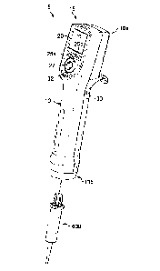
[0027] FIG. 1 is a perspective view of an exemplary embodiment of a
motor-driven
positive displacement pipette according to the general inventive concept, and
includes a
syringe shown prior to insertion into the pipette;
[0028] FIG. 2 shows an assembly of the exemplary pipette of FIG. 1 with
the syringe
installed into and retained by the pipette;
6
CA 03158788 2022-04-22
WO 2021/081531 PCT/US2020/057420
[0029] FIG. 3 is enlarged view of a user end of the exemplary pipette of
FIGS. 1-2;
[0030] FIG. 4 represents an exemplary user interface provided on the
user end of an
exemplary pipette according to the general inventive concept;
[0031] FIG. 5A is cross-sectional side view of the exemplary pipette
assembly of FIG.
2, with various internal components of the pipette and a piston of the syringe
shown in an
aspirating position;
[0032] FIG. 5B is an enlarged transparent view of a portion of the
pipette of FIG. 5A;
[0033] FIGS. 6A-6B are a perspective view and a cross-sectional side
view,
respectively, of an exemplary 0.1m1 syringe for use with an exemplary
inventive pipette;
[0034] FIGS. 7A-7B are a perspective view and a cross-sectional side view,
respectively, of an exemplary 1.0m1 syringe for use with an exemplary
inventive pipette;
[0035] FIGS. 8A-8B are a perspective view and a cross-sectional side
view,
respectively, of an exemplary 10m1 syringe for use with an exemplary inventive
pipette;
[0036] FIGS. 9A-9B are a perspective view and a cross-sectional side
view,
respectively, of an exemplary 25m1 syringe for use with an exemplary inventive
pipette;
[0037] FIGS. 10A-10B are a perspective view and a cross-sectional side
view,
respectively, of an exemplary 50m1 syringe for use with an exemplary inventive
pipette;
[0038] FIG. 11 is a cross-sectional side view of the exemplary pipette
of FIG. 1A, with
a housing portion of the pipette removed to better reveal various internal
components of
the pipette;
[0039] FIG. 12 is an enlarged, cross-sectional perspective view of
various internal
drive components of the exemplary pipette of FIG. 11;
[0040] FIG. 13 is an enlarged, cross-sectional view of a distal portion
of an exemplary
motor-driven positive displacement pipette, showing various internal
components that
form an exemplary syringe retention mechanism;
[0041] FIG. 14A is a perspective view and FIGS. 14B-14C are elevation
views of a
piston carrier element of an exemplary syringe piston grasping mechanism;
[0042] FIG. 15A is a deconstructed view showing the piston head of an
exemplary
syringe inserted into the piston carrier element of FIGS. 14A-14C, with
certain piston
release elements of an exemplary syringe ejection mechanism also present;
[0043] FIG. 15B is a slightly less deconstructed view of FIG. 15A, with
additional
elements of an exemplary syringe ejection mechanism also present;
7
CA 03158788 2022-04-22
WO 2021/081531 PCT/US2020/057420
[0044] FIG. 16 indicates how an exemplary syringe is inserted into an
exemplary
motor-driven positive displacement pipette;
[0045] FIG. 17A is an enlarged view showing the syringe and pipette of
FIG. 16 with
the syringe partially inserted into the pipette such that the piston head of
the syringe is
only partly engaged by the piston head grasping mechanism of the pipette;
[0046] FIG. 17B is an enlarged view showing the syringe and pipette of
FIG. 17A with
the syringe inserted farther into the pipette but not yet fully engaged by the
syringe
retention mechanism thereof;
[0047] FIG. 18 shows the syringe and pipette of FIG. 17 with the syringe
fully inserted
into the pipette, such that the syringe is engaged by the syringe retention
mechanism of
the pipette and a piston head of the syringe is engaged by the syringe piston
grasping
mechanism of the pipette;
[0048] FIG. 19 is an enlarged, cross-sectional view of a portion of FIG.
18 showing the
interaction of various components of the syringe retention mechanism and the
syringe
piston grasping mechanism with elements of the syringe;
[0049] FIGS. 20A-20D illustrate various components of an exemplary
syringe ejection
mechanism of an exemplary motor-driven positive displacement pipette;
[0050] FIG. 21A illustrates the position of the various syringe ejection
mechanism
components of FIGS. 20A-20D along with other associated components of the
pipette
shortly after initiation of a syringe ejection operation;
[0051] FIGS. 21B-21E further illustrate the position of the various
syringe ejection
mechanism components of FIGS. 20A-20D as a syringe ejection operation
progresses;
[0052] FIG. 21F represents the retractive movement of a piston carrier
portion of the
pipette during a last phase of an exemplary syringe ejection operation;
[0053] FIG. 22 is an enlarged cross-sectional side view of a portion of an
exemplary
motor-driven positive displacement pipette showing the various internal
components
thereof when the pipette is in a home position;
[0054] FIGS. 23A-23B are cross-sectional side views of an exemplary
motor-driven
positive displacement pipette with attached syringe according to the general
inventive
concept, and illustrate the change in position of various internal components
of the pipette
and the syringe piston when the pipette is moved from the home position to a
ready to
fully aspirated position, such as might result from a fluid aspiration
operation;
8
CA 03158788 2022-04-22
WO 2021/081531 PCT/US2020/057420
[0055] FIG. 24 depicts the change in position of various internal
components of the
exemplary pipette and syringe assembly from the fully aspirated position shown
in FIG.
23B during one exemplary type of fluid dispensing operation; and
[0056] FIG. 25 is a bottom perspective view of an exemplary motor-driven
positive
displacement pipette where a color sensor is visible along with various other
components.
DETAILED DESCRIPTION OF THE EXEMPLARY EMBODIMENTS
[0057] FIG. 1 depicts one exemplary embodiment of a handheld, motor-
driven positive
displacement pipette 5 (hereinafter "pipette" for brevity) according to the
general inventive
concept. Also shown in FIG. 1 is a consumable in the form of an exemplary
disposable
io syringe 600 (see FIGS. 8A-8B) that is installed to the pipette in order
to perform a pipetting
operation. Various exemplary syringes for use with exemplary inventive
pipettes are
shown in FIGS. 6A-10B and described in more detail below. FIG. 2 shows an
assembly
of the pipette 5 and syringe 600 of FIG. 1.
[0058] The exemplary pipette 5 of FIGS. 1-2 includes a body 10 for
gripping by a user.
is The body 10 is generally a substantially hollow structure that also
serves as an external
housing for various internal components of the pipette 5. The body 10 may be
of different
shape and/or size in other embodiments, although the shape and size will
typically be
dictated to at least some extent by the ergonomics of use.
[0059] The body 10 further includes a proximal (user) end 10a and distal
end 10b that
20 serves as the connection end for the syringe 600. In this example, the
proximal end 10a
of the body 10 includes a user interface portion 15. Referring also to FIGS. 3-
4, it may be
observed that the user interface portion 15 of this exemplary pipette 5
further includes a
display 20 and various actuators such as input/selection buttons 25a, 25b, and
a joystick
27 that allow a user to observe and select pipette functions, observe and
change pipette
25 settings and engage in various other interactions with a programmable
controller of the
pipette, as would be understood by one of skill in the art. In this exemplary
embodiment
of the pipette 5, a trigger switch 30 is also provided for initiating pipette
operation, and an
eject button 32 is provided for initiating a syringe ejection operation.
[0060] FIG. 5A is a cross-sectional side view of the exemplary pipette 5
and syringe
30 600 assembly of FIG. 2, which reveals the various internal components of
the pipette that
are concealed by the body 10. As may be observed, the exemplary pipette 5
includes,
among other components, a motorized drive assembly 40, a dispensing solenoid
9
CA 03158788 2022-04-22
WO 2021/081531 PCT/US2020/057420
assembly 250, a syringe retention mechanism 150 and syringe piston grasping
mechanism 200, all of which are described in more detail below. The assembly
of FIG.
5A also includes the syringe 600, which is releasably retained by the syringe
retention
mechanism 150 of the pipette 5 and is shown in a post-aspiration and pre-
dispensing
position. An enlarged and transparent view of a portion of the proximal end
10a of the
pipette body 10 is shown in FIG. 5B, and reveals additional pipette components
such as
a printed circuit board and various electronic components, including motor
control circuitry
comprising a controller 90.
[0061] A variety of exemplary syringes that are usable with an exemplary
pipette
io according to the general inventive concept are represented in the
perspective and cross-
sectional elevation views of FIGS. 6A-10B. The exemplary syringes 500-600 are
arranged in order of increasing of volume, with FIGS. 6A-6B representing an
exemplary
syringe 500 having a volume of 0.1m1, FIGS. 7A-7B representing an exemplary
syringe
550 having a volume of 1.0m1, FIGS. 8A-8B representing an exemplary syringe
600
is having a volume of 10m1, FIGS. 9A-9B representing an exemplary syringe
650 having a
volume of 25m1, and FIGS. 10A-10B representing an exemplary syringe 700 having
a
volume of 50m1. Thus, while the exemplary syringe 600 of FIGS. 8A-8B has been
arbitrarily selected as the syringe component of an exemplary pipette and
syringe
assembly for purposes of illustration, it should be understood that an
exemplary inventive
20 pipette is usable with a number of different syringes to accurately and
repeatably dispense
samples across a wide volume range.
[0062] Each of the exemplary syringes 500, 550, 600 shown in FIGS. 6A-8B
includes
an external barrel, referred to herein as a capillary 505, 555, 605, which is
of generally
hollow and tubular construction and functions to contain the fluid specimen to
be
25 dispensed. A distal end of each capillary 505, 550, 605 includes a tip
510, 560, 610
having an orifice 515, 565, 615 through which fluid previously aspirated into
the capillary
may be dispensed. A top of each capillary 505, 555, 605 forms a syringe
retention
element 520, 570, 620 of like shape and dimension. The shape and dimension of
the
syringe retention elements 520, 570, 620 allows for engagement thereof by the
syringe
30 retention mechanism 150 located in the pipette 5. For example, in
particular syringe
embodiments shown, each syringe retention element 520, 570, 620 includes a
CA 03158788 2022-04-22
WO 2021/081531 PCT/US2020/057420
circumferential edge 535, 585, 635 and a lower face 540, 590, 640 that may be
engaged
by elements of the syringe retention mechanism 150.
[0063] Each syringe 500, 550, 600 also includes a piston 525, 575, 625
(sometimes
also referred to as a plunger) having a first, fluid-contacting portion that
is concentrically
arranged within the capillary 505, 555, 605 for aspirating and dispensing
fluid, a head 530,
580, 630 portion that resides proximally of the syringe retention element 520,
570, 620,
and a connecting portion that passes through an aperture in the syringe
retention element
to connect the piston head with the fluid-contacting portion. The piston heads
530, 580,
630 of the exemplary syringes 500, 550, 600 shown herein are substantially
bell-shaped,
and include opposing arms 530a-530b, 580a-580b, 630a-630b that permit at least
some
degree of elastic deformation thereof. Other piston head shapes and other
numbers of
arms may be possible in other embodiments.
[0064] When a syringe 500, 550, 600 is properly installed to the pipette
5, the syringe
is retained in a stationary position by engagement of the syringe retention
element 520,
570, 620 of the syringe and the syringe retention mechanism 150 of the
pipette, and a
head 530, 580, 630 portion of the piston 525, 575, 625 is engaged by the
piston grasping
mechanism 200 of the pipette, such that the fluid-contacting portion of the
piston is
reciprocatable within the capillary 505, 555, 605 by the pipette. The syringes
500, 550,
600 are ejectable from the pipette 5 after use, as described in more detail
below.
[0065] The exemplary syringes 650, 700 shown respectively in FIGS. 9A-9B
and 10A-
10B are designed for use in the pipetting of larger fluid volumes. In these
exemplary
syringe embodiments, a capillary 655, 705 having a tip 660, 710 with an
orifice 665, 715
is again included, and a piston 670, 720 is again arranged to reciprocate
within the
capillary. However, unlike the exemplary syringe embodiments 500, 550, 600
depicted in
FIGS. 6A-8B, the capillaries 655, 705 of the syringes 650, 700 have open tops
(proximal
ends) and do not include a syringe retention element. Instead, each syringe
650, 700
includes a reusable adaptor 675, 725 for connecting the syringe to the pipette
5.
[0066] Each adaptor 675, 725 has an open distal end that is dimensioned
to receive
the proximal end of the syringe 650, 700. Retention elements at the proximal
end of the
capillary 655, 705 and in the distal end of the adaptor 675, 725 cooperate to
secure the
capillary to the adaptor. The proximal end of the adaptor 675, 725 forms a
syringe
retention element 680, 730 that is shaped and dimensioned to engage with the
syringe
11
CA 03158788 2022-04-22
WO 2021/081531 PCT/US2020/057420
retention mechanism in the pipette 5. For example, in particular syringe
embodiments
shown, each syringe retention element 680, 730 includes a circumferential edge
690, 740
and a lower face 695, 745 that may be engaged by elements of the syringe
retention
mechanism 150.
[0067] Each syringe 650, 700 includes a piston 620, 720 having a first,
fluid-contacting
portion that is concentrically arranged within the capillary 655, 705 for
aspirating and
dispensing fluid, a head 685, 735 portion that resides proximally of the
syringe retention
element 680, 730 of the adaptor 675, 725, and a connecting portion that passes
through
an aperture in the syringe retention element to connect the piston head with
the fluid-
contacting portion. The piston heads 685, 735 of the exemplary syringes 650,
700 shown
herein are again substantially bell-shaped, and include opposing arms 685a-
685b, 735a-
735b that permit at least some degree of elastic deformation thereof. Other
piston head
shapes and other numbers of arms may be possible in other embodiments.
[0068] When a large volume syringe 650, 700 is properly installed to the
pipette 5, the
syringe is retained in a stationary position by engagement of the syringe
retention element
680, 730 of the adaptor 675, 725 and the syringe retention mechanism 150 of
the pipette,
and the piston head 685, 735 is engaged by the piston grasping mechanism 200
of the
pipette, such that the fluid-contacting portion of the piston is
reciprocatable within the
capillary 655, 705 by the pipette. The syringes 650, 700 are ejectable from
the pipette 5
after use, as described in more detail below.
[0069] It is to be understood that the syringes of FIGS. 6A through FIG.
10B have been
provided for purposes of illustration only, and variations are certainly
possible. For
example, and without limitation, the piston head and the piston of a given
syringe may be
separate, engageable elements, rather than integral parts of a single element
as shown
ad described herein.
[0070] Likewise, although only the exemplary larger volume syringes 650,
700 of
FIGS. 9A-10B are shown and described as employing an adapter with an open-top
capillary, it is equally possible that the smaller volume syringes 500, 550,
600 of FIGS.
6A-8B may be of a like design and also include an adapter. When a given
syringe includes
an adapter, the adapter may be a reusable component rather than a consumable
component as will be the remainder of the syringe in most syringe embodiments.
12
CA 03158788 2022-04-22
WO 2021/081531 PCT/US2020/057420
[0071] A cross-sectional side view of the exemplary pipette 5 of FIG. 1
is illustrated in
FIG. 11, with the body 10 thereof removed to better reveal the various
internal
components of the pipette. As briefly described above, the pipette 5 can be
seen to
include a motorized drive assembly 40 at a proximal end, a syringe retention
mechanism
150 at a distal end, and a dispensing solenoid assembly 250 and a syringe
piston grasping
mechanism 200 interposed therebetween. The pipette 5 also includes an internal
housing
35 that contains each of the dispensing solenoid assembly 250, the syringe
piston
grasping mechanism 200 and the syringe retention mechanism 150. The motorized
drive
assembly 40 is attached to a proximal end of the internal housing 35.
io [0072] The motorized drive assembly 40 is responsible for setting
various positions of
the syringe 600 attached to the pipette 5, for moving the syringe piston in a
distal-to-
proximal direction to aspirate fluid into the syringe, for moving the syringe
piston in a
proximal-to-distal direction to dispense fluid from the syringe, and for
producing the
movement necessary to eject the syringe. Referring also to FIG. 12, it may be
observed
is that in this exemplary pipette 5, the motorized drive assembly 40
includes a drive motor
45 having its output shaft coupled to a rotatable drive nut 50 by a drive belt
55, whereby
rotation of the drive nut by the drive motor causes a linear displacement of a
lead screw
95 that passes through the drive nut and is in threaded engagement herewith.
Other drive
schemes may be utilized in other embodiments, such as for example, a direct
drive
20 scheme where the output of the drive motor is connected to the lead
screw 95 directly by
a coupling, or possibly through a speed reduction gear assembly.
[0073] In this exemplary motorized drive assembly 40, the drive belt 55
may connect
an output pinion 60 affixed to the output shaft of the motor 45 to an input
pinion 65 that is
coupled to or integral to the drive nut 50. The drive nut 50 may be provided
with bearings
25 70 to facilitate rotation of the drive nut, and the drive nut may also
be preloaded with a
spring 75 (e.g., wave spring) that will bias the drive nut toward the proximal
end of the
pipette 5 to help account for any manufacturing (e.g., stack-up) tolerance
variations within
the motorized drive assembly 40 and to minimize backlash that may otherwise
contribute
to inaccuracies during a dispensing operation. A mounting block 80 or a
similar
30 structure/component may be provided to facilitate mounting of the
various components of
the motorized drive assembly 40.
13
CA 03158788 2022-04-22
WO 2021/081531 PCT/US2020/057420
[0074] The dispensing solenoid assembly 250 is configured to, depending
on the
selected dispensing volume, dispense the selected volume of fluid on its own
or to assist
the motorized drive assembly 40 with the dispensing function by ensuring that
all of a
selected dispensing volume is actually dispensed from the syringe 600 without
the need
to touch the syringe tip 610 to the sample-receiving vessel (as explained
below). The
dispensing solenoid assembly 250 includes a solenoid body (coil) 255 that
resides within
and is coupled to the piston carriage 100, such that the solenoid body moves
axially with
the piston carriage. The solenoid body 255 includes an axial bore 270 that
extends some
distance into the solenoid body from the axial end thereof. An armature 260 is
io concentrically located within the bore 270 and is linearly
reciprocatable within the bore
and relative to the pipette 5 by a magnetic field that is generated within the
bore, as would
be understood by one of skill in the art. As the armature 260 floats within
the bore 270 as
opposed to being coupled to the piston carriage 100 like the solenoid body
255, the
armature is not constrained (for some distance) to move linearly with the
piston carriage.
is A bottom wall of the bore 270 acts as an armature hard stop 275 during
proximal-to-distal
movement of the armature 260. In the exemplary dispensing solenoid assembly
250
shown, the armature 260 includes a shaft 265 that extends through an opening
in a bottom
wall of the bore 270 toward the distal end of the pipette 5.
[0075] Operation of the motorized drive assembly 40 and the dispensing
solenoid
20 assembly 250 is governed by the controller 90 (see FIG. 5B). The
controller 90 receives
instruction signals from user inputs such as the actuators, 25, 30 and/or from
internal
programming. The controller 90 also receives position information signals from
an
encoder 85 that is coupled to the drive nut 50.
[0076] Rotational motion of the drive nut 50 is converted to linear
(axial) motion by the
25 lead screw 95 that passes through the drive nut and is in threaded
engagement therewith.
Whereas the drive nut 50 is freely rotatable, the lead screw 95 is
rotationally constrained
but linearly displaceable. Thus, rotation of the drive nut 50 by the drive
motor 45 will
cause the lead screw 95 to move in a proximal or distal direction along the
longitudinal
axis of the pipette 5.
30 [0077] The distal end 95b of the lead screw 95 is attached to a
proximal end of a piston
carriage 100 in a manner that prevents rotation of the lead screw 95. The
piston carriage
100 is located in a carriage holder 105 that is mounted within the internal
housing 35 so
14
CA 03158788 2022-04-22
WO 2021/081531 PCT/US2020/057420
as to be restrained from movement relative thereto. The piston carriage 100 is
axially
displaceable and reciprocatable within the carriage holder 105, and relative
to the
longitudinal axis of the pipette 5, but is rotationally restrained.
[0078] The dispensing solenoid assembly 250 and the syringe piston
grasping
mechanism 200 (both described in detail below) reside substantially within the
piston
carriage 100. Therefore, both the dispensing solenoid assembly 250 and the
syringe
piston grasping mechanism 200 move with the piston carriage 100 during linear
displacement of the piston carriage within the pipette 5.
[0079] For proper pipetting, the syringe 600 must be securely retained
on the pipette
5 and the motorized drive system 40 of the pipette 5 must be coupled to the
syringe piston
625 to reciprocate the syringe piston within the syringe capillary 605. These
syringe
retention and piston coupling functions are respectively performed by the
exemplary
syringe retention mechanism 150 and syringe piston grasping mechanism 200 of
the
pipette 5.
[0080] A better understanding of the exemplary syringe retention mechanism
150 of
the pipette 5 may be obtained by additional reference to FIG 13, which
provides an
enlarged cross-sectional view of the distal end of the exemplary pipette 5.
The exemplary
syringe retention mechanism 150 is shown to include a plurality of spaced
apart syringe
latching elements 155 that are affixed within the distal end of the pipette 5,
such as by a
pinned connection 185 to the body 10 (see, e.g., FIG. 20C), so as to be
pivotable within
some rotational range of motion but restrained against axial movement. In this
exemplary
pipette 5, there are three syringe latching elements 155 (only two visible in
FIG. 11), but
a different number of latching elements may be utilized in other embodiments.
[0081] The syringe latching elements 155 of the syringe retention
mechanism 150 are
shown in a closed position in FIG. 11, and are maintained in a normally closed
position
by an elastic 0-ring 160 or similar elastic element that encircles the three
syringe latching
elements 155 and resides within a slot 165 provided in each latching element.
The syringe
latching elements 155 are coupled to the piston carrier 205 using a mounting
pin 185 (see
FIG. 200), which allows the syringe latching mechanisms to pivot during a
syringe
insertion procedure as will be more fully explained below.
[0082] Each syringe latching element 155 of the syringe retention
mechanism 150 also
includes a latching hook 170 at its distal end. The latching hooks 170 of the
syringe
CA 03158788 2022-04-22
WO 2021/081531 PCT/US2020/057420
latching elements 155 are designed to engage the syringe retention element on
the
syringe capillary when the syringe is inserted into the distal end of the
pipette 5. For
example, with respect to the arrangement of the pipette 5 and the syringe 600
shown in
FIG. 5, the latching hooks 170 of the syringe latching elements 155 are
designed to
engage the syringe retention element 620 (e.g., along the lower face 640) on
the syringe
capillary 605.
[0083] While the syringe retention mechanism 150 secures the capillary
of the syringe
600 to the pipette 5 and maintains the capillary in a stationary position
relative thereto,
the syringe piston grasping mechanism 200 engages and releasably retains the
head 630
io of the syringe piston 625. To this end, the syringe piston grasping
mechanism 200
includes a piston carrier 205 that is located substantially within the piston
carriage 100.
As may be observed in more detail in FIGS. 14A-14C, at least the internal
shape of the
piston carrier 205 may substantially conform to the external shape of the
syringe piston
head 630. The exemplary piston carrier 205 further includes a distally located
actuation
is collar 285 having a piston head retention lip 210, and a plurality of
radially spaced apart
apertures 215 that permit access through the wall of the piston carrier to the
arms 630a,
630b of the piston head 630 by piston head release elements 305 of an
exemplary syringe
ejection mechanism, as further described below.
[0084] A plurality of spaced apart piston head release element guides
220 extend
20 .. transversely outward from the actuation collar 285 of the piston carrier
205. As may be
observed (see also FIGS. 17A-17B and 21A-21E), the inwardly-directed face 220a
of
each piston head release element guide 220 has a ramped (cammed) shape that
directs
movement of a distal portion of a corresponding one of the piston head release
elements
305 during a syringe ejection operation. The outwardly-directed surface 220b
of each
25 piston head release element guide 220 may facilitate axial movement of
the piston carrier
205 within the internal housing 35 and/or may function to rotationally
restrain the piston
carrier.
[0085] A proximal end 205a of the piston carrier 205 is configured to
facilitate coupling
of the piston carrier to a distal end of the armature shaft 265 of the
dispensing solenoid
30 .. assembly 250. Thus, in an assembled pipette 5, the piston carrier 205 is
reciprocatable
along with the piston carriage 100 by the motorized drive assembly 40, and is
further
16
CA 03158788 2022-04-22
WO 2021/081531 PCT/US2020/057420
independently reciprocatable within the piston carriage by the dispensing
solenoid
assembly 250.
[0086] A better understanding of the operation of the piston carrier 205
may be
obtained by reference to the deconstructed views of FIGS. 15A-15B. FIG. 15A
shows the
exemplary syringe 600 with the piston head 630 thereof inserted into the
piston carrier
205 of FIGS. 13 and 14A-14C, with the piston head release elements 305 of the
exemplary syringe ejection mechanism pivotably located in the apertures 215 in
the piston
carrier. The piston head 630 preferably fits snugly within the interior of the
piston carrier
and, as may be observed, distal ends of the piston head arms 630a, 630b are
engaged
with the piston head retention lip 210 in the piston carrier 205, thereby
preventing
withdrawal of the piston head 630 from the piston carrier. Consequently, the
piston head
630 is securely grasped by the piston carrier 205 and it is ensured that the
piston 625 of
the syringe 600 will move axially along with any axial movement of the piston
carrier.
[0087] Referring now to FIGS. 16-17B, the process of inserting the
exemplary syringe
600 to the exemplary pipette 5 may be observed. FIG. 16 shows the syringe 600
located
below the distal end of the pipette 5 and in substantial axial alignment
therewith. The
arrow indicates the direction of engaging movement of the syringe 600 toward
the pipette
5.
[0088] In FIG. 17A, the syringe 600 has been partially inserted into the
pipette 5.
During insertion of the syringe 600, the piston head 630 of the syringe piston
625 begins
engagement with the piston carrier 205 of the syringe piston grasping
mechanism 200. It
may be observed in FIG. 17A that, during the syringe insertion process, the
piston head
arms 630a, 630b of the piston head 630 are inwardly compressed (i.e., undergo
an
inwardly-directed elastic deformation) via contact with a wall formed by the
distal opening
290 in the actuation collar 285 of the piston carrier 205. The inward
compression of the
piston head arms 630a, 630b allows the syringe piston head 630 to pass through
the distal
opening in the actuation collar 285.
[0089] FIG. 17B depicts partial engagement of the syringe 600 and the
pipette 5
resulting from continued insertion of the proximal end of the syringe 600 into
the distal
end of the pipette 5 beyond the point shown in FIG. 17A. Such continued
insertion of the
syringe 600 results in an outward pivotal movement of the distal ends of the
syringe
latching elements 155 under the insertion force applied to the syringe 600.
More
17
CA 03158788 2022-04-22
WO 2021/081531 PCT/US2020/057420
specifically, as the syringe 600 is inserted into the pipette 5, a resulting
outwardly-directed
force is exerted on the distal ends of the syringe latching elements 155 by
the syringe
retention element 620, which force is sufficient to overcome the inwardly-
directed force
exerted on the syringe latching elements by the 0-ring 160.
[0090] As insertion of the syringe 600 into the pipette 5 continues, a
proximal (upper)
face of the syringe retention element 620 of the syringe capillary 605 comes
into abutting
contact with one or more springs 300 that are retained within the pipette 5.
As may be
observed in FIG. 17B, at the point of contact between the proximal (upper)
face of the
syringe retention element 620 and the spring(s) 300, the syringe retention
element 620
has preferably moved past the latching hooks 170 of the syringe latching
elements 155
(although a slight compression of the spring(s) may alternatively be required
to reach said
point), which permits the syringe latching elements 155 to be returned to
their normally-
closed positions by the contractive force of the 0-ring 160. Upon return of
the syringe
latching elements 155 to their normally closed positions (see also FIGS. 18-
19), a flat 175
on each syringe latching element hook 170 overlies and engages the lower face
640 of
the syringe retention element 620 while an inward-facing surface 180 of each
syringe
latching element 155 is preferably pressed against the circumferential edge
635 of the
syringe retention element by the contractive spring force of the 0-ring 160.
The syringe
capillary 605 is thereby trapped against and releasably locked to the pipette
5, meaning
that the syringe capillary is also securely retained in a stationary position
relative to the
pipette.
[0091] Subsequent to the releasable locking of the syringe 600 to the
pipette 5, as
shown in FIG. 17B and described above, the continued application of an
insertion force
on the syringe results in a slight but additional proximally-directed movement
of the
syringe into the pipette. This additional movement of the syringe 600 results
from
compression of the spring(s) 300 in the pipette by the insertion force being
exerted on the
syringe.
[0092] As illustrated in FIG. 18, the additional proximal movement of
the syringe 600
into the pipette 5 allows the piston head 630 of the syringe to become fully
inserted into
the piston carrier, whereafter the piston head arms 630a, 630b will
elastically return
toward their normal static positions and become engaged with the piston head
retention
lip 210 located in the actuation collar 285 of the piston carrier, as shown in
FIG. 18. The
18
CA 03158788 2022-04-22
WO 2021/081531 PCT/US2020/057420
engagement of the piston head arms 630, 630b with the actuation collar 285
retains the
piston head 630 in the piston carrier 205. It may also be observed in FIG. 18
that the
piston head 630 fits snugly within the interior of the piston carrier 205 in
this exemplary
embodiment of the pipette 205.
[0093] In FIGS. 18-19, the syringe 600 is fully installed to the pipette 5.
In the fully
installed position, the syringe 600 is releasably locked to the pipette 5 as
described above,
and the piston head of the syringe is fully engaged by the syringe piston
grasping
mechanism 200 of the pipette. The syringe 600 is usable to aspirate and
dispense fluids
once placed in the fully installed position shown.
[0094] In addition to providing for additional insertion of the syringe 600
into the pipette
5 after the syringe retention element 620 of the syringe capillary 605 has
reached an
engaged position with the syringe retention mechanism 150 of the pipette, the
spring(s)
300 also provides for increased retention security and stationary engagement
of the
syringe 600 to the pipette 5. More specifically, with the syringe 600
installed to the pipette
5, the spring(s) 300 exerts a distally-directed force against the upper face
of the syringe
retention element 620, which presses the lower face 640 of the syringe
retention element
tightly against the flats 175 of the hooks 170 of the syringe latching
elements 155. The
distally-directed force exerted by the spring(s) 300 also urges the piston
head 630 toward
the distal end of the pipette 5, which presses the distal ends of the piston
head arms 630a,
630b tightly against the piston head retention lip 210 in the actuation collar
285 portion of
the piston carrier 205. Therefore, any possible unintended movement of the
syringe
retention element 620 relative to the syringe latching elements 155 of the
syringe retention
mechanism 150 and/or movement of the piston head 630 relative to the piston
carrier 205
is discouraged by the axially-directed force exerted by the spring(s) 300,
thereby further
securing the syringe 600 to the pipette 5. The spring(s) 300 may be, for
example and
without limitation, a sheet metal spring(s). The use of other types of springs
may also be
possible.
[0095] Because a positive displacement pipette syringe is disposable ¨
i.e., intended
to be discarded subsequent to completion of an associated pipetting operation
¨ the
exemplary syringe 600 must be ejectable from the pipette 5. As may be best
understood
from a review of the deconstructed perspective views of FIGS. 20A-20D and the
cross-
sectional views of FIGS. 21A-21F (see also FIGS 13, 15A-15B, and 17A-19) the
pipette
19
CA 03158788 2022-04-22
WO 2021/081531 PCT/US2020/057420
is provided with an exemplary syringe ejection mechanism for this purpose.
Generally
speaking, the syringe ejection mechanism is operative to decouple the syringe
retention
element 620 of the syringe 600 from the syringe retention mechanism 150 and to
decouple
the syringe piston head 630 from the piston carrier 205, whereafter the
syringe will be
5 automatically ejected from the pipette 5. As is explained in more detail
below, the syringe
ejection mechanism of the exemplary pipette 5 is comprised generally of the
motorized
drive assembly 40 and the lead screw 95, the piston carriage 100 and the wedge-
shaped
syringe latching element release portions 335 thereof, the syringe latching
elements 155,
the piston head release element guides 220 on the actuation collar portion 285
of the
io piston carrier 205, and a plurality of piston head release elements 305.
[0096] FIG. 20A essentially provides the same view of the piston head
630 of the
exemplary syringe 600 inserted into the piston carrier 205 that is shown in
FIG. 15A,
except that in FIG. 20A the piston carrier 205 has been removed for further
clarity. It may
be observed in FIG. 20A that the piston head release elements 305 (which are
shown to
is .. be aligned with the apertures 215 in the piston carrier 205 in FIG. 15A)
of the syringe
ejection mechanism are arranged to at least partially overlie the opposing
arms 630a,
630b of the syringe piston head 630 when the piston head is inserted into the
piston carrier
205. Each of the exemplary piston head release elements 305 may include a
roller 310
at its distal end. The rollers 310 function to reduce friction between the
piston head
20 release elements 305 and the inwardly-directed ramped face 220a of each
piston head
release element guide 220 of the piston carrier 205, as well as between the
piston head
release elements and the arms 630a, 630b of the syringe piston head 630.
However, it
may be possible to eliminate the rollers 310 in other syringe ejection
mechanism
embodiments such as through the use of low friction materials, etc.
25 [0097] The piston head release elements 305 are pivotably secured
within the piston
carriage 100 by pins 315, such that an inwardly-directed movement of a
proximal end of
the piston head release elements will result in an outwardly-directed movement
of a distal
end of the piston head release elements. While not shown in FIGS. 20A-200 for
purposes
of clarity, the piston head release elements 305 are maintained in a normally
open position
30 .. (see, e.g., FIGS. 13, 16-19, 21A-21B, 22, and 24) by an 0-ring 320 or
another similar
elastic element that encircles the piston head release elements 305 and
resides within a
slot 325 provided in each piston head release element. The 0-ring 320 applies
an
CA 03158788 2022-04-22
WO 2021/081531 PCT/US2020/057420
inwardly-directed force against a proximal end of each piston head release
element 305
so that the normally open position of the piston head release elements is a
position where
the distal ends of the piston head release elements are urged away from the
piston carrier
205.
[0098] An exemplary syringe ejection operation is illustrated in FIGS. 21A-
21F. During
a syringe ejection operation, the piston carrier 205 is placed against a hard
stop 225 and
the motorized drive assembly 40 is commanded to cause a distally-directed
movement of
the piston carriage 100 of some predefined distance. In this exemplary
embodiment of
the pipette 5, the piston carriage is moved approximately 3.25mm in the distal
direction
.. during a syringe ejection operation, but this distance may be different in
other
embodiments.
[0099] Because the piston carrier 205 is constrained against further
distally-directed
axial movement when against the hard stop 225, the aforementioned distally-
directed
axial displacement of the piston carriage 100 will cause a distally-directed
axial
displacement of the syringe latching element release portions 335 thereof
relative to the
piston carrier, as well as the piston head release elements 305 that are
pivotably coupled
to the piston carriage 100.
[00100] Referring to FIG. 21A, it may be observed that as the piston carriage
100 moves
distally, the syringe latching element release portions 335 of the piston
carriage, which
are arranged to be aligned with the syringe latching elements 155 and are
positioned to
move in a space between the syringe latching elements and the piston carrier
205, begin
to contact the proximal ends of the syringe latching elements. Likewise,
distal movement
of the piston carriage 100 produces contact between the rollers 310 of the
piston head
release elements 305 and the inwardly-directed ramped face 220a of each piston
head
release element guide 220 associated with the actuation collar 285 of the
piston carrier
205.
[00101] FIG. 21B illustrates that a continued distal movement of the piston
carriage 100
eventually results in sufficient contact between the wedge-shaped syringe
latching
element release portions 335 thereof and the proximal ends of the syringe
latching
elements 155, to cause the distal ends of the syringe latching elements to
pivot outward
about the mounting pins 185 and against the countering contractive force of
the 0-ring
160 and the axially-directed force of the spring(s) 300. As indicated, this
pivoting
21
CA 03158788 2022-04-22
WO 2021/081531 PCT/US2020/057420
movement of the syringe latching elements 155 causes the latching hooks 170
thereof to
disengage from the syringe retention element 620 of the syringe 600 (as also
shown in
FIG. 20D), thereby releasing the syringe retention element and the syringe
capillary 605
from retentive engagement with the pipette 5.
[00102] Referring now to FIGS. 21C-21E, it may be further observed that
additional
distal movement of the piston carriage 100 causes the rollers 310 of the
piston head
release elements 305 to follow the ramped face 220a of the correspondingly
aligned
piston head release element guides 220 of the piston carrier actuation collar
285. As a
result, the distal ends of the piston head release elements 305 are pivoted
inward toward
the piston carrier 205. As shown in FIGS. 21D-21E, this inward movement of the
distal
ends of the piston head release elements 305 causes the rollers 310 attached
thereto to
enter the piston carrier 205 through the apertures 215 therein and to contact
and begin to
inwardly compress (deform) the opposing arms 630a, 630b of the syringe piston
head
630.
[00103] As depicted in FIG. 21E, the amount of inward deformation of the
syringe piston
head arms 630a, 630b produced by the piston head release elements 305 is
eventually
sufficient to disengage the arms from the piston head retention lip 210 in the
actuation
collar 285 of the piston carrier 205. This disengagement of the syringe piston
head arms
630a, 630b releases the piston head 630 from the piston carrier 205 and allows
the
syringe piston head 630 to be thereafter withdrawn in a proximal-to-distal
direction
through the distal opening 290 in the piston carrier.
[00104] As the piston head arms 630a, 630b are being inwardly compressed by
the
distal ends of the piston head release elements 305 during downward movement
of the
piston carrier 100, a proximally-located ejection tab 340 of each piston head
release
element simultaneously exerts a distally-directed (ejecting force) on the top
of the piston
head 630. This distally-directed force results in a like displacement of the
piston head
630 and the capillary 605, and also causes the free ends of the piston head
arms 630a,
630b to enter the distal opening 290 in the piston carrier 205.
[00105] With the syringe elements positioned as described above, the entire
syringe
600 may be ejected from the pipette 5. In this exemplary embodiment, actual
ejection of
the syringe 600 occurs by first retracting the piston carriage 100 (see FIG.
21F) back to
its home position, which retractive movement permits the piston head arms
630a, 630b
22
CA 03158788 2022-04-22
WO 2021/081531 PCT/US2020/057420
to clear the rollers 310 of the piston head release elements 305 during
ejection. Physical
ejection may thereafter occur automatically as a result of gravity in
combination with the
axially-directed force exerted on the syringe retention element 620 by the
spring(s) 300,
and/or the syringe 600 may be removed from the pipette 5 by a user. The
ejection
movement as well as the return movement of the piston carriage 100 may occur
automatically according to ejection operation program commands from the
pipette
controller 90.
[00106] Various states and operations of the exemplary pipette 5 will now be
described
with respect to FIGS. 22-24. FIG. 22 represents a home position of the
exemplary pipette
io 5. In the home position, the distal end of the piston carrier 205
essentially resides against
the hard stop 225, with the understanding that residing "against" the hard
stop allows for
a minimal assembly clearance to exist between the hard stop and the piston
carrier.
Likewise, in the home position of the pipette 5, the armature 260 of the
dispensing
solenoid assembly 250 is at its distal hard stop against the bottom wall of
the core 270
is and the coil 260 of the dispensing solenoid assembly is not energized.
In the home
position of the pipette 5, the piston carriage 100 is distally positioned such
that a slight
gap 400 exists between the piston carrier 205 and the rollers 310 of the
piston head
release elements 305, such that there is no unintended interference between
the rollers
and the piston head 630 when the syringe is inserted into the pipette 5. A
home position
20 sensor 405 may be provided to indicate to the controller 90 that the
piston carriage is in
the home position.
[00107] An aspirating function of an exemplary pipette is represented in FIGS.
23A-23B
through use of the exemplary pipette 5 and syringe 600 assembly of FIG. 2.
FIG. 23A
shows the exemplary pipette 5 in the home position, as described immediately
above. It
25 may be further observed that when the pipette 5 is in the home position
with the syringe
600 installed thereto, the piston head 630 of the syringe piston 625 is
engaged with the
piston carrier 205 of the pipette but the piston has not yet been deliberately
moved toward
the proximal end of the pipette (beyond any incidental axial movement
necessary to
engage the piston head with the piston carrier). Consequently, the piston 625
still resides
30 substantially against the distal interior of the syringe capillary 605.
[00108] The pipette assembly of FIG. 23B is depicted in a ready to dispense or
fully
aspirated position ¨ i.e., the pipette 5 is shown to have performed an
aspiration function
23
CA 03158788 2022-04-22
WO 2021/081531 PCT/US2020/057420
by which a full syringe volume of a fluid of interest is drawn into the
syringe 600. It is also
possible to aspirate less than a full syringe volume of fluid. To aspirate the
fluid, the tip
610 of the syringe 600 is placed in the fluid and an aspiration program is
initiated via the
user interface portion 15 of the pipette or a user manipulates an actuator to
energize the
motor 45 of the motorized drive assembly 40, to drive the piston carriage 100
and the
associated components coupled thereto some desired distance toward the
proximal end
of the pipette 5. This proximally-directed axial movement of the piston
carriage 100
produces a like movement of the solenoid body 260 which, in turn, produces a
like
movement of the armature 260 and the piston carrier 205 that is attached to
the armature
shaft 265. Since the head 630 of the syringe piston 625 is engaged with the
piston carrier
205, the syringe piston is also moved proximally an equal distance within the
syringe
capillary 610, which draws the fluid of interest into the now evacuated
capillary.
[00109] When the exemplary pipette 5 is in the fully aspirated position such
as that
shown in FIG. 23B, various ones of the pipette components will still reside in
the same
positions relative to other components as when the pipette resides in the home
position.
For example, the armature 260 of the dispensing solenoid assembly 250 remains
at its
distal hard stop 275 against the bottom wall of the bore 270 and the coil 260
of the
dispensing solenoid assembly is not energized. Likewise, the gap 400 between
the piston
carrier 205 and the rollers 310 of the piston head release elements 305 is
also maintained
when the pipette 5 is in an aspirated position.
[00110] The action of the various pipette components during a dispensing
operation are
described with reference to FIGS. 23B and 24. The specific manner in which the
dispensing components of the pipette 5 are activated during a dispensing
operation is
dependent on the selected dispensing volume. That is, small volume dispensing
is
preferably performed using the solenoid assembly 250 while large volume
dispensing is
preferably performed using the motorized drive assembly 40 alone or the
motorized drive
assembly 40 in combination with the solenoid assembly 250.
[00111] The delineation between a small dispensing volume and a large
dispensing
volume may vary across different pipette embodiments, because the largest
volume of
fluid that can be dispensed by the solenoid assembly 250 alone is dependent on
the
maximum stroke of the solenoid armature 260, which is in turn, determined by
the
maximum distance the piston carriage 100 may be moved from the fully aspirated
position
24
CA 03158788 2022-04-22
WO 2021/081531 PCT/US2020/057420
toward the distal end of the pipette 5 before causing an unintended dispensing
of fluid
from the syringe 600. For purposes of illustration, and not limitation, the
maximum piston
carriage displacement that may be produced without causing unintended
dispensing is
0.5 mm in this exemplary embodiment of the pipette 5.
.. [00112] Because the solenoid body 255 is coupled to the piston carriage
100, the
solenoid body moves toward the distal end of the pipette 5 during like
movements of the
piston carriage. However, since the armature 260 of the solenoid floats freely
within the
bore in the solenoid body 255, because the solenoid armature is also coupled
to the piston
carrier 205 by the armature shaft 265, and because the piston carrier is
biased toward the
io proximal end of the pipette 5 by the pressure of the aspirated fluid in
the syringe 600
pushing against the syringe piston 670, the solenoid armature remains in its
current
position and does not move with the piston carriage and the solenoid body
during the
aforementioned movement of the piston carriage. This creates a solenoid stroke
gap 280
between the distal face 260b of the armature 260 and the bottom wall of the
bore 270 in
is the solenoid body 255 of a distance that is commensurate with the
aforementioned distal
movement of the piston carriage 100 (up to 0.5 mm in this example). This
solenoid stroke
gap 280 is the maximum stroke of the solenoid armature 260 and thus, in this
exemplary
embodiment of the pipette 5, is also 0.5 mm.
[00113] A 0.5 mm maximum stroke of the solenoid armature 260 results in a
20 corresponding dispensing volume of approximately 0.01 (1%) of the total
volume of the
given syringe installed to the pipette. Consequently, for this particular
example, a small
dispensing volume would be considered to be about 0.001m1 or less of the 0.1m1
volume
syringe 500, about 0.01m1 or less of the 1.0m1 volume syringe 550, about 0.1m1
or less of
the 10m1 volume syringe 600, about 0.25m1 or less of the 25m1 volume syringe
650, and
25 about 0.5m1 or less of the 50m1 volume syringe 700. Dispensing volumes
greater than
these approximate small volume dispensing volumes would be considered large
volume
dispensing volumes in this particular example. Note that the smallest
deliverable
dispensing volume using the motorized drive assembly 40 alone or the motorized
drive
assembly 40 in combination with the solenoid assembly 250, is generally the
same as the
30 largest deliverable dispensing volume using the solenoid assembly alone
(although there
may be some overlap).
CA 03158788 2022-04-22
WO 2021/081531 PCT/US2020/057420
[00114] Upon initiation of a small volume dispensing operation, the controller
90 of the
pipette 5 instructs the motorized drive assembly 40 to move the piston
carriage 100 some
distance (less than or equal to 0.5 mm, depending on the selected small volume
to be
dispensed) toward the distal end of the pipette. The specific distance by
which the piston
carriage 100 moves is dependent on the selected small volume of fluid to be
dispensed.
The maximum piston carriage 100 displacement distance and resulting solenoid
armature
260 stroke in this exemplary pipette 5 is 0.5 mm.
[00115] With the piston carriage 100 moved to the small volume dispensing
position
and the gap 280 in the solenoid assembly resultingly created, the controller
90 temporarily
io energizes the solenoid body 255 which, as would be understood by one of
skill in the art,
creates a magnetic field that rapidly and forcefully fires the armature 260
toward the distal
end of the pipette 5 and into halting contact with the armature hard stop 275.
This rapid
and distally directed movement of the solenoid assembly armature 260 produces
a like
movement of the piston carrier 205 and the syringe piston 625 that is coupled
therewith,
is which causes the selected dispensing volume of fluid to jet out from the
tip 610 of the
syringe 600 with sufficient velocity to break any surface tension between the
fluid and the
inner wall surface of the syringe capillary 610 and to thereby ensure that the
last drop of
fluid is dispensed without the need to touch off the syringe tip 610 on the
receiving vessel.
The process of moving the piston carriage 100 and dispensing a small fluid
volume by
20 firing the solenoid assembly 250 may be repeated until the aspirated volume
is fully
dispensed or until a desired number of dispensing operations have been
completed.
[00116] As may be understood from the foregoing description, large volume
dispensing
in the context of the exemplary pipette, is simply the dispensing of fluid
volumes greater
than the maximum possible fluid volumes that are dispensable by action of the
solenoid
25 assembly alone. Therefore, with respect to the exemplary pipette 5 and
the exemplary
syringes 500, 550, 600, 650, 700 shown and described herein, large volume
dispensing
encompasses dispensing volumes greater than about 0.001m1 of the 0.1m1 volume
syringe 500, greater than about 0. 01m1 of the 1.0m1 volume syringe 550,
greater than
about 0.1m1 of the 10m1 volume syringe 600, greater than about 0.25m1 of the
25m1 volume
30 syringe 650, and greater than about 0.5m1 of the 50m1 volume syringe
700. The maximum
volume that can be dispensed during a single large volume dispensing operation
is the
entire volume of the given syringe 500, 550, 600, 650, 700.
26
CA 03158788 2022-04-22
WO 2021/081531 PCT/US2020/057420
[00117] As mentioned above, two methods of large volume dispensing may be
possible.
According to a first method, large volume dispensing is performed using the
motorized
drive assembly 40 alone, while according to a second method, large volume
dispensing
is performed using the motorized drive assembly 40 in combination with the
solenoid
assembly 250. The employed large volume dispensing method may be dependent on
the
specific construction of the pipette and possibly also on the properties of
the fluid to be
dispensed.
[00118] In accordance with the first method of large volume dispensing method
mentioned above, it has been found that when dispensing a large fluid volume,
or at least
when dispensing a fluid volume that falls within some volume range of the
overall large
volume dispensing range of the exemplary pipette 5, dispensing may be
performed
without the need for assistance from the solenoid assembly 250. More
specifically, it has
been found that when dispensing large fluid volumes, movement of the piston
carriage
100 alone, coupled with an increase in fluid velocity resulting from the fluid
in the syringe
600 being forced from the larger diameter capillary 605 through the much
smaller diameter
tip 610 and orifice 615, may be sufficient to produce a fluid dispensing
velocity that is
great enough to overcome any surface tension between the fluid and the inner
wall
surface of the syringe capillary and to thereby ensure that the last drop of
fluid is
dispensed from the syringe without the need to touch off the syringe tip on
the receiving
vessel.
[00119] Large volume dispensing by movement of the piston carriage 100 alone
may
be automatically directed by the pipette controller 90 based on the dispensing
program
selected by a user, the syringe installed to the pipette 5, the dispensing
volume associated
with the selected dispensing program, etc. In any event, upon initiation of a
large volume
dispensing operation by means of piston carriage 100 movement only, the
controller 90
determines the displacement of the piston carriage required to eject the
selected large
volume of fluid to be dispensed. The motorized drive assembly 40 subsequently
rotates
the drive nut 50 to linearly displace the lead screw 95 and the piston
carriage 100 until the
gap 400 between the piston carrier 205 and the rollers 310 of the piston head
release
elements 305 is closed, which produces a like displacement of the piston
carrier 205 and
the syringe piston 625 that is engaged therewith. Dispensing of the selected
large fluid
volume is thus accomplished.
27
CA 03158788 2022-04-22
WO 2021/081531 PCT/US2020/057420
[00120] Alternatively, large volume dispensing may be accomplished by a
combination
of piston carriage movement and firing of the solenoid assembly 250. As with
the first
large volume dispensing method, the second large volume dispensing method may
be
automatically selected by the pipette controller 90 based on the dispensing
program
selected by a user, the syringe installed to the pipette 5, the dispensing
volume associated
with the selected dispensing program, etc. In any event, upon initiation of
the second
large volume dispensing operation the controller 90 again determines the
displacement
of the piston carriage required to eject the selected large volume of fluid to
be dispensed.
The motorized drive assembly 40 subsequently rotates the drive nut 50 to
linearly displace
the lead screw 95 and the piston carriage 100 by the required distance, which
produces
a like displacement of the piston carrier 205 and the syringe piston 625 that
is engaged
therewith, and a corresponding dispensing of fluid from the syringe
[00121] Upon completion of piston carriage 100 movement and the corresponding
dispensing of fluid from the syringe 600, the controller 90 temporarily
energizes the
is solenoid body 255, which fires the armature 260 of the solenoid assembly
250 toward the
distal end of the pipette 5 and into halting contact with the armature hard
stop 275. This
rapid and distally directed movement of the solenoid assembly armature 260
produces a
like movement of the piston carrier 205 and the syringe piston 625, which will
dispense
any non-dispensed fluid remaining in the syringe tip 610 due to surface
tension between
the fluid and the inner wall surface of the syringe capillary 610. Thus, it
can be ensured
that the last drop of the fluid volume intended to be dispensed is actually
dispensed and
not inadvertently retained in the syringe tip 610. When the volume of fluid
dispensed
during a large volume fluid dispensing operation is less than the total volume
of fluid in
the syringe 600, the dispensing operation may be repeated until a desired
number of
.. dispensing operations have been completed, until the fluid volume is
exhausted, or until
the remaining fluid volume is insufficient to perform another dispensing
operation of a
desired fluid volume.
[00122] Dispensing operations using the exemplary pipette 5 may be
accomplished via
a selected pipetting program that operates the pipette in an automatic (auto)
mode or via
a manual mode. As briefly mentioned above, a user is able to access and
selectively
initiate a desired pipetting program through the user interface portion 15 of
the pipette 5.
28
CA 03158788 2022-04-22
WO 2021/081531 PCT/US2020/057420
[00123] Auto mode dispensing may encompass a number of different and
selectable
dispensing procedures. One simplistic example of such a dispensing procedure
results
in aspiration of a full syringe volume of fluid, followed by dispensing of the
entirety of the
aspirated fluid volume in one dispensing operation.
[00124] In another auto mode dispensing procedure example, a volume of fluid
is
aspirated into the syringe 600 as previously described, and is subsequently
dispensed in
multiple doses of equal volume until a desired number of dispensing operations
have been
completed, until the fluid volume is exhausted, or until the remaining fluid
volume is
insufficient to perform another dispensing operation of selected fluid volume.
In yet
another auto mode dispensing procedure example, a volume of fluid is aspirated
into the
syringe 600 as previously described, and is subsequently dispensed in multiple
doses of
variable volume until a desired number of dispensing operations have been
completed,
until the fluid volume is exhausted, or until the remaining fluid volume is
insufficient to
perform another dispensing operation of a desired fluid volume. In still
another auto mode
dispensing procedure example, a volume of fluid is aspirated into the syringe
600 as
previously described, and is subsequently dispensed in multiple doses of equal
or variable
volume until some portion (e.g., 50%) of the aspirated volume has been
dispensed. At
this point, another aspiration operation is performed to increase the volume
of fluid in the
syringe 600 and dispensing is performed again. This process may be repeated
until a
desired number of dispensing operations have been completed, until the fluid
volume is
exhausted, or until the remaining fluid volume is insufficient to perform
another dispensing
operation of selected fluid volume.
[00125] In any of the above-described exemplary auto mode dispensing
procedures,
the aspirated volume of fluid may be the entire fluid volume of the installed
syringe, or
some lesser volume. Dispensing of the fluid may be accomplished by firing of
the solenoid
assembly 250 alone, by movement of the piston carriage 100 alone, or by a
combination
thereof. As described above, the dispensing method used may be selected based
on the
pipette construction (e.g., resolution), the installed syringe, the desired
dispensing
volume, some combination thereof, and/or on other factors.
[00126] The menu of exemplary procedures that may be performed under the auto
mode of an exemplary pipette may further include a titration procedure. As
would be
understood by one of skill in the art, a titration procedure using the
exemplary pipette 5
29
CA 03158788 2022-04-22
WO 2021/081531 PCT/US2020/057420
generally involves adding some amount of a titrant that has been aspirated in
to the
syringe 600 to a container of analyte and indicator until the indicator
changes color or
achieves some other observable characteristic, indicating that the reaction
has reached a
state of neutralization. Since the amount of titrant that will need to be
added to the analyte
solution to reach neutralization is typically unknown, the titration program
may include a
titrated volume counter that indicates the volume of titrant that has been
dispensed. The
counter may be resettable to allow for multiple titration operations from a
single aspirated
volume of titrant.
[00127] A dispensing operation may also be performed by a user in a manual
mode
io rather than by the controller 90 of the pipette 5 operating in auto
mode. In manual mode,
the user operates the motorized drive assembly 40 to produce a fast or slow
aspiration
and/or dispensing of fluid from the syringe 600.
[00128] An exemplary pipette may also be provided with fluid viscosity
detection
capability. More specifically, the viscosity of a fluid of interest may be
determined
is indirectly such as by providing the pipette with appropriate circuitry
350 (see FIG. 5B) or
other means for monitoring and analyzing the increased current draw by the
drive motor
resulting from the increased motor torque required to move the syringe piston
relative to
the syringe capillary during an aspiration or dispensing operation; through
use of a
provided load cell 355 (see FIG. 5B) that measures the force required to move
the syringe
20 piston relative to the syringe capillary during an aspiration or
dispensing operation; by way
of a mechanical spring; or via another technique that would be understood by
one of skill
in the art.
[00129] When utilizing a current draw monitoring technique, the value of the
current
draw may be used to categorize the viscosity of the fluid, and the pipette
controller may
25 adjust the dispensing operation parameters of the pipette based on the
identified fluid
viscosity category. For example, and without limitation, if the fluid of
interest is determined
to have a low viscosity, the controller may apply normal dispensing settings
during a fluid
dispensing operation. If the fluid of interest is determined to have a medium
viscosity, the
controller may increase the voltage to the drive motor and may also enforce a
suck back
30 mode (a retraction of the lead screw that draws air into the syringe
capillary) for aliquots
that would normally not require suck back during dispensing of fluids of low
viscosity. If
the fluid of interest is determined to have a high viscosity, the controller
may disable the
CA 03158788 2022-04-22
WO 2021/081531 PCT/US2020/057420
solenoid assembly so dispensing is possible only via movement of the piston
carriage,
and may also notify a user that syringe tip touch-off will be required to
ensure no liquid is
left in the syringe tip.
[00130] An exemplary pipette, such as the exemplary pipette 5, may also be
.. programmed to performed a discard dispense function. The discard dispense
function is
preferably a part of pipetting process when using the exemplary pipette 5, and
may be
enforced by the controller 90. Generally speaking, the discard dispense
function is
operative to remove any backlash and to account for any manufacturing and/or
assembly
tolerance issues in the drive, solenoid, and overall system, and may also
remove any air
that is entrapped near the distal end of the syringe tip. The controller 90
may be
programmed to initiate a discard dispense function after each aspiration
operation. The
discard dispense function may also be initiated any time all of the fluid
previously aspirated
into a syringe is fully dispensed. The discard dispense volume will be
variable based on
the viscosity of the liquid being worked with and the syringe construction.
[00131] Another possible exemplary pipette feature that may be provided
according to
the general inventive concept is automatic syringe identification
functionality. Because
an exemplary pipette is usable with syringes of many different volumes, it is
realized that
it would be beneficial if an exemplary pipette could automatically identify
the syringe
volume when the syringe is installed to the pipette. Such an ability would
allow the
controller of the pipette to automatically select the appropriate operating
parameters for
the given syringe volume, thereby simplifying the setup process and possibly
eliminating
operator error associated with mistakenly identifying the volume of a syringe
being used.
[00132] In one exemplary embodiment, color coding is used as a mechanism for
syringe
identification. More specifically, each syringe volume is associated with a
different color
and an area of corresponding color is located on the syringe.
[00133] Using the exemplary syringes 500, 550, 600, 650, 700 depicted in FIGS.
6A-
10B as examples, a color band 450, 455, 460, 465, 470 that corresponds to the
volume
of each given syringe is placed along an upper shoulder 520a, 570a, 620a,
680a, 730a of
the syringe retention element 520, 570, 620, 680, 730. In some embodiments,
the color
.. band of a given syringe may extend only partially around the syringe
retention element,
while in other embodiments the color band may extend around the entire
circumference
of the syringe retention element. Color coding may also be provided in the
form of a
31
CA 03158788 2022-04-22
WO 2021/081531 PCT/US2020/057420
continuous patch of color, a discrete patch of color, or in any other readable
form such as
without limitation, a collection of dots, segmented lines, etc. Color may also
be molded
into the material from which a given syringe retention element is made.
Further, in
alternative embodiments, color coding may be placed on the syringe piston
instead of or
in addition to, on the syringe retention element of a given syringe.
[00134] As illustrated in FIG. 24, one or more color sensors 475 may reside
within the
distal end of the exemplary pipette 5, and may be configured and located to
image the
color bands on the syringe retention elements 520, 570, 620, 680, 730 of the
exemplary
syringes 500, 550, 600, 650, 700. Upon installation of an exemplary syringe
500, 550,
600, 650, 700 to the pipette 5, the color sensor(s) 475 images the color band
450, 455,
460, 465, 470 and transmits a signal to the pipette controller 90 that is
indicative of the
color of the color band. The controller 90 is provided with the proper data
(e.g., a lookup
table, etc.) - such as for example through a process of preliminary and
offline color
recognition and registration operation using the color sensor(s) 475 - to
analyze the
is .. signals received from the color sensor(s) 475 to identify the color of
the color band 450,
455, 460, 465, 470 and, thus, the volume of the installed syringe 500, 550,
600, 650, 700.
As described above, with the syringe volume identified, the controller 90 may
proceed to
automatically set any of various pipetting parameters and/or to indicate the
syringe
volume to a user of the pipette 5.
[00135] In the exemplary pipette and syringe embodiments presented herein, the
upper
shoulders 520a, 570a, 620a, 680a, 730a of the syringe retention elements 520,
570, 620,
680, 730 are preferably chamfered at some angle (e.g., between 30 and 60
relative to
the upper face of the retention element). The chamfered upper shoulders 520a,
570a,
620a, 680a, 730a of the syringe retention elements 520, 570, 620, 680, 730
facilitate
insertion of the syringe retention elements into the pipette 5. Additionally,
the chamfered
upper shoulder 520a, 570a, 620a, 680a, 730a of each syringe retention elements
provide
an angled surface from which light emitted by the emitter portion
(illumination source) 480
of the color sensor 475 can be reflected toward the detection face 485 of the
color sensor
475, which may be mounted to the pipette at a corresponding angle. Use of such
a
chamfered shoulder further allows for a color band to be applied using a
vertical pad
printing process, which is the most efficient way of printing.
32
CA 03158788 2022-04-22
WO 2021/081531 PCT/US2020/057420
[00136] While color sensing using a color sensor 475 to read color coding on
the
chamfered upper shoulders 520a, 570a, 620a, 680a, 730a of the syringe
retention
elements 520, 570, 620, 680, 730 is shown and described herein for purposes of
illustration, it is to be understood that exemplary pipette embodiments are
not limited to
this arrangement. For example, and without limitation a sensor(s) may instead
be located
to read color coding, printing, etc., on other areas of a syringe.
[00137] While certain embodiments of the general inventive concept are
described in
detail above for purposes of illustration, the scope of the general inventive
concept is not
considered limited by such disclosure, and modifications are possible without
departing
.. from the spirit of the general inventive concept as evidenced by the
following claims:
33