Note: Descriptions are shown in the official language in which they were submitted.
WO 2021/101829
PCT/US2020/060685
REDUCING ERRORS WITH CIRCUIT GAUGE SELECTION
PRIORITY CLAIM
[0001] The present application claims filing benefit
of United States Provisional Patent
Application Serial No. 62/936,753 having a filing date of November 18, 2019,
which is
incorporated herein by reference in its entirety.
FIELD
[0002] The present disclosure relates generally to
quantum computing systems.
BACKGROUND
[0003] Quantum computing is a computing method that
takes advantage of quantum
effects, such as superposition of basis states and entanglement to perform
certain
computations more efficiently than a classical digital computer. In contrast
to a digital
computer, which stores and manipulates information in the form of bits, e.g.,
a "1" or "0,"
quantum computing systems can manipulate information using quantum bits
("qubits"). A
qubit can refer to a quantum device that enables the superposition of multiple
states, e.g., data
in both the "0" and "1" state, and/or to the superposition of data, itself, in
the multiple states.
In accordance with conventional terminology, the superposition of a"0" and "1"
state in a
quantum system may be represented, e.g., as a 10) + b 11) The "0" and "1"
states of a digital
computer are analogous to the 10) and 11) basis states, respectively of a
qubit.
SUMMARY
[0004] Aspects and advantages of embodiments of the
present disclosure will be set
forth in part in the following description, or can be learned from the
description, or can be
learned through practice of the embodiments.
[0005] One example aspect of the present disclosure is
directed to a quantum computing
system. The quantum computing system can include a quantum system comprising
one or
more quantum system qubits. The quantum system can be configured to implement
a
plurality of quantum circuits. Each quantum circuit can include a plurality of
quantum gates.
Each of the plurality of quantum circuits can be an equivalent logical
operation as each of the
other quantum circuits in the plurality. Each of the plurality of quantum
circuits can be
implemented by a different sequence of quantum gates as compared to each of
the other
quantum circuits in the plurality to thereby implement one or more circuit
gauges. The
1
CA 03158890 2022-5-18
WO 2021/101829
PCT/US2020/060685
quantum computing system can further include a quantum measurement circuit
implemented
by the quantum computing system The quantum measurement circuit can be
operable to
perform a plurality of measurements on the quantum circuits. The quantum
computing
system can further include one or more processors operable to perform
operations. The
operations can include determining an average value of an observable of
interest (0), for the
quantum circuits based at least in part on the plurality of measurements. The
operations can
further include implementing an error mitigation scheme for the quantum
computing system
based at least in part on the average value of the observable of interest
(0)f.
[0006] Another example aspect of the present
disclosure is directed to a method for
estimating a noiseless observable of a quantum computing system. The method
can include
accessing, by a computing system comprising one or more computing devices, a
quantum
system comprising one or more qubits and one or more quantum measurement
devices. The
method can further include implementing, by the computing system, a plurality
of quantum
circuits. Each quantum circuit can include a plurality of quantum gates. Each
of the plurality
of quantum circuits can be an equivalent logical operation as each of the
other quantum
circuits in the plurality. Each of the plurality of quantum circuits can be
implemented by a
different sequence of quantum gates as compared to each of the other quantum
circuits in the
plurality to thereby implement one or more circuit gauges. The method can
further include
obtaining, by the computing system via the one or more quantum measurement
devices, a
plurality of measurements performed for each of the quantum circuits. The
method can
further include determining, by the computing system, an estimated average
value of an
observable of interest (0)! for the quantum circuits based at least in part on
the plurality of
measurements. The method can further include determining, by the computing
system, an
estimated noiseless value of an observable of interest (0)* based at least in
part on the
estimated average value of the observable of interest (0), using a single-
point full
depolarizing error model.
[00071 Another example aspect of the present
disclosure is directed to a method for noise
error mitigation for a quantum system. The method can include accessing, by a
computing
system comprising one or more computing devices, a quantum system comprising
one or
more qubits and one or more quantum measurement devices. The method can
further include
implementing, by the quantum system, a plurality of quantum circuits. Each
quantum circuit
can include a plurality of quantum gates. Each of the plurality of quantum
circuits can be an
equivalent logical operation as each of the other quantum circuits in the
plurality. Each of the
2
CA 03158890 2022-5-18
WO 2021/101829
PCT/US2020/060685
plurality of quantum circuits can be implemented by a different sequence of
quantum gates as
compared to each of the other quantum circuits in the plurality to thereby
implement one or
more circuit gauges. The method can further include obtaining, by the
computing system via
the one or more quantum measurement devices, a plurality of measurements
performed for
the one or more quantum circuits. The method can further include determining,
by the
computing system, an estimated average value of an observable of interest (0)f
for the
quantum circuits based at least in part on the plurality of measurements. The
method can
further include implementing, by the computing system, an error mitigation
scheme for the
quantum system based at least in part on the average value of the observable
of interest (0)f.
[0008] Other aspects of the present disclosure are
directed to various systems, methods,
apparatuses, non-transitory computer-readable media, computer-readable
instructions, and
computing devices.
[0009] These and other features, aspects, and
advantages of various embodiments of the
present disclosure will become better understood with reference to the
following description
and appended claims. The accompanying drawings, which are incorporated in and
constitute
a part of this specification, illustrate example embodiments of the present
disclosure and,
together with the description, serve to explain the related principles.
BRIEF DESCRIPTION OF THE DRAWINGS
[0010] Detailed discussion of embodiments directed to
one of ordinary skill in the art is
set forth in the specification, which makes reference to the appended figures,
in which:
[0011] FIG. 1 depicts an example quantum computing
system according to example
embodiments of the present disclosure;
[0012] FIG. 2 depicts an example circuit gauge
incorporating one or more Clifford gates
into a quantum circuit according to example aspects of the present disclosure;
[0013] FIG. 3 depicts an example circuit gauge
incorporating Clifford and non-Clifford
gates into a quantum circuit according to example aspects of the present
disclosure;
[0014] FIG. 4 depicts an example circuit gauge
incorporating Clifford and non-Clifford
gates into a quantum circuit according to example aspects of the present
disclosure;
[0015] FIG. 5 depicts a flow diagram of an example
method according to example
aspects of the present disclosure; and
[0016] FIG. 6 depicts a flow diagram of an example
method according to example
aspects of the present disclosure.
3
CA 03158890 2022-5-18
WO 2021/101829
PCT/US2020/060685
DETAILED DESCRIPTION
[001'7] Generally, the present disclosure is directed
to systems, devices, and methods
which can allow for improved error mitigation techniques to be implemented in
quantum
computing systems in order to reduce the impact of noise during state
measurement. For
example, in some implementations, a single-point full depolarizing error
mitigation scheme
requiring only quantum circuit measurement data obtained while implementing
one or more
circuit gauges and an estimate of the fidelity of the quantum circuit can be
used to improve
the accuracy of quantum calculations, such as noisy-intermediate scale quantum
(NISQ)
calculations.
[0018] More particularly, a quantum system can include
one or more quantum system
qubits. The quantum system can be configured to implement one or more circuit
gauges using
a plurality of quantum circuits. For example, each quantum circuit can include
a plurality of
quantum gates, and each of the quantum circuits can be an equivalent logical
operation as
each of the other quantum circuits. Each of the quantum circuits can be
implemented by a
different sequence of quantum gates. By selecting logically equivalent quantum
circuits
implemented using different sequences of quantum gates, the noise observed in
the quantum
circuits during measurement can be randomized.
[0019] A quantum measurement circuit implemented in
the quantum computing system
can perform a plurality of measurements (e.g., state measurements) on the
quantum circuits.
The measurements can be performed in parallel for each qubit in the quantum
system. For
example, a readout resonator can be configured to obtain a measurement of each
qubit in the
quantum system.
[0020] An estimated average value of an observable of
interest (0), for the quantum
circuits can be determined based at least in part on the plurality of
measurements. An error
mitigation scheme for the quantum computing system can then be implemented
based at least
in part on the average value of the observable of interest (0)f.
[0021] For example, in some implementations, the one
or more circuit gauges
implemented by the quantum system can include one or more randomized circuit
gauges_ For
example, the one or more randomized circuit gauges can be implemented by
injecting one or
more random pairs of Pauli operators or single qubit gates into a quantum
circuit during free
space or combined with already present gates in a quantum circuit (e.g., such
as idle time
where quantum circuits are not acting on qubits during moments of gates). The
random pair
4
CA 03158890 2022-5-18
WO 2021/101829
PCT/US2020/060685
of Pauli operators or other single qubit gates can be equivalent to the
identity (e.g., they are
self-inverse), and can be commuted through adjacent gates until the free space
is filled. By
commuting the random pair of Pauli operators through a quantum gate (or
gates), an
equivalent logical operation can be performed but implemented in a different
Gauge, such as
a Pauli Gauge. The Pauli operators can be commuted through either a subset or
all quantum
gates in a quantum circuit.
[0022] In some implementations, the one or more random
pairs of Pauli operators can be
injected by incorporating one or more Clifford gates into the quantum
circuits. In some
implementations, the one or more random pairs of Pauli operators can be
injected by
incorporating one or more non-Clifford gates into the quantum circuits.
[0023] According to additional aspects of the present
disclosure, in some
implementations, a single-point full depolarizing error mitigation scheme can
be
implemented using original measurement data and an approximation of the
fidelity f of a
quantum circuit. In a single-point full depolarizing error mitigation scheme,
additional
measurements at different error levels, such as those used in multi-point
extrapolation error
mitigation schemes, are not required.
[0024] To implement the single-point full depolarizing
error mitigation scheme, an
approximation for the circuit fidelity f for the one or more circuit gauges
can be determined.
For example, in some implementations, cross entropy benchmarking for a similar
circuit
structure can be used to determine an approximation for the circuit fidelity f
In some
implementations, the approximation for the circuit fidelity f can be estimated
based at least
in part on counting only the number of single and two qubit gates.
[0025] An inferred average value of the observable (04
can then be determined based
at least in part on the average value of the observable of interest (0)f and
the approximation
of the circuit fidelity f. For example, the inferred average value of the
observable 04 can
be determined using the formula (0)f = f(0)4, + (12n1) Tr[0], where 0 is a
desired
observable and ¨0--7 Tr[O] comprises a component attributable to noise.
2n
[0026] The single-point full depolarizing error
mitigation scheme provided herein can
provide several advantages over other error mitigation schemes. For example,
as additional
sample points are not required, the raw number of required samples can be
decreased, which
can help to avoid the difficulty of converging to similar accuracies at
several different points
before extrapolation as in multi-point extrapolation schemes. Further,
complications
associated with operating a device near the limit of its capabilities can be
avoided, as
CA 03158890 2022-5-18
WO 2021/101829
PCT/US2020/060685
increasing error beyond a threshold for obtaining a reasonable signal can
cause an
extrapolation scheme to become unstable.
[0027] In some implementations, a multi-point
extrapolation scheme can be
implemented using the one or more circuit gauges. For example, a noise
injection method and
a plurality of extrapolation points can be selected. Each of the extrapolation
points can be
evaluated with a different random circuit gauge. For example, one or more
additional Clifford
gates and one or more corresponding inverses of the one or more additional
Clifford gates
can be implemented during each of the one or more circuit gauges.
Extrapolation can then be
performed to obtain an improved inferred value of the observable 0.
[0028] In some implementations, a circuit gauge can be
selected to encourage a preferred
error direction, which can be biased or unbiased based on the quantum error
correcting code
and a decoder's optimal operating regime. For example, existing errors can be
biased in a
preferred direction during at least one of the one or more circuit gauges and
an error
correcting code can be used to correct the known error type.
[0029] Aspects of the present disclosure can provide a
number of technical effects and
benefits and can provide improvements to quantum computing technology. For
example, the
single-point full depolarizing error mitigation scheme according to example
aspects of the
present disclosure can be used to perform extrapolation using a single-point
estimate by
leveraging knowledge that a circuit gauge was randomly selected. Further, this
error
mitigation scheme can reduce the amount of sampling required as compared to
other
extrapolation error mitigation schemes (e.g. multi-point error mitigation
schemes). Further,
the single-point full depolarizing error mitigation scheme can remove the
possibility of
instabilities related to taking measurements at increased noise levels.
[0030] Additional technical effects and benefits of
the present disclosure include
allowing for dense packing of quantum circuits by Pauli operator injection and
commutation,
which can be used for both Clifford and non-Clifford gates. This in turn can
allow for
randomized circuit gauges to be used to be used to randomize noise obtained
during quantum
circuit measurement, thereby allowing for noise observed to more closely
resemble a
completely depolarizing channel.
[0031] The systems and methods of the present
disclosure also provide for different
combinations of circuit gauges (e.g., randomized circuit gauges and/or
preferred error
direction circuit gauges) to be used with other error mitigation schemes, such
as multi-point
extrapolation schemes and error correction code. This can allow for improved
error
6
CA 03158890 2022-5-18
WO 2021/101829
PCT/US2020/060685
mitigation performance, such as in the use of error correction code in quantum
computing
systems.
[0032] The systems and methods of the present
disclosure can allow for improved noise
mitigation in quantum computing system. For example, by more accurately
compensating for
noise in observed measurements, measurement accuracy can be improved, allowing
for more
accurate quantum computing systems
[0033] With reference now to the FIGS., example
aspects of the present disclosure will
be discussed in further detail. FIG. 1 depicts an example quantum computing
system 100.
The example system 100 is an example of a system implemented as classical or
quantum
computer program on one or more classical computers or quantum computing
devices in one
or more locations, in which the systems, components, and techniques described
below can be
implemented. FIG. 1 depicts an example quantum computing system 100 that can
be used to
implement aspects of the present disclosure. Those of ordinary skill in the
art, using the
disclosures provided herein, will understand that other quantum computing
structures or
system can be used without deviating from the scope of the present disclosure.
[0034] The system 100 includes quantum hardware 102 in
data communication with one
or more classical processors 104. The quantum hardware 102 includes components
for
performing quantum computation. For example, the quantum hardware 102 includes
a
quantum system 110, control device(s) 112, and readout resonator(s) 114. The
quantum
system 110 can include one or more multi-level quantum subsystems, such as a
register of
qubits. In some implementations, the multi-level quantum subsystems can
include
superconducting qubits, such as flux qubits, charge qubits, transmon qubits,
etc. In some
implementations, the multi-level quantum subsystems can include one or more
qudits (e.g.,
units of quantum information described by superposition of D states). In some
implementations, the multi-level quantum subsystems can include fermionic
quantum
subsystems.
[0035] The type of multi-level quantum subsystems that
the system 100 utilizes may
vary. For example, in some cases it may be convenient to include one or more
readout
resonators 114 attached to one or more superconducting qubits, e.g., transmon,
flux, Gmon,
Xmon, or other qubits. In other cases ion traps, photonic devices or
superconducting cavities
(with which states may be prepared without requiring qubits) may be used.
Further examples
of realizations of multi-level quantum subsystems include fliamon qubits,
silicon quantum
dots or phosphorus impurity qubits.
7
CA 03158890 2022-5-18
WO 2021/101829
PCT/US2020/060685
[0036] Quantum circuits may be constructed and applied
to the register of qubits
included in the quantum system 110 via multiple control lines that are coupled
to one or more
control devices 112. Example control devices 112 that operate on the register
of qubits
include quantum logic gates or circuits of quantum logic gates, e.g., Clifford
gates (such as
Hadamard gates, controlled-NOT (CNOT) gates, phase gates) and non-Clifford
gates (such as
square root of Z gates, T gates, etc.). The one or more control devices 112
may be configured
to operate on the quantum system 110 through one or more respective control
parameters
(e.g., one or more physical control parameters). For example, in some
implementations, the
multi-level quantum subsystems may be superconducting qubits and the control
devices 112
may include one or more digital to analog converters (DACs) with respective
voltage
physical control parameters.
[0037] The quantum hardware 102 may further include
quantum measurement devices,
e.g., readout resonators 114. Measurement results 108 obtained via quantum
measurement
devices may be provided to the classical processors 104 for processing and
analyzing. In
some implementations, the quantum hardware 102 may include a quantum circuit
and the
control device(s) 112 and readout resonator(s) 114 (or other quantum
measurement devices)
may include one or more quantum logic gates that operate on the quantum system
102
through microwave pulse physical control parameters that are sent through
wires included in
the quantum hardware 102. Further examples of control devices include
arbitrary waveform
generators, wherein a DAC creates the signal. The control parameters may
include qubit
frequencies.
[0038] The readout resonator(s) 114 (or other quantum
measurement devices) may be
configured to perform quantum measurements on the quantum system 110 and send
measurement results 108 to the classical processors 104. In addition, the
quantum hardware
102 may be configured to receive data specifying physical control parameter
values 106 from
the classical processors 104. The quantum hardware 102 may use the received
physical
control parameter values 106 to update the action of the control device(s) 112
and readout
resonator(s) 114 on the quantum system 110. For example, the quantum hardware
102 may
receive data specifying new values representing voltage strengths of one or
more DACs
included in the control devices 112 and may update the action of the DACs on
the quantum
system 110 accordingly. The readout resonator(s) 114 can be included in one or
more
quantum measurement circuit(s) which are operable to perform a plurality of
quantum
measurements on the quantum system 110.
8
CA 03158890 2022-5-18
WO 2021/101829
PCT/US2020/060685
[0039] The classical processors 104 may be configured
to initialize the quantum system
110 in an initial quantum state, e.g., by sending data to the quantum hardware
102 specifying
an initial set of parameters 106.
[0040] The readout resonator 114 (or other quantum
measurement device) can take
advantage of a difference in the impedance for the 10) and 11) states of an
element of the
quantum system, such as a qubit, to measure the state of the element (e.g.,
the qubit). For
example, the resonance frequency of the readout resonator 114 can take on
different values
when a qubit is in the state 10) or the state 11), due to the nonlinemity of
the qubit. Therefore,
a microwave pulse reflected from the readout resonator 114 carries an
amplitude and phase
shift that depend on the qubit state. In some implementations, a Purcell
filter can be used in
conjunction with the readout resonator 114 to impede microwave propagation at
the qubit
frequency.
[0041] According to example aspects of the present
disclosure, the quantum computing
system 100, and more particularly, the quantum system 110 can be configured to
implement
one or more circuit gaiiges by implementing a plurality of quantum circuits.
For example,
each quantum circuit can include a plurality of quantum gates and each of the
plurality of
quantum circuits can be an equivalent logical operation as each of the other
quantum circuits
in the plurality. Each of the plurality of quantum circuits, however, can be
implemented by a
different sequence of quantum gates as compared to each of the quantum
circuits in the
plurality to thereby implement one or more circuit gauges.
[0042] In some implementations, the one or more
circuit gauges can include one or more
randomized circuit gauges. For example, in some implementations, the one or
more
randomized circuit gauges can be implemented by injecting one or more random
pairs of
Pauli operators into the one or more quantum circuits, The Pauli operators can
then be
propagated through the quantum gates of a quantum circuit, including Clifford
and non-
Clifford gates.
[0043] For example, a pair of Pauli operators may be
added to a quantum circuit using
the fact that U2 = I for Pauli operators because they are self-inverse. The
pair of Pauli
operators may then be commuted through the quantum gate to or arrive at an
equivalent
operation, but implemented in a different Pauli Gauge.
[0044] For example, referring now to FIG. 2, an
example circuit gauge 200 incorporating
one or more Clifford gates into a quantum circuit according to example aspects
of the present
disclosure is depicted. FIG. 2 depicts an example circuit gauge in which one
or more random
9
CA 03158890 2022-5-18
WO 2021/101829
PCT/US2020/060685
pairs of Pauli operators are injected into a quantum circuit by incorporating
one or more
Clifford gates into the quantum circuit.
[0045] As shown, the circuit gauge 200 includes three
logically equivalent quantum
circuits 210, 220, and 230 which are implemented using different sequences of
quantum
gates.
[0046] For example, the first quantum circuit 210
comprises a controlled Z operation,
implemented by a Clifford gate on two qubits. The quantum circuit 210 can be
expressed as
an equation as
[0047] The second quantum circuit 220 comprises a
logically equivalent operation as the
first quantum circuit 210, but the second quantum circuit 220 includes a pair
of Pauli X
operators. The quantum circuit 220 can be expressed as an equation as
C(Z)1,2X1X1.
[0048] Similarly, the third quantum circuit 230
comprises a logically equivalent
operation as the first quantum circuit 210 and the second quantum circuit 220.
However, as
shown in FIG. 2, for the third quantum circuit 230, one of the Pauli X
operators has been
commuted through the quantum circuit. The quantum circuit 230 can be expressed
as an
equation as X1Z2C(Z)1,2X1.
[0049] The example randomized circuit gauge techniques
of the present disclosure can
also be applied to non-Clifford gates. For example, referring to FIG. 3, an
example circuit
gauge 300 incorporating one or more non-Clifford gates into a quantum circuit
according to
example aspects of the present disclosure is depicted.
[0050] As shown, the circuit gauge 300 includes three
logically equivalent quantum
circuits 310, 320, and 330 which are implemented using different sequences of
quantum
gates.
[0051] For example, the first quantum circuit 310
comprises a controlled square root of
Z operation (also referred to as a controlled phase gate), implemented by a
non-Clifford gate
on two qubits. The quantum circuit 310 can be expressed as an equation as
[0052] The second quantum circuit 320 comprises a
logically equivalent operation as the
first quantum circuit 310, but the second quantum circuit 320 includes a pair
of Pauli X
operators. The quantum circuit 320 can be expressed as an equation as
CV1/2)1,2XiXi.
[0053] Similarly, the third quantum circuit 330
comprises a logically equivalent
operation as the first quantum circuit 310 and the second quantum circuit 320.
However, as
shown in FIG. 3, for the third quantum circuit 330, one of the Pauli X
operators has been
CA 03158890 2022-5-18
WO 2021/101829
PCT/US2020/060685
commuted through the quantum circuit. The quantum circuit 330 can be expressed
as an
equation as XiZ1/2 2C -1/2)1,2 xi .
[0054] Referring now to FIG. 4, another example
circuit gauge 400 incorporating one or
more non-Clifford gates into a quantum circuit according to example aspects of
the present
disclosure is depicted. Similar to FIG. 3, the example circuit gauge 400
includes non-Clifford
gates.
[0055] As shown, the circuit gauge 400 includes three
logically equivalent quantum
circuits 410, 420, and 430 which are implemented using different sequences of
quantum
gates.
[0056] For example, the first quantum circuit 410
includes a plurality of logic gates
implemented on one or two qubits, including a fourth root of Z gate (also
referred to as a T
gate), a Rx(0) gate, an inverse fourth root of Z gate (also referred to as an
inverse T gate) and
a controlled Z gate. The Rx(0) gate is a single-qubit rotation through angle 0
around the x-
axis. The quantum circuit 410 can be expressed as an equation as
C(Z).L2Zrli4Rx(r).14/4.
[0057] The second quantum circuit 420 comprises a
logically equivalent operation as the
first quantum circuit 410, but the second quantum circuit 420 includes a Pauli
X operator.
The quantum circuit 420 can be expressed as an equation as C(Z)1,2.Z1-
1/4Xifix(181 ).1414.
[0058] Similarly, the third quantum circuit 430
comprises a logically equivalent
operation as the first quantum circuit 410 and the second quantum circuit 420.
However, as
shown in FIG. 4, for the third quantum circuit 430, the Pauli X operator has
been commuted
through the quantum circuit The quantum circuit 430 can be expressed as an
equation as
211/4Xi 72 C t2Rx(181 )14/4.
[0059] The example circuit gauges 200-400 depicted in
FIGS. 2-4 are example circuit
gauges depicting equivalent logical operations for quantum circuits including
both Clifford
and non-Clifford gates, and are intended for illustrative purposes only. One
of ordinary skill
in the art will recognize that other circuit gauges can similarly be
implemented using
additional and/or other quantum gates. Moreover, the circuit gauges and
example gauge
randomization techniques of the present disclosure can be applied to less
conventional
quantum gales, like the fermionic simulation gate (FSIM), but with slightly
reduced Gauge
freedom. For example, in some implementations, pairs of Pauli operators may be
propagated
across a quantum circuit, while in other implementations, a single Pauli
operator may be
propagated across the quantum circuit.
11
CA 03158890 2022-5-18
WO 2021/101829
PCT/US2020/060685
[0060] Referring again to FIG. I, a quantum
measurement circuit, such as one or more
readout resonators 114 or other quantum measurement devices, can obtain a
plurality of
measurements on the quantum circuits implemented by (e.g., as a part of) one
or more circuit
gauges. The plurality of measurements can then be used by one or more
processors, such as
one or more classical processors 104, to implement an error mitigation scheme
for the
quantum computing system 100.
[0061] For example, the one or more processors can
determine an average value of an
observable of interest (0)! based at least in part on the plurality of
measurements. Further,
the one or more processors can implement an error mitigation scheme based at
least in part on
the average value of the observable of interest
[0062] For example, according to example aspects of
the present disclosure, in some
implementations, a single-point full depolarizing error mitigation scheme can
be
implemented on the quantum computing system 100. The single-point full
depolarizing
mitigation scheme can be used, for example, to determine an estimated
noiseless value of an
observable of interest (0)q, for a quantum computing system 100 using only
original
measurement data and an estimate of a fidelity f of the quantum computing
system 100. The
single-point full depolarizing error mitigation scheme can leverage knowledge
that a quantum
circuit with sufficiently random circuit gauges follows a noise model that
closely resembles a
completely depolarizing channel.
[0063] For example, a randomized circuit gauge can be
implemented by a quantum
system and a plurality of measurements performed for each of the quantum
circuits of the
circuit gauge can be obtained by a quantum measurement circuit (e.g., one or
more readout
resonators 114 and/or other quantum measurement devices). In some
implementations, a pair
ofPauli operators can be injected into a quantum circuit during free space in
the quantum
circuit (e.g., during idle time where the circuits are not acting on qubits
during moments of
gates), and the Pauli operators can be commuted through adjacent gates until
the free space is
filled. The one or more processors can then estimate the average value of the
observable of
interest (0)! based at least in part on the plurality of measurements.
[0064] According to additional aspects of the present
disclosure, the one or more
processors can further determine an approximation of a circuit fidelity f. An
advantage
provided by the single-point full depolarizing error mitigation scheme is that
when a quantum
circuit uses a randomly selected circuit gauge, one or more simplified methods
to estimate the
fidelity of the circuit f with a high probability can be used. For example, in
one
12
CA 03158890 2022-5-18
WO 2021/101829
PCT/US2020/060685
implementation, the gate or cycle fidelity measured for the classes of gates
of a quantum
circuit can be used, and the number of single and two qubit gates can be
counted to measure
the fidelity 1. In some implementations, a component cross entropy
benchmarking for a
similar circuit structure can be used to determine an approximation of the
circuit fidelity f
[0065] Once the approximation of the circuit fidelity
f is determined, a set of random
gauges (possibly of size 1) of a circuit can be selected, and the one or more
processors can
determine an average expectation value of the observable of interest (0)f by
averaging the
plurality of measurements for the corresponding set of random gauges.
[0066] The one or more processors can then determine
an inferred average value of the
observable of interest (0),/, based at least in part on the average value of
the observable of
interest (0)i and the approximation of the circuit fidelity f. For example,
the formula
-
(0)! = f (0)q, (1f) + ¨ T 40]
(1)
2n
can be used to determine the inferred average value of the observable of
interest (0)0, where
0 is a desired observable and ¨(1-f) Tr[O] comprises a component attributable
to noise. The
2n
inferred average value of the observable of interest (0)f can be an estimated
noiseless value
of an observable of interest (0)f determined using a single-point full
depolarizing error
model.
[0067] An advantage provided by the single-point hill
depolarizing error mitigation
scheme is that additional sample points are not required, such as in a multi-
point
extrapolation error mitigation scheme. Thus, the raw number of required
samples can be
decreased as compared to extrapolation schemes which must converge to similar
accuracies
at several different points before extrapolation. Additionally, if a device is
operating near the
limit of its capabilities, a multi-point extrapolation scheme can require some
method to
increase the error systematically. In instances in which the error is
increased beyond a
threshold for obtaining a reasonable signal, the extrapolation scheme can
become unstable.
[0068] The systems and methods of the present
disclosure, however, may also be
implemented in a multi-point extrapolation scheme. For example, the one or
more processors
can implement an error mitigation scheme for the quantum computing system 100
based at
least in part on the average value of the observable of interest (0)* by
implementing a multi-
point extrapolation scheme. For example, a noise injection method can be
selected along with
a plurality of extrapolation points. In some implementations, the noise
injection method can
include implementing one or more additional Clifford gates and one or more
corresponding
13
CA 03158890 2022-5-18
WO 2021/101829
PCT/US2020/060685
inverses of the one or more additional Clifford gates during each of the one
or more circuit
gauges.
[0069] The one or more processors can then implement
the multi-point extrapolation
scheme by analyzing each of the plurality of extraction points with a
different random circuit
gauge of the one or more circuit gauges and extrapolating an inferred value of
the observable
of interest 0 based at least in part on the analysis of the plurality of
extrapolation points.
[0070] In some implementations, a circuit gauge can be
used to encourage a preferred
error direction. For example, a circuit gauge can be known to cause a
particular type of noise
in a known direction. Such a circuit gauge can be used, for example, to
introduce a known
error type to be corrected using an error correction code.
[0071] For example, the one or more processors can
implement an error mitigation
scheme for the quantum computing system 100 based at least in part on the
average value of
the observable of interest (0)f by selecting a circuit gauge configured to
implement a
preferred error direction for error mitigation. The circuit gauge can be
configured to
implement a known error type. The one or more processors of can then correct
the known
error type using an error correction code.
[0072] The systems and methods of the present
disclosure can allow for implementing
an error mitigation scheme for the quantum computing system 100 based at least
in part on
the average value of the observable of interest (0)i. Further, the systems
methods of the
present disclosure can allow for determining an error corrected observable of
interest 0 by
correcting for a noise component of the plurality of measurements.
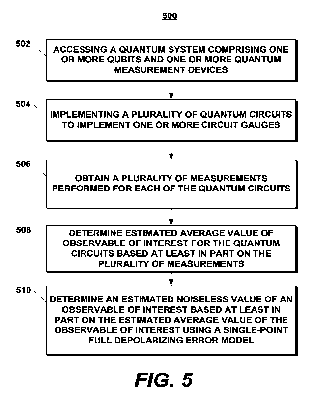
[0073] FIG. 5 depicts a flow diagram of an example
method 500 according to example
aspects of the present disclosure. The method 500 can be implemented using any
suitable
quantum computing system, such as the quantum computing system 100 depicted in
FIG. 1_
FIG. 5 depicts steps performed in a particular order for purposes of
illustration and
discussion. Those of ordinary skill in the art, using the disclosures provided
herein, will
understand that various steps of any of the methods disclosed herein can be
adapted,
modified, performed simultaneously, omitted, include steps not illustrated,
rearranged, and/or
expanded in various ways without deviating from the scope of the present
disclosure.
[0074] At 502, the method 500 can include accessing a
quantum system (e.g., the
quantum system 110 and/or the quantum hardware 102 of FIG. 1). The quantum
system can
include one or more quantum system qubits and one or more quantum measurement
devices.
The quantum system can be configured to implement a plurality of quantum
circuits. Each of
14
CA 03158890 2022-5-18
WO 2021/101829
PCT/US2020/060685
the plurality of quantum circuits can be implemented by a different sequence
of quantum
gates as compared to each of the other quantum circuits in the plurality to
thereby implement
one or more circuit gauges.
[0075] At 504, the method 500 can include implementing
a plurality of quantum circuits.
The plurality of quantum circuits can each be implemented by a different
sequence of
quantum gates as compared to each of the other quantum circuits in the
plurality to
implement one or more circuit gauges. In some implementations, the one or more
circuit
gauges can be one or more randomized circuit gauges. For example, one or more
pairs of
Pauli operators can be propagated through a quantum circuit. In some
implementations, the
one or more quantum circuits can include (e.g., incorporate) one or more
Clifford gates. In
some implementations, the one or more quantum circuits can include (e.g.,
incorporate) one
or more non-Clifford gates.
[0076] At 506, the method 500 can include obtaining a
plurality of measurements
performed for the one or more quantum circuits. For example, quantum
measurement
device(s) (e.g., readout resonator(s)) can obtain one or more measurements for
each of the
one or more quantum circuits.
[0077] At 508, the method 500 can include determining
an estimated average value of an
observable of interest (0)f for the quantum circuits based at least in part on
the plurality of
measurements.
[0078] At 510, the method 500 can include determining
an estimated noiseless value of
an observable of interest (0)0 based at least in part on the estimated average
value of the
observable of interest (0)1- using a single-point full depolarizing error
model.
[0079] For example, in some implementations,
determining the estimated noiseless value
of the observable of interest (0)0 based at least in part on the estimated
average value of the
observable of interest (0)1using the single-point full depolarizing error
model can include
determining an approximation of a circuit fidelity f for the one or more
circuit gauges. In
some implementations, the approximation of the circuit fidelity f for the one
or more circuit
gauges can include a component cross entropy benchmarking for a similar
circuit structure. In
some implementations, the approximation of the circuit fidelity f for the one
or more circuit
gauges can include counting a number of single and two qubit gates in a
circuit and using a
circuit fidelity for those types of gates.
[0080] In some implementations, determining the
estimated noiseless value of the
observable of interest (0)* based at least in part on the estimated average
value of the
CA 03158890 2022-5-18
WO 2021/101829
PCT/US2020/060685
observable of interest (0) f using the single-point full depolarizing error
model can further
include determining the inferred average value of the observable (0)4, based
at least in part
on the average value of the observable of interest (0) f and the approximation
of the circuit
fidelity f.
[0081] For example, in some implementations,
determining the inferred average value of
the observable of interest (0)* based at least in part on the average value of
the observable of
interest (0)f. and the approximation of the circuit fidelity f can include
determining the
inferred average value of the observable (0)0 according to the formula (0) f =
f(0)g, +
¨(1-f) Tr[0], where 0 is a desired observable and ¨(1-f) Tr [0] comprises a
component
2n 2n
attributable to noise.
[0082] Determining the estimated noiseless value of
the observable of interest (0)*
based at least in part on the estimated average value of the observable of
interest (0)f using
the single point full depolarizing error model can include determining an
error corrected
observable of interest 0 by correcting for a noise component of the plurality
of
measurements.
[0083] FIG. 6 depicts a flow diagram of an example
method 600 according to example
aspects of the present disclosure. The method 600 can be implemented using any
suitable
quantum computing system, such as the quantum computing system 100 depicted in
FIG. 1.
FIG. 6 depicts steps performed in a particular order for purposes of
illustration and
discussion. Those of ordinary skill in the art, using the disclosures provided
herein, will
understand that various steps of any of the methods disclosed herein can be
adapted,
modified, performed simultaneously, omitted, include steps not illustrated,
rearranged, and/or
expanded in various ways without deviating from the scope of the present
disclosure.
[0084] At 602, the method 600 can include accessing a
quantum system (e.g., the
quantum system 110 and/or the quantum hardware 102 of FIG. 1). The quantum
system can
include one or more quantum system qubits and one or more quantum measurement
devices.
The quantum system can be configured to implement a plurality of quantum
circuits. Each of
the plurality of quantum circuits can be implemented by a different sequence
of quantum
gates as compared to each of the other quantum circuits in the plurality to
thereby implement
one or more circuit gauges.
[0085] At 604, the method 600 can include implementing
a plurality of quantum circuits.
The plurality of quantum circuits can each be implemented by a different
sequence of
16
CA 03158890 2022-5-18
WO 2021/101829
PCT/US2020/060685
quantum gates as compared to each of the other quantum circuits in the
plurality to
implement one or more circuit gauges. In some implementations, the one or more
circuit
gauges can be one or more randomized circuit gauges. For example, one or more
pairs of
Pauli operators can be propagated through a quantum circuit. In some
implementations, the
one or more quantum circuits can include (e.g., incorporate) one or more
Clifford gates. In
some implementations, the one or more quantum circuits can include (e.g.,
incorporate) one
or more non-Clifford gates. In some implementations, the one or more quantum
circuits can
include one or more quantum circuits configured to implement a preferred error
direction for
error mitigation.
100861 At 606, the method 600 can include obtaining a
plurality of measurements
performed for the one or more quantum circuits. For example, quantum
measurement
device(s) (e.g., readout resonator(s)) can obtain one or more measurements for
each of the
one or more quantum circuits.
100871 At 608, the method 600 can include determining
an estimated average value of an
observable of interest (0)! for the quantum circuits based at least in part on
the plurality of
measurements.
100881 At 610, the method 600 can include implementing
an error mitigation scheme for
the quantum system based at least in part on the average value of the
observable of interest
(0)g. In some implementations, a single-point full depolarizing error
mitigation scheme can
be used. In some implementations, a multi-point extrapolation scheme can be
used. In some
implementations, an error correction code can be used.
100891 Implementations of the digital and/or quantum
subject matter and the digital
functional operations and quantum operations described in this specification
can be
implemented in digital electronic circuitry, suitable quantum circuitry or,
more generally,
quantum computational systems, in tangibly-implemented digital and/or quantum
computer
software or firmware, in digital and/or quantum computer hardware, including
the structures
disclosed in this specification and their structural equivalents, or in
combinations of one or
more of them. The term "quantum computing systems" may include, but is not
limited to,
quantum computers/computing systems, quantum information processing systems,
quantum
cryptography systems, or quantum simulators.
100901 Implementations of the digital and/or quantum
subject matter described in this
specification can be implemented as one or more digital and/or quantum
computer programs,
i.e., one or more modules of digital and/or quantum computer program
instructions encoded
17
CA 03158890 2022-5-18
WO 2021/101829
PCT/US2020/060685
on a tangible non-transitory storage medium for execution by, or to control
the operation of,
data processing apparatus. The digital and/or quantum computer storage medium
can be a
machine-readable storage device, a machine-readable storage substrate, a
random or serial
access memory device, one or more qubits/qubit structures, or a combination of
one or more
of them. Alternatively or in addition, the program instructions can be encoded
on an
artificially-generated propagated signal that is capable of encoding digital
and/or quantum
information (e.g., a machine-generated electrical, optical, or electromagnetic
signal) that is
generated to encode digital and/or quantum information for transmission to
suitable receiver
apparatus for execution by a data processing apparatus.
100911 The terms quantum information and quantum data
refer to information or data
that is carried by, held, or stored in quantum systems, where the smallest non-
trivial system is
a qubit, i.e., a system that defines the unit of quantum information. It is
understood that the
term "qubit" encompasses all quantum systems that may be suitably approximated
as a two-
level system in the corresponding context. Such quantum systems may include
multi-level
systems, e.g., with two or more levels. By way of example, such systems can
include atoms,
electrons, photons, ions or superconducting qubits. In many implementations
the
computational basis states are identified with the ground and first excited
states, however it is
understood that other setups where the computational states are identified
with higher level
excited states (e.g., qudits) are possible.
100921 The term "data processing apparatus" refers to
digital and/or quantum data
processing hardware and encompasses all kinds of apparatus, devices, and
machines for
processing digital and/or quantum data, including by way of example a
programmable digital
processor, a programmable quantum processor, a digital computer, a quantum
computer, or
multiple digital and quantum processors or computers, and combinations thereof
The
apparatus can also be, or further include, special purpose logic circuitry,
e.g., an FPGA (field
programmable gate array), or an ASIC (application-specific integrated
circuit), or a quantum
simulator, i.e., a quantum data processing apparatus that is designed to
simulate or produce
information about a specific quantum system. In particular, a quantum
simulator is a special
purpose quantum computer that does not have the capability to perform
universal quantum
computation. The apparatus can optionally include, in addition to hardware,
code that creates
an execution environment for digital and/or quantum computer programs, e.g.,
code that
constitutes processor firmware, a protocol stack, a database management
system, an operating
system, or a combination of one or more of them.
18
CA 03158890 2022-5-18
WO 2021/101829
PCT/US2020/060685
[0093] A digital computer program, which may also be
referred to or described as a
program, software, a software application, a module, a software module, a
script, or code, can
be written in any form of programming language, including compiled or
interpreted
languages, or declarative or procedural languages, and it can be deployed in
any form,
including as a stand-alone program or as a module, component, subroutine, or
other unit
suitable for use in a digital computing environment. A quantum computer
program, which
may also be referred to or described as a program, software, a software
application, a module,
a software module, a script, or code, can be written in any form of
programming language,
including compiled or interpreted languages, or declarative or procedural
languages, and
translated into a suitable quantum programming language, or can be written in
a quantum
programming language, e.g., QCL, Quipper, Cirq, etc..
[0094] A digital and/or quantum computer program may,
but need not, correspond to a
file in a file system. A program can be stored in a portion of a file that
holds other programs
or data, e.g., one or more scripts stored in a markup language document, in a
single file
dedicated to the program in question, or in multiple coordinated files, e.g.,
files that store one
or more modules, sub-programs, or portions of code. A digital and/or quantum
computer
program can be deployed to be executed on one digital or one quantum computer
or on
multiple digital and/or quantum computers that are located at one site or
distributed across
multiple sites and interconnected by a digital and/or quantum data
communication network.
A quantum data communication network is understood to be a network that may
transmit
quantum data using quantum systems, e.g. qubits. Generally, a digital data
communication
network cannot transmit quantum data, however a quantum data communication
network
may transmit both quantum data and digital data
[0095] The processes and logic flows described in this
specification can be performed by
one or more programmable digital and/or quantum computers, operating with one
or more
digital and/or quantum processors, as appropriate, executing one or more
digital and/or
quantum computer programs to perform functions by operating on input digital
and quantum
data and generating output. The processes and logic flows can also be
performed by, and
apparatus can also be implemented as, special purpose logic circuitry, e.g.,
an FPGA or an
ASIC, or a quantum simulator, or by a combination of special purpose logic
circuitry or
quantum simulators and one or more programmed digital and/or quantum
computers.
[0096] For a system of one or more digital ancUor
quantum computers or processors to
be "configured to" or "operable to" perform particular operations or actions
means that the
system has installed on it software, firmware, hardware, or a combination of
them that in
19
CA 03158890 2022-5-18
WO 2021/101829
PCT/US2020/060685
operation cause the system to perform the operations or actions. For one or
more digital
and/or quantum computer programs to be configured to perform particular
operations or
actions means that the one or more programs include instructions that, when
executed by
digital and/or quantum data processing apparatus, cause the apparatus to
perform the
operations or actions. A quantum computer may receive instructions from a
digital computer
that, when executed by the quantum computing apparatus, cause the apparatus to
perform the
operations or actions.
[0097] Digital and/or quantum computers suitable for
the execution of a digital and/or
quantum computer program can be based on general or special purpose digital
and/or
quantum microprocessors or both, or any other kind of central digital and/or
quantum
processing unit. Generally, a central digital and/or quantum processing unit
will receive
instructions and digital and/or quantum data from a read-only memory, or a
random access
memory, or quantum systems suitable for transmitting quantum data, e.g.
photons, or
combinations thereof
[0098] Some example elements of a digital and/or
quantum computer are a central
processing unit for performing or executing instructions and one or more
memory devices for
storing instructions and digital and/or quantum data. The central processing
unit and the
memory can be supplemented by, or incorporated in, special purpose logic
circuitry or
quantum simulators. Generally, a digital and/or quantum computer will also
include, or be
operatively coupled to receive digital and/or quantum data from or transfer
digital and/or
quantum data to, or both, one or more mass storage devices for storing digital
and/or quantum
data, e.g., magnetic, magneto-optical disks, or optical disks, or quantum
systems suitable for
storing quantum information. However, a digital and/or quantum computer need
not have
such devices.
[0099] Digital and/or quantum computer-readable media
suitable for storing digital
and/or quantum computer program instructions and digital and/or quantum data
include all
forms of non-volatile digital and/or quantum memory, media and memory devices,
including
by way of example semiconductor memory devices, e.g., EPROM, EEPROM, and flash
memory devices; magnetic disks, e.g., internal hard disks or removable disks;
magneto-
optical disks; and CD-ROM and DVD-ROM disks; and quantum systems, e.g.,
trapped atoms
or electrons. It is understood that quantum memories are devices that can
store quantum data
for a long time with high fidelity and efficiency, e.g., light-matter
interfaces where light is
used for transmission and matter for storing and preserving the quantum
features of quantum
data such as superposition or quantum coherence.
CA 03158890 2022-5-18
WO 2021/101829
PCT/US2020/060685
[0100] Control of the various systems described in
this specification, or portions of
them, can be implemented in a digital and/or quantum computer program product
that
includes instructions that are stored on one or more non-transitory machine-
readable storage
media, and that are executable on one or more digital and/or quantum
processing devices.
The systems described in this specification, or portions of them, can each be
implemented as
an apparatus, method, or electronic system that may include one or more
digital and/or
quantum processing devices and memory to store executable instructions to
perform the
operations described in this specification.
[0101] While this specification contains many specific
implementation details, these
should not be construed as limitations on the scope of what may be claimed,
but rather as
descriptions of features that may be specific to particular implementations.
Certain features
that are described in this specification in the context of separate
implementations can also be
implemented in combination in a single implementation. Conversely, various
features that are
described in the context of a single implementation can also be implemented in
multiple
implementations separately or in any suitable sub combination. Moreover,
although features
may be described above as acting in certain combinations and even initially
claimed as such,
one or more features from a claimed combination can in some cases be excised
from the
combination, and the claimed combination may be directed to a sub-combination
or variation
of a sub-combination.
[0102] Similarly, while operations are depicted in the
drawings in a particular order, this
should not be understood as requiring that such operations be performed in the
particular
order shown or in sequential order, or that all illustrated operations be
performed, to achieve
desirable results. In certain circumstances, multitasking and parallel
processing may be
advantageous. Moreover, the separation of various system modules and
components in the
implementations described above should not be understood as requiring such
separation in all
implementations, and it should be understood that the described program
components and
systems can generally be integrated together in a single software product or
packaged into
multiple software products.
[0103] Particular implementations of the subject
matter have been described. Other
implementations are within the scope of the following claims. For example, the
actions
recited in the claims can be performed in a different order and still achieve
desirable results.
As one example, the processes depicted in the accompanying figures do not
necessarily
require the particular order shown, or sequential order, to achieve desirable
results. In some
cases, multitasking and parallel processing may be advantageous.
21
CA 03158890 2022-5-18