Note: Descriptions are shown in the official language in which they were submitted.
TRANSPORT TRAY FOR PACKAGING UNITS
[0001] This disclosure relates to a tray for transporting packaging
units.
[0002] In industrial contexts, products are generally transported
and sold in
packaging units. Packaging units can include vials, call" _____________ idges,
ampoules, bottles, or pre-
fillable syringes. In many industries, these different types of packaging
units are
collectively known as "primary packaging," i.e., the packaging that comes into
direct
contact with an end product. The end product may be a food product, a cosmetic
product,
or a pharmaceutical product. Primary packaging can undergo numerous
manufacturing
processes before being filled with the end product. During these processes,
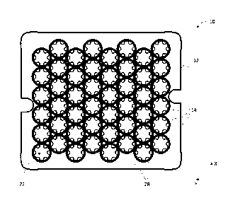
primary
packaging is often transported and processed in batches.
[0003] US 10,703,539 B2 describes a carrier in which retaining
protrusions provided at lower ends of apertures or receptacles of a supporting
structure
protrude inward in a radial direction into the apertures or receptacles for
supporting vials
in cooperation with transition regions or edge portions of the vials in such a
manner that
bottoms of the vials, or more generally the lower ends of the vials, jut out
of the apertures
or receptacles and are thus are freely accessible from the lower side of the
carrier.
[0004] US 2018/0208377 Al describes a supporting structure that has
an upper
side or base plane, which generally is formed as a plate and whose
circumferential edge
is formed flat. In the upper side, a plurality of openings is formed, which
are arranged
in rows and columns extending perpendicular to each other. The openings of
adjacent
rows or columns are arranged staggered relative to each other, which enables a
higher
packing density with the hexagonal arrangement of the peripheral webs. A
plurality of
axial connecting webs protrude perpendicularly from the underside of the
supporting
structure, which are connected to each other at their lower ends via
circumferential
bottom webs.
[0005] WO 2014/130349 Al describes a tray with receptacles that are
configured to support vials in different manners during different stages of
processing.
Each receptacle has a bottom opening defined at a bottom edge of lower portion
of a
cylindrical wall, and an inwardly extending lip surrounding each opening. The
opening
1
Date Recue/Date Received 2022-05-17
has an inner diameter slightly smaller than the outer diameter of the vial
side wall, but
slightly larger than the bottom wall, such that the inner edges of lip contact
a portion of
curved lower edge joining side wall and bottom wall. This configuration
permits the vial
to be supported by the tray while suspended, with a lower portion of the vial
protruding
downward from the bottom edge of the tray.
[0006] Aspects of the present disclosure aim to alleviate problems
associated
with known transport trays.
[0007] According to a general aspect of the present disclosure, a
transport tray
includes a plurality of sleeves that are each configured to receive a
substantially
to cylindrical container having a cylindrical container wall and a
container bottom surface
arranged orthogonally to the container wall. Each sleeve includes a top
opening, a
bottom opening, a sleeve wall that extends along a sleeve axis between the top
opening
and the bottom opening and is configured to abut at least a portion of the
container wall
of a respective container, and one or more support feet that are adjacent to
the bottom
opening and extend from the sleeve wall towards the sleeve axis, wherein each
support
foot comprises a bottom surface and a top surface configured to abut the
container
bottom surface of a respective container, such that a gap is formed between
the support
foot bottom surface and the container bottom surface along the sleeve axis.
The one or
more support feet comprise a thermally conductive polymer.
[0008] In some instances, each sleeve can include a ring that connects the
one
or more support feet to the bottom opening and that comprises a thermally
conductive
polymer. Further, each sleeve can be a monolithic structure that comprises a
thermally
conductive polymer.
[0009] In addition to the respective sleeves, the entire transport
tray may be a
monolithic structure that comprises a thermally conductive polymer. For
example, the
transport tray may be manufactured by injection molding a thermally conductive
polymer.
[0010] The thermally conductive polymer may comprise an aluminum
filler, a
zinc filler, or a combination thereof.
2
Date Recue/Date Received 2022-05-17
[0011] Each sleeve wall may include a closed cylinder that encircles
the sleeve
axis.
[0012] The top opening of each sleeve may be larger than the bottom
opening,
such that the sleeve wall forms an angle greater than 00 relative to the
sleeve axis.
[0013] The transport tray may include a plate portion connected to the top
opening of each sleeve. A connecting portion may connect the sleeve walls of
at least
two adjacent sleeves to the plate portion. The plate portion may comprise a
plurality of
corner regions and a raised bumper arranged at each corner region. Such a
raised bumper
has a height that is greater than a thickness of the plate portion. Each
raised bumper may
include at least one projection that extends outward from a perimeter of the
plate portion.
The perimeter of the plate portion may include the raised bumpers and an edge
portion
having the same thickness as the plate portion arranged between each pair of
adjacent
raised bumpers.
[0014] These and other embodiments described herein may provide one
or more
of the following benefits. The transport tray may be suitable for transferring
heat to and
from the packaging units. For example, the transport tray may be used in a
lyophilization
process. At the same time, the transport tray may securely support the
packaging units
in other processes, such as direct filling processes. Overall, the transport
tray may reduce
the need to handle individual packaging units during the manufacturing
process. Further,
the design of the transport tray may be compatible with existing equipment.
The
transport tray may also prove to be robust.
[0015] Certain embodiments will now be described, by way of example
only,
with reference to the accompanying drawings, in which:
Figure 1 shows a transport tray according to the present disclosure from
above;
Figure 2 shows a perspective view of the transport tray of Figure 1;
Figure 3 shows a partial perspective view of a bottom of the transport tray of
Figure 1;
Figures 4A and 4B show cross-sectional views through the transport tray of
Figures 1
to 3;
Figures 5A and 5B schematically show multiple transport trays placed next to
one
another on a table; and
Figure 5C shows a partial perspective view of the transport tray of Figure 2.
3
Date Recue/Date Received 2022-05-17
[0016] Like
reference numbers and designations in the various drawings indicate
like elements.
[0017] Figure
1 shows a transport tray 10 according to the present disclosure
from above. The transport tray 10 includes a plate portion 12 and a plurality
of sleeves
14. The sleeves 14 are each configured to receive a substantially cylindrical
container
16 having a cylindrical container wall 18 and a container bottom surface 20
arranged
orthogonally to the container wall 18 (Figure 4A). The containers 16 can serve
as
primary packaging for various types of end products. Although the expression
"primary
packaging" can encompass vials, cal ___________________________________
nidges, ampoules, bottles, and syringes to name a
ul few examples, the figures of the present disclosure illustrate vials.
The transport tray 10
can be used to group and transport the vials 16 throughout different
manufacturing
processes, for example.
[0018] As
shown in Figure 2, each sleeve 14 includes a top opening 22, a bottom
opening 24, a sleeve wall 26 that extends along a sleeve axis between the top
opening
22 and the bottom opening 24. Referring to the coordinate axes shown in Figure
2, the
sleeve axis of each sleeve 14 extends along the Z-axis.
[0019]
Figures 3 and 4 show the transport tray 10 of Figures 1 and 2 with a
plurality of containers 16 arranged in the sleeves 14. The containers 16 are
arranged in
the sleeves 14 such that the sleeve wall 26 faces the container wall 18
(Figure 4A). The
container 16 includes an opening 17 that is arranged facing the top opening 22
of the
sleeve 14, while the bottom surface 20 of the container is adjacent to the
bottom opening
24 of the sleeve 14. Each sleeve 14 includes one or more support feet 28 that
are adjacent
to the bottom opening 24 and extend from the sleeve wall 26 towards the sleeve
axis.
Each support foot 28 comprises a bottom surface 28a and a top surface 28b
configured
to abut the container bottom surface 20 of the container 16 received in the
sleeve. The
support foot 28 is designed so that a gap G is formed between the support foot
bottom
surface 28a and the container bottom surface 20 along the sleeve axis (Figure
4B).
[0020]
Accordingly, the transport tray 10 rests on the collective support foot
bottom surfaces 28a of each of the support feet 28, while each container
bottom surface
20 rests entirely on the support foot top surfaces 28b of the support feet 28
in a respective
sleeve 14. As shown in Figures 4A and 4B, the container bottom surface 20 does
not
4
Date Recue/Date Received 2022-05-17
extend past the support feet 28. In other words, the container bottom surface
20 is
separated from the surface on which the transport tray 10 rests. In practice,
this may
mean that the support foot top surface 28b makes contact with the lowest point
of the
container bottom surface 20.
[0021] According to the present disclosure, the one or more support feet 28
include a thermally conductive polymer. For example, the one or more support
feet 28
are formed as a single part, e.g., of injection molded plastic with thermally
conductive
fillers. Such support feet 28 may be attached to the sleeves 14 using insert
molding
techniques. For example, the filler may include an aluminum filler, a zinc
filler, or a
113 combination thereof. In some instances, the one or more support feet 28
can be attached
to the bottom opening 24 by a ring 29 (Figure 3). The ring 29 may also include
a
thermally conductive polymer. The ring 29 and the one or more support feet 28
may be
integrally formed, i.e., form a monolithic structure. In some instances, the
entire sleeve
14, or even the entire support tray 10, may be a monolithic structure. For
example, the
transport tray 10 may be manufactured by injection molding a thermally
conductive
polymer. As described above, the container bottom surface 20 rests on the
support foot
top surfaces 28b of each sleeve 14.
[0022] Since at least the one or more support feet 28 include
thermally
conductive polymer, the support feet 28 are able to transfer heat to and from
the
container bottom surface 20. Accordingly, the transport tray 10 may be used
during a
lyophilization process with the containers 16 remaining in the sleeves 14.
Since the
container bottom surface 20 does not protrude through the bottom opening 24 of
the
sleeve 14, the same transport tray 10 can be used for other processes, e.g., a
direct fill
process. Thus, the transport tray 10 according to the present disclosure may
contribute
to the efficiency of the manufacturing process for primary packaging.
[0023] The transport tray 10 may include any number of the following
features
that may improve the robustness and heat transfer of the transport tray 10.
[0024] As shown in Figure 3, for example, each sleeve wall 26 may
include a
closed cylinder that completely encircles the sleeve axis and, thus, a portion
of the
container wall 18. In cases in which the entire sleeve 14 includes a thermally
conductive
polymer, this closed cylinder design can increase the amount of thermally
conductive
5
Date Recue/Date Received 2022-05-17
polymer that surrounds the container wall 18 and improve heat transfer, e.g.,
during the
lyophilization process. At the same time, the closed cylinder may improve the
robustness
of the sleeve 14 and transport tray 10, respectively.
[0025] The top opening 22 of each sleeve 14 may be larger than the
bottom
opening 24, such that the sleeve wall forms an angle greater than 00 relative
to the sleeve
axis. Such a taper may make it easier to retrieve the container 16 from the
sleeve 14
despite the closed cylinder design described above.
[0026] As shown in Figure 4A, the transport tray 10 may include a
connecting
portion 30 that connects the sleeve walls 26 of at least two adjacent sleeves
to the plate
portion 12. The connecting portion 30 can also increase the volume of
thermally
conductive polymer and, thus, the heat transfer through the transport tray 10
and its
overall robustness.
[0027] Figures 5A to 5C show optional features of the transport tray
10 that may
enable several transport trays 10 to be neatly stacked next to one another. As
shown in
Figure 5A, a first and second transport tray 10 are each loaded with a
plurality of
containers 16 and placed next to one another on a table 32. For example, the
table 32
may be used for a lyophilization process to rapidly cool the containers 16 and
their
contents.
[0028] As shown in the enlarged portion of Figure 5A, the plate
portions 12 of
each transport tray 10 are arranged closely next to each other without
touching. Such an
arrangement may allow the greatest possible number of containers 16 to be
placed on
the table at once. Figure 5B shows a scenario in which adjacent transport
trays 10 have
been placed so closely together that the plate portions 12 overlap. This
overlap in the
plate portions creates a gap 34 between the table 32 and the transport tray 10
on the
right. This gap 34 may reduce the efficiency of the heat transfer between the
table 32,
the transport tray 10, and the containers 16.
[0029] In order to prevent the overlap shown in Figure 5B, each
corner region
36 of the plate portion 12 may be provided with one or more features that
reduce the
likelihood that adjacent transport trays 10 overlap one another. As shown in
Figure 5C,
each comer region 36 of the plate portion 12 can include a raised bumper 38.
In the
6
Date Recue/Date Received 2022-05-17
context of this disclosure, "raised" can mean that a height of the bumper 38
along the Z-
axis is greater than a thickness of the plate portion 12 along the Z-axis.
When two
transport trays 10 are brought close together, the matching bumpers 38 may
come into
contact and prevent the plate portions 12 from overlapping.
[0030] In some instances, the raised bumper 38 can include a first and a
second
projection 40 that increase the stability of the raised bumper 38. In Figure
5C, the first
projection 40 extends outward from the plate portion 12 along the X-axis, and
the second
projection 40 extends outward from the plate portion 12 along the Y-axis.
[0031] The raised bumper 38 can include a strip of material that
continuously
wraps around the corner region 36 of the plate portion. Each end of the raised
bumper
38 can abut an edge portion 42 of the plate portion 12 that does not have an
increased
thickness (see also Figure 2). In some instances, the combination of
alternating raised
bumpers 38 and edge portions 42 may improve air flow during injection molding
of the
transport tray 10. However, it is also possible for the raised bumper 38 to
extend around
the entire perimeter of the plate portion 12.
[0032] A number of embodiments have been described. Nevertheless,
numerous
alternative embodiments within the scope of the claims will be readily
appreciated by
those skilled in the art. The presently described embodiments are not to be
taken as
limiting the scope of the invention.
7
Date Recue/Date Received 2022-05-17