Note: Descriptions are shown in the official language in which they were submitted.
PROCESSING METHOD FOR PACKAGING UNITS
[0001] This
disclosure relates to a method of processing packaging units and a
combination that includes a container and a plurality of packaging units.
[0002] In
industrial contexts, products are generally transported and sold in
packaging units. Packaging units can include vials, cal ______ Li idges,
ampoules, bottles, or pre-
fillable syringes. In many industries, these different types of packaging
units are
collectively known as "primary packaging," i.e., the packaging that comes into
direct
contact with an end product. The end product may be a food product, a cosmetic
product,
or a pharmaceutical product, for example. Primary packaging can undergo
numerous
manufacturing processes before being filled with the end product. During these
processes, primary packaging is often processed in batches.
[0003] The
present disclosure aims to provide a method for processing
packaging units made of glass.
[0004]
According to a first general aspect of the present disclosure, a method
includes receiving a plurality of packaging units made of glass, coating at
least a portion
of an outer surface of each packaging unit with low-friction coating, curing
the low-
friction coating applied to the outer surface of each packaging unit,
receiving a container
configured to store the plurality of packaging units, and arranging each
packaging unit
in the container with the outer surface of each packaging unit able to touch
the outer
surface of one or more adjacent packaging units.
[0005] The
packaging units may be vials, ampoules, cathidges, or syringe
bodies and, thus, primary packaging in the food, cosmetic, or pharmaceutical
industries,
for example.
[0006] The
low-friction coating may include fluoropolymer coating. For
example, the low-friction coating may include perfluoroalkoxy alkane (PFA)
coating.
[0007]
Coating at least a portion of an outer surface of each packaging unit with
low-friction coating may include sealing an opening of the packaging unit, and
rotating
the packaging unit as the low-friction coating is sprayed onto at least a
portion of an
1
Date Recue/Date Received 2022-05-17
outer surface of the packaging unit. Optionally, a pressure differential may
be created to
attract the sprayed coating to the outer surface of the packaging unit.
Alternatively,
coating at least a portion of an outer surface of each packaging unit with low-
friction
coating may include submersing the outer surface of each packaging unit in the
low-
s friction coating. For example, the packaging units may be submerged to a
certain point
(e.g., the neck of a vial) to prevent the low-friction coating from entering
the packaging
unit through the opening.
[0008] Once the plurality of packaging units is arranged in the
container, the
container may be closed for further transport. For example, the container may
be sealed
with a flexible film lid or closed with a rigid or semi-rigid lid. In some
instances, the
closed container may be arranged in a sterile bag that is permeable to vapors
but not to
liquid, for example.
[0009] The plurality of packaging units may be sterilized. For
example, the
method may include sterilizing the plurality of packaging units before or
after the
packaging units have been arranged in the container.
[0010] According to a second general aspect of the present
disclosure, a
combination includes a container, and a plurality of packaging units arranged
in the
container such that an outer surface of each packaging unit is able to touch
the outer
surface of one or more adjacent packaging units, wherein the packaging units
are made
of glass, and the outer surface of each packaging unit comprises a low-
friction coating.
[0011] The low-friction coating may include fluoropolymer coating,
in
particular, perfluoroalkoxy alkane (PFA) coating.
[0012] The combination may further include a flexible lid that seals
the
container or a rigid or semi-rigid lid that closes the container.
[0013] These and other embodiments described herein may provide one or more
of the following benefits. The low-friction coating may suppress mechanical
damage to
packaging units and provide a more robust packaging unit. Increased robustness
may
reduce the number of rejected units and increase handling speed across various
2
Date Recue/Date Received 2022-05-17
manufacturing processes. The batches of packaging units may be densely packed
in
transport containers, further improving the efficiency of downstream
processes.
[0014] Certain embodiments will now be described, by way of example
only,
with reference to the accompanying drawings, in which:
Figure 1 shows a schematic overview of a method according to the present
disclosure;
Figure 2 is a schematic side view of a vial that can be used in the method
according to
the present disclosure;
Figures 3A and 3B each show a schematic overview of an arrangement for coating
the
outer surface of a packaging unit;
Figure 4 is a schematic top view of a combination of a container and plurality
of
packaging units according to the present disclosure; and
Figure 5 shows a schematic cross-sectional view of a further combination
according to
the present disclosure.
[0015] Like reference numbers and designations in the various
drawings indicate
like elements.
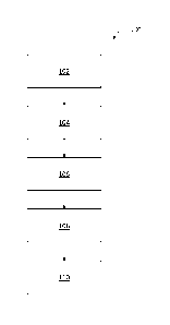
[0016] Figure 1 shows a schematic overview of a method 100 according
to the
present disclosure. The method 100 includes receiving 102 a plurality of
packaging units
made of glass, coating 104 at least a portion of an outer surface of each
packaging unit
with low-friction coating, curing 106 the low-friction coating applied to the
outer surface
of each packaging unit, receiving 108 a container configured to store the
plurality of
packaging units, and arranging 110 each packaging unit in the container with
the outer
surface of each packaging unit able to touch the outer surface of one or more
adjacent
packaging units.
[0017] In the following description, vials are described as an
example of
packaging units. Vials can be used to store pre-portioned amounts of a liquid
or non-
liquid end product and often serve as primary packaging, e.g., in the
pharmaceutical
industry. However, the method 100 is not restricted to vials. Other types of
packaging
units can include ampoules, cal tlidges, or syringe bodies to name a few
examples.
[0018] Figure 2 is a schematic side view of a vial 10. The vial 10
includes a
substantially cylindrical body 12 made of glass that includes an opening 14, a
bottom
3
Date Recue/Date Received 2022-05-17
surface 16, and an outer surface 18. The body 12 defines an inner space 20
that can be
filled with a liquid or non-liquid product. The inner space 20 is communicated
with the
opening 14. The body 12 comprises a large diameter section 22, a neck section
24 that
connects to the large diameter section 22, and an optional opening rim 26. A
shoulder
or transition region 28 is formed between the large diameter section 22 and
the neck
section 24. Although Figure 2 shows the body 12 with sharp comers, the body 12
may
include curved surfaces, particularly in the neck section 24, the transition
region 28, and
the bottom surface 16.
[0019] As described in reference to Figure 1, the method 100 can
include
receiving a plurality of the vials 10 shown in Figure 2. For example, the vial
10 can be
manufactured by forming and annealing a glass material, such as borosilicate
glass.
[0020] The method 100 can further include coating at least a portion
of the vial's
outer surface 18 with low-friction coating. In some instances, the entire
outer surface 18
of the vial body 12 can be coated. However, the low-friction coating can also
be limited
to a portion of the outer surface 18 that corresponds to the large diameter
section 22, for
example. This part of the outer surface 18 is likely to come into contact with
other vials
(so-called glass-on-glass contact) that can lead to mechanical damage, such as
scratches
and abrasions. The transition region 28, the neck section 24, and the optional
opening
rim 26 may remain uncoated to prevent the coating from entering the inner
space 20 via
the opening 14.
[0021] Figure 3A shows a schematic overview of an arrangement for
coating at
least a portion of the vial's outer surface 18 with low-friction coating. The
opening 14
of the vial 10 may be sealed, as schematically shown by a stopper 30. The vial
10 may
be rotated as a spray gun 32 directs a spray 34 of low-friction coating
towards the outer
surface 18 of the vial 10. In some instances, a pressure differential P (e.g.,
a vacuum)
may be created on the opposite side of the vial 10 to the spray gun 32 to
attract the spray
34 towards the outer surface 18 of the vial 10. As illustrated, the spray 34
is directed to
the large diameter section 22 (Figure 2) of the vial 10. In some instances,
the spray 34
may cover additional parts of the vial 10, such as the neck section 24.
[0022] Figure 3B shows a schematic overview of a further arrangement for
coating at least a portion of the vial's outer surface 18 with low-friction
coating.
4
Date Recue/Date Received 2022-05-17
Specifically, the vial 10 can be submersed in a bath 36 of low-friction
coating, as
indicated by the arrow 38. The vial 10 may be submersed so that certain
portions of the
body remain exposed and free from coating, e.g., the transition region 28, the
neck
section 24, and the opening rim 26.
[0023] Although Figures 3A and 3B each show an individual vial 10, the
arrangements can be used to coat multiple vials 10 at once. Further, although
the
arrangements may be used with various types of low-friction coating, the spray
34 and
the bath 36 may include fluoropolymer coating in some examples. More
specifically,
the spray 34 and the bath 36 may include perfluoroalkoxy alkane (PFA) coating.
113 [0024] Following the coating, the vials 10 are cured to allow
the low-friction
coating to adhere to the outer surface 18. The curing process may evaporate or
volatize
processing aids that are incorporated into the spray 34 or the bath 36. In
some instances,
the vials 10 may be washed after curing to remove any remaining particles of
the low-
friction coating that have not adhered to the vial 10. In this way, a low-
friction and
scratch-resistant coating is formed on the vials 10. The reduced coefficient
of friction
may suppress mechanical damage to the vials 10. The reduced likelihood of
damage can
also increase the speed and efficiency of handling in subsequent processes, as
described
below in more detail.
[0025] Figure 4 is a schematic top view of a container 40 with a
plurality of vials
10 arranged inside. Before being placed in the container 40, the vials 10 have
been
provided with a low-friction coating as previously described. As shown in
Figure 4, the
vials 10 are arranged in a plurality of rows such that an outer surface of
each vial 10 is
able to touch the outer surface of one or more adjacent vials 10. In this
instance, "able
to touch" can mean that the vials 10 are placed adjacent to one another
without an
intermediate support structure between the vials 10. The low-friction coating
enables the
vials 10 to be packaged independently of an intermediate support structure
(commonly
referred to as a "nest"). Accordingly, the vials 10 can be packed with higher
density than
may otherwise be the case. Further, the vials 10 can be packed in different
arrangements
of rows in the same container 40.
[0026] In addition to allowing tight packing of the vials 10 inside of the
container 40, the low-friction coating may provide a more homogenous thermal
5
Date Recue/Date Received 2022-05-17
distribution across the glass surface of the vial 10. This homogenous thermal
distribution
may be useful during a lyophilization procedure.
[0027] After the vials 10 have been arranged in the container 40,
the container
40 may be closed for further transport and processing of the vials 10. Figure
5 shows a
schematic cross-sectional view of a plurality of vials 10 stored in a
container with a lid
42. The lid 42 can be formed of a rigid or semi-rigid material, such as
plastic. The lid 42
may releasably latch to the container 40. As illustrated, the closed container
40 is
arranged in an optional sterile bag 44 that is permeable to vapor but not to
liquid. For
example, the bag 44 may be made from a gas-permeable foil, such as Tyvek0.
lo [0028] Although the container 40 of Figure 5 is closed by a rigid or
semi-rigid
lid 42, other implementations of the method may use a different type of
container 40,
colloquially referred to as a "tub." The tub may have an opening that is
sealed by a
flexible film lid, e.g., a gas-permeable foil made of Tyvek.
[0029] The plurality of vials 10 may be sterilized. In some
instances, the vials
10 may be sterilized while inside the container 40, as shown in Figure 5. In
other
instances, the vials 10 may be sterilized prior to their arrangement in the
container 40.
When heat is used during the sterilization process, sterilization temperatures
may be
maintained below the curing temperatures, e.g., 320 to 400 C. In some
instances, the
sterilization temperatures may be maintained as low as at or below 280 C.
[0030] A number of embodiments have been described. Nevertheless, numerous
alternative embodiments within the scope of the claims will be readily
appreciated by
those skilled in the art. The presently described embodiments are not to be
taken as
limiting the scope of the invention.
6
Date Recue/Date Received 2022-05-17