Note: Descriptions are shown in the official language in which they were submitted.
CA 03160130 2022-05-03
WO 2021/092388
PCT/US2020/059421
Methods of Making Sleeved and Packaged Hydrophilic Catheter Assemblies
The present application claims the benefit of and priority to U.S.
Provisional Patent Application No. 62/932,979, filed November 8, 2019, which
is
hereby incorporated herein by reference.
DESCRIPTION
TECHNICAL FIELD
[0001] The present disclosure generally relates to methods of making sleeved
and/or packaged hydrophilic catheter assemblies wherein the catheter
assemblies
include a catheter tube that has an activated or hydrated hydrophilic outer
surface
and a barrier sleeve or package surrounds the catheter tube.
BACKGROUND
[0002] It is known to coat medical devices, such as urinary catheters, with a
hydrophilic coating. When the hydrophilic coating is wetted or hydrated with a
hydration medium it becomes extremely lubricous. The hydration medium may
be, for example, liquid or vapor water or an aqueous solution. The
lubriciousness
of the hydrophilic coating eases introduction of the device into the body and
aids
in reducing pain and discomfort associated with such introduction.
[0003] In some urinary catheter products, the user directly contacts the
urinary
catheter with the user's fingers to remove the catheter from the package and
inserts it into the urethra. In such products there may be a disadvantage in
that
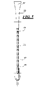
the handling of the catheter by the user may introduce microorganisms onto the
surface of the catheter which can cause infectious problems after being
introduced into the body during catheter insertion. To address this issue,
manufacturers have devised systems that include a protective or barrier sleeve
or
package surrounding the catheter. In this type of product, the catheter tube
is
located in a barrier/package sleeve. The sleeve/package may loosely fit the
diameter of the catheter so that the user may grasp the catheter tube through
the
sleeve to manipulate the catheter, e.g., advance the catheter into the
urethra. In
some products, the distal end of the sleeve may be attached to the drainage
member of the catheter and an insertion aid may be attached to or otherwise
associated with the proximal end of the sleeve.
[0004] One complication of employing a sleeve over a hydrophilic catheter is
how to activate or hydrate the hydrophilic surface of the catheter located
within the
1
CA 03160130 2022-05-03
WO 2021/092388
PCT/US2020/059421
interior cavity of the sleeve.
SUMMARY
[0005] There are several aspects of the present subject matter which may be
embodied separately or together in the devices and systems described and
claimed below. These aspects may be employed alone or in combination with
other aspects of the subject matter described herein, and the description of
these
aspects together is not intended to preclude the use of these aspects
separately
or the claiming of such aspects separately or in different combinations as set
forth
in the claims appended hereto.
[0006] In one aspect, a method of making a urinary catheter product, wherein
the product includes a sleeve defining an inner cavity and a urinary catheter
having a catheter tube located within the inner cavity of the sleeve, the
catheter
tube having an outer hydrophilic surface, the method comprising delivering a
hydration medium through the drainage member and an opening of the catheter
tube into the interior cavity of the sleeve, wherein the hydration medium
contacts
the outer hydrophilic surface of the catheter tube.
[0007] In another aspect, a method of making a urinary catheter product,
wherein the product includes a package defining an inner cavity and a urinary
catheter having a catheter tube located within the inner cavity of the
package, the
catheter tube having an outer hydrophilic surface, the method comprising
delivering a hydration medium through the drainage member and an opening of
the catheter tube into the interior cavity of the package, wherein the
hydration
medium contacts the outer hydrophilic surface of the catheter tube within the
package.
[0008] In another aspect, a system for delivering hydration medium into a
catheter assembly. The system includes a source of hydration fluid and a
nozzle
in communication with the source of hydration fluid. The nozzle is configured
to
dock with a drainage member of a catheter assembly and deliver hydration fluid
into the catheter assembly.
BRIEF DESCRIPTION OF FIGURES
[0009] Fig. 1 is a perspective view of a catheter assembly in accordance with
the
present disclosure;
[0010] Fig. 2 is a perspective view of one embodiment of an insertion aid of
the
assembly of Fig. 1;
-2-
CA 03160130 2022-05-03
WO 2021/092388
PCT/US2020/059421
[0011] Fig. 3 is a perspective view of another embodiment of an insertion aid
of
the assembly of Fig. 1;
[0012] Fig. 4 is a schematic view of one embodiment of a method of making a
hydrophilic sleeved catheter assembly and a hydration medium delivery device
in
accordance with the present disclosure;
[0013] Figs. 5 and 6 are partial cross-sectional view showing the hydration
medium being injected through the drainage member and into the cavity of the
sleeve; and
[0014] Fig. 7 is a side elevational view showing the hydration medium being
injected through the drainage member and into the cavity of a package.
DETAILED DESCRIPTION OF THE ILLUSTRATED EMBODIMENTS
[0015] The embodiments disclosed herein are for the purpose of providing a
description of the present subject matter, and it is understood that the
subject
matter may be embodied in various other forms and combinations not shown in
detail. Therefore, specific embodiments and features disclosed herein are not
to
be interpreted as limiting the subject matter as defined in the accompanying
claims.
[0016] The present disclosure is directed to methods of making a sleeved or
packaged hydrophilic urinary catheter product wherein the urinary catheter is
ready-to-use right out of the outer package. That is, while in the package,
the
hydrophilic outer surface of the catheter tube within the interior cavity of
the sleeve
or package is in a hydrated/activated state, so that the catheter is ready-to-
use
right out of the package.
[0017] Fig. 1 illustrates one embodiment of a catheter assembly 10 in
accordance with present disclosure. The catheter assembly 10 includes an
elongated catheter tube 12 having a proximal end portion 14 and a distal end
portion 16. The proximal end portion 14 of the catheter tube 12 is suitable
for
insertion into a lumen or a passageway of the body, such as the urethra. The
proximal end portion 14 may include drainage holes or eyelets 18 for draining
urine from the bladder. A drainage member 20 may be associated with the distal
end portion 16 of the catheter tube 12. The catheter tube 12 includes an outer
hydrophilic surface that becomes lubricious when hydrated or activated. The
outer surface may be, for example, any suitable hydrophilic coating.
-3-
CA 03160130 2022-05-03
WO 2021/092388
PCT/US2020/059421
[0018] The catheter assembly 10 also includes a sleeve 22, which may be a
protective or barrier sleeve that has a proximal end portion 24 and a distal
end
portion 26. The sleeve 22 surrounds at least a portion of the catheter tube 12
to
separate and enclose the portion of the catheter tube 12 from the outside
environment. In other words, the protective sleeve 22 defines an interior
cavity in
which the catheter tube 12 may be located. In one embodiment, the sleeve 22
extends over the length of the catheter tube 12. Optionally, an insertion aid
28
may be located at the proximal end portion 24 of the sleeve 22. When an
insertion aid 28 is present, the proximal end portion 24 of the sleeve 22 may
be
attached to a barrel or stem 30 of the insertion aid 28, by for example,
welding or
adhesive. The distal end portion 26 of the sleeve 22 may be attached to the
drainage member 20 or the distal end of the catheter tube 12. An insertion aid
may be used with any of the catheter assemblies disclosed herein.
[0019] The sleeve 22 and any of the other sleeves disclosed herein may be
made of a flexible material which may be vapor permeable or vapor impermeable,
depending on the desired use and packaging. The material of the sleeve 22 may
also be liquid impermeable. The sleeve 22 may be formed of any of a variety of
thin, flexible polymeric film materials, such as polyethylene, plasticized
PVC, or
polypropylene, but elastomeric film materials such as polyurethane, and
particularly elastomeric hydrogel materials, may be particularly suitable. The
thickness of the film from which the sleeve 22 is formed may vary considerably
depending on factors such as stretchability and flexibility of the material
selected
but, in general, the thickness may fall within the range of about 10 to 150
microns,
preferably about 13 to 50 microns.
[0020] Referring to Figs. 1, 2 and 3, these figures illustrate exemplary
embodiments of the insertion aids. In Figs. 1 and 2, the insertion aid 28
includes
a proximal end portion 32 that defines an introducer tip 34. The introducer
tip 34
has a proximal end aperture or opening 36 defined by one or more slits between
one or more flexible petals 38. The petals 38 may move, bend and/or
resiliently
deform from the generally closed aperture configuration shown in Figs. 1 and 2
to
an open aperture configuration (not shown) to allow for advancement of the
catheter tube 12 therethrough. The distal end portion of the insertion aid 28
includes a cylindrical or barrel portion 30 that has an opening 40 for
receiving the
catheter tube 12. The insertion aid 28 may also include an intermediate flange
42
-4-
CA 03160130 2022-05-03
WO 2021/092388
PCT/US2020/059421
that may contact the user about the urethra opening and act as a stop to limit
the
insertion of the introducer tip 34.
[0021] Turning to Fig. 3, in this embodiment the insertion aid 28a is a port
29a
that includes a flange 42a surrounding an aperture or opening 34a. The
catheter
tube 12 advances through opening 34a for insertion into the urethra. The
distal
end portion of the port 29a includes a cylindrical or barrel portion 30a that
has an
opening 40a for receiving the catheter tube 12.
[0022] Turning back to Fig. 1, the insertion aid 28, optionally, may be
covered by
a removable protective cap 44. The removable protective cap 44 covers the
insertion aid 28 and may protect the insertion aid 28 from contacting surfaces
and
objects prior to use.
[0023] To use the catheter assembly 10, the user opens and removes the
catheter assembly 10 from an outer package (not shown). For example, the user
opens the package and grasps the catheter tube 12 through the protective
sleeve
.. 22 to handle and manipulate the catheter assembly 10. The user removes
protective cap 44, if one is present. If the catheter assembly 10 includes the
insertion aid 28 shown in Fig. 2, then the user inserts the introducer tip 34
into the
urethra. If the catheter assembly 10 includes the insertion aid 28a shown in
Fig.
3, then the user aligns the opening 34a of the port 29a with the urethral
opening.
.. The user then grasps the catheter tube 12 through the sleeve 22 and
advances
the catheter tube 12 through the insertion aid 28/28a and into and through the
urethra until the eyelets enter the bladder. If the catheter assembly 10 does
not
includes an insertion aid, then the user grasps the catheter tube 12 through
the
sleeve 22 and advances the tip of the catheter tube 12 out of the open end of
the
sleeve 22 and into the urethra. When the eyelets enter the bladder, urine
flows
through the eyelets and catheter tube 12 to drain the bladder.
[0024] In one method of making a sleeved hydrophilic catheter wherein the
hydrophilic surface is in an activated or hydrated state, such as those
described
above, the method includes injecting or delivering a hydration medium into the
interior cavity of the sleeve of the catheter assembly. While in the sleeve,
the
hydration medium contacts the hydrophilic surface of the catheter to at least
partially hydrate or activate the hydrophilic surface, and in one embodiment,
fully
hydrates the hydrophilic surface. Optionally, the hydration medium dwells
within
the sleeve for a selected time period, which may be sufficient to partially or
fully
-5-
CA 03160130 2022-05-03
WO 2021/092388
PCT/US2020/059421
hydrate/activate the hydrophilic surface.
[0025] The hydration medium may be a liquid, foam or a gel. For example, the
hydration medium may be liquid water or an aqueous solution or any other
suitable liquid hydration medium. In one embodiment, the hydration medium may
be an aqueous solution that includes water, glycerol and, optionally, other
additives.
[0026] Optionally, the hydration medium may be a hydration foam that includes
a
liquid containing a mass of gas bubbles on or in the liquid. In one
embodiment,
the hydration foam medium includes, among other components, a liquid, a
surfactant and gas. The liquid may be water or an aqueous solution. The
surfactant may be any suitable foaming agent or surface tension reducing
agent,
such as sodium methyl cocoyl taurate, silicone surfactants or the like. The
gas
may be any suitable gas, such as ambient air, carbon dioxide, nitrogen, etc.
The
gas may be homogenized with the liquid to form a foam. When the hydration
medium is a hydration foam, the hydration medium may be foamed and then
delivered into the sleeve. Alternatively, the hydration medium may be foamed
at
the same time as it is delivered into the sleeve, or may be foamed after it is
delivered into the sleeve.
[0027] In another embodiment, the hydration medium may be a water based gel.
The gel based hydration medium may have a dual function, firstly hydrates
hydrophilic coating and secondly protects retention of water. In one
embodiment,
the gel may be one that liquefies or becomes less viscous when exposed to
radiation and may supplement hydration and lubriciousness of hydrophilic
coating.
For example, the gel may be a gellan gum based gel that is injected into the
sleeve as a gel and then liquefies, breakdowns or becomes less viscous when
the
catheter assembly is exposed to sterilizing radiation, such as e-beam or gamma
radiation. In one embodiment the gel may be a gel that includes 1.5 wt%-2 wt%
of
gellan gum, 1 wt% glycerol and 97 wt%-97.5 wt% of water.
[0028] The hydration medium (liquid or gel) may have an elevated temperature
during injection into the interior cavity of the sleeve. For example, the
hydration
medium may be at a temperature between 15 C-70 C. In another embodiment,
the hydration medium may be at a temperature between 400C-7000 during
injection. Injecting the hydration medium at an elevated temperature may
assist in
the injection process. Additionally, injecting a hydration medium at an
elevated
-6-
CA 03160130 2022-05-03
WO 2021/092388
PCT/US2020/059421
temperature may lessen the time it takes for the hydration medium to
hydrate/activate the hydrophilic surface of the catheter.
[0029] When the hydration medium is a gel, the gel may be injected into the
sleeve as a hot gel solution at an elevated temperature, as discussed above.
The
hot gel solution may partially or substantially hydrate the hydrophilic
coating of the
catheter tube. Optionally, a selected amount of the hot gel solution may be
withdrawn. Alternatively, the method may not include a withdrawal step. The
gel
in the sleeve or remaining in the sleeve after a withdrawal step may cool to
ambient temperatures (e.g., about 23 C or below). When the gel cools, it may
form a thin gel coating, such as a hydrogel coating, at least partially
covering, and
preferably substantially covering, the partially or substantially hydrated
hydrophilic
surface of the catheter tube. Additionally, there may be surplus deposits of
gel
located within the sleeve. Such gel deposits may be gel that is in the sleeve
but
not covering the catheter. Depending on the gel used, the gel may not hydrate
the hydrophilic surface of the catheter while in the gel state, at least
partially
hydrate the hydrophilic surface of the catheter while in the gel state, or
fully
hydrate the hydrophilic surface of the catheter while in the gel state.
Furthermore,
the gel may be a gel that liquefies or becomes less viscous when the catheter
assembly is exposed to sterilizing radiation. For example, after the gel
injection
step and optional withdrawal step, the gel may be covering the hydrophilic
surface
of the catheter and/or may otherwise be located in the sleeve. The catheter
assembly is then placed in a package. The package may then be exposed to
sterilizing radiation wherein the gel liquefies or becomes less viscous.
[0030] Turning now to Fig. 4, this figure provides a schematic representation
of a
fill method that includes an injection system 52 for delivering hydration
medium
into the sleeve 22. The catheter assembly 10 may be docked or otherwise
operatively connected to a hydration medium injection system or machine 52.
The hydration medium injection and system 52 may include a source of hydration
medium 54, which could be a reservoir or tank containing an amount of
hydration
medium 56. The system may include a conduit 58, one end 60 of which is
connected to the source of hydration medium 54, and the end 62 of which is
configured to be connected or docked to the catheter assembly 10 so that
hydration medium 54 can be injected or delivered into the interior cavity of
the
sleeve 22. For example, the end 62 of the conduit 58 may include a nozzle 64
-7-
CA 03160130 2022-05-03
WO 2021/092388
PCT/US2020/059421
configured to be releasably connectable/docked to the drainage member 20. The
system also includes a pump or metering valves or other element 66 for
moving/pumping hydration medium 56 so as to inject hydration medium into the
sleeve 22.
[0031] As discussed above, the method of forming the sleeved activated
hydrophilic catheter may include, injecting a hydration medium into the
interior
cavity of the sleeve 22, wherein the hydration medium comes into contact with
the
outer hydrophilic surface of the catheter tube 12. Referring to Figs. 4 and 5,
there
is shown and described one exemplary embodiment of forming the sleeved
hydrophilic catheter shown in Fig. 1. The nozzle 64 of the injection system is
docked or connected to the drainage member 20. It should be understood that
catheter assembly 10 and the injection system 52 may be in any orientation.
For
example, in Fig. 4, the catheter assembly 10 and the injection system 52 are
shown in an orientation wherein the hydration medium is injected upward
through
catheter 12, while in Fig. 5 the hydration medium is injected downward through
the catheter 12.
[0032] The outer diameter of the nozzle 64 may have a size that generally
corresponds to the inner diameter of the drainage member 20. After the nozzle
64
is dock, hydration medium 56 is injected from the nozzle 64 through the
drainage
member 20 and into the lumen of the catheter tube 12. Referring to Figs. 4 and
6,
the hydration medium 56 flows through the lumen and out of the eyelets 18 of
the
catheter tube 12 and into the sleeve 22 wherein the hydration medium contacts
the hydrophilic surface of the catheter tube 12. Optionally, the catheter tube
12
may also include an opening/eyelet 19 near or proximate the drainage member 20
wherein hydration medium is delivered into the sleeve through this opening 19.
As mentioned above, the hydration medium may be injected at an elevated
temperature.
[0033] After the hydration medium 56 is injected into the sleeve, the catheter
assembly 10 is then placed within an outer package (not shown) and the package
is sealed. The outer package may then be submitted to sterilizing by e-beam or
gamma radiation.
[0034] In one embodiment, the outer package may be made of a gas
impermeable and liquid impermeable material, such as a polymer and aluminum
laminate. Furthermore, the package may be of the type that has a vapor
-8-
CA 03160130 2022-05-03
WO 2021/092388
PCT/US2020/059421
atmosphere or 100% relative humidity within the seal package. For example, the
package may include therein a water compartment that is at least partial
defined
by a vapor permeable, liquid impermeable material. The water within the
compartment may produce a water vapor that permeates through the vapor
permeable, liquid impermeable material to create and/or maintain a hydration
environment within the package. Additionally, when the catheter assembly is
placed in a package having a vapor atmosphere, the sleeve may be vapor
permeable to allow vapor to come into contact with the partially or
substantially
hydrated hydrophilic surface of the catheter tube. This may assist in
maintaining
.. the hydrophilic surface in an activated or hydrated state during storage
and
distribution. Alternatively, when the sleeve is made from a liquid and gas
impermeable material and the interior cavity of the sleeve is sealed off, the
outer
package may be made from a gas permeable material.
[0035] Fig. 7 illustrates another hydrophilic catheter product 100 and method
of
forming the same. The catheter product includes a package 110 and a catheter
tube 12. The package 110 may be any suitable type of package. In the
illustrated
embodiment, the package includes a front sheet 130 and a rear sheet 132 that
are
sealed together about their peripheries. The package includes an internal
cavity
134 that contains the catheter 12. The catheter 12 is similar to that
described
above. The catheter 12 includes a drainage member 20 associated with it distal
end 16, and eyelets 18 associated with it proximal end 14.
[0036] The method of forming the catheter product 100 includes placing the
catheter 12 within the package 110. The drainage member 20 is then docked or
otherwise operatively connected to a hydration medium injection system or
machine 136. The hydration medium injection and system 152 may include a
source (not shown) of hydration medium, which could be a reservoir or tank
containing an amount of hydration medium 156. The system 152 may include a
conduit 138, one end 140 of which is connected to the source of hydration
medium, and the end 142 of which is configured to be connected or docked to
the
drainage member 20. For example, the end 142 of the conduit 138 may include a
nozzle 144 configured to be releasably connectable/docked to the drainage
member 20.
[0037] After the nozzle 144 is dock, hydration medium 146 is injected from the
nozzle 144 through the drainage member 20 and into the lumen of the catheter
-9-
CA 03160130 2022-05-03
WO 2021/092388
PCT/US2020/059421
tube 12. The hydration medium 146 flows through the lumen and out of the
eyelets 18 of the catheter tube 12 and into the interior 134 of the package
110
wherein the hydration medium 146 contacts the hydrophilic surface of the
catheter
tube 12. Optionally, the catheter tube 12 may also include an opening/eyelet
19
near or proximate the drainage member 20, wherein hydration medium 156 is
delivered into the package through this opening 19.
[0038] After the hydration medium 56 is injected into the package, the package
is sealed. The outer package may then be submitted to sterilizing by e-beam or
gamma radiation.
[0039] It will be understood that the embodiments described above are
illustrative of some of the applications of the principles of the present
subject
matter. Numerous modifications may be made by those skilled in the art without
departing from the spirit and scope of the claimed subject matter, including
those
combinations of features that are individually disclosed or claimed herein.
For
these reasons, the scope hereof is not limited to the above description but is
as
set forth in the following claims, and it is understood that claims may be
directed
to the features hereof, including as combinations of features that are
individually
disclosed or claimed herein.
-10-