Note: Descriptions are shown in the official language in which they were submitted.
CA 03160691 2022-05-07
WO 2021/087949 PCT/CN2019/116582
REFERENCE SIGNALING DESIGN AND CONFIGURATION
TECHNICAL DOMAIN
This patent document is directed generally to wireless communications.
BACKGROUND
Mobile communication technologies are moving the world toward an increasingly
connected and networked society. The rapid growth of mobile communications and
advances in
technology have led to greater demand for capacity and connectivity. Other
aspects, such as
energy consumption, device cost, spectral efficiency, and latency are also
important to meeting
the needs of various communication scenarios. Various techniques, including
new ways to
provide higher quality of service, are being discussed.
SUMMARY
This document discloses methods, systems, and devices related to digital
wireless
communication, and more specifically, to techniques related to implementing
SCG suspension.
In one exemplary aspect, a method for wireless communication includes
detecting
data to be transmitted via a group of cells. The method also includes
transmitting a first message
initiating activation of the group of cells to a network node.
In another exemplary aspect, a method for wireless communication includes
receiving
a first message providing an indication to activate a serving cell included in
a group of cells from
a network node. The method also includes activating the serving cell of the
group of cells based
on the first message.
In another exemplary aspect, a method for wireless communication includes
receiving
a channel measurement configuration from a secondary network node. The method
also includes
configuring a reporting configuration relating to channel measurements for a
serving cell
included in a group of cells based on the channel measurement configuration.
In another exemplary aspect, a wireless communications apparatus comprising a
processor is disclosed. The processor is configured to implement a method
described herein.
In yet another exemplary aspect, the various techniques described herein may
be
embodied as processor-executable code and stored on a computer-readable
program medium.
1
Date Recue/Date Received 2022-05-07
CA 03160691 2022-05-07
WO 2021/087949 PCT/CN2019/116582
Some embodiments may preferably implement the following solutions, written in
a
clause-format.
L A solution for wireless communication, comprising: detecting, by a terminal,
data
to be transmitted via a group of cells; and transmitting, by the terminal, a
first message initiating
activation of the group of cells to a network node.
2. The solution of clause 1, further comprising: receiving, by the terminal, a
second
message from the network node including an indication to activate the group of
cells; and
activating, by the terminal, the group of cells as specified in the second
message.
3. The solution of clause 2, wherein activating the group of cells includes
transitioning the serving cell of the group of cells from dormancy behavior to
non-dormancy
behavior.
4. The solution of clause 2, wherein activating the group of cells activates
the
serving cell of the group of cells from a deactivated state to an activated
state.
5. The solution of clause 1, wherein the first message includes any of a radio
resource control (RRC) message and a medium access control (MAC) control
element (CE).
6. The solution of clause 1, wherein the network node includes a master node
(MN).
7. The solution of clause 1, further comprising: initiating, by the teiminal,
a physical
random-access channel (PRACH) on a primary secondary cell (PSCell) of the
group of cells.
8. The solution of clause 7, further comprising: receiving, by the terminal, a
response message from a secondary node (SN) that indicates a serving cell
included in the group
of cells to be transited from dormancy behavior to non-dormancy behavior, or
activated from
deactivated state.
9. The solution of clause 1, wherein the first message is indicative of a data
buffer
size and a logical channel group.
10. The solution of clause 1, further comprising: mapping, by the terminal,
the data to
a data radio bearer (DRB).
11. The solution of clause 10, wherein the DRB includes a bearer for the group
of
cells indicating that the DRB is mapped to the group of cells and includes a
leg for the group of
cells.
12. The solution of clause 10, wherein the DRB includes a split bearer
indicating that
the DRB includes a master cell group (MCG) leg and a leg for the group of
cells.
2
Date Recue/Date Received 2022-05-07
CA 03160691 2022-05-07
WO 2021/087949 PCT/CN2019/116582
13. A solution for wireless communication, comprising: receiving, by a
terminal, a
first message providing an indication to activate a serving cell included in a
group of cells from a
network node; and activating, by the terminal, the serving cell of the group
of cells based on the
first message.
14. The solution of clause 13, wherein activating the group of cells includes
transitioning the serving cell of the group of cells from dormancy behavior to
non-dormancy
behavior.
15. The solution of clause 13, wherein activating the group of cells includes
activating the serving cell of the group of cells from a deactivated state to
an activated state.
16.The solution of clause 13, wherein the network node includes a master node
(MN).
17. The solution of clause 16, wherein the MN is configured to receive a
second
message including the serving cell to be activated from dormancy behavior to
non-dormancy
behavior and includes dedicated physical random-access channel (PRACH)
resources from a
secondary node (SN), the first message including information included in the
second message.
18. The solution of clause 17, further comprising: transitioning, by the
terminal, the
serving cell from dormancy behavior to non-dormancy behavior according to the
information
included in the second message.
19. The solution of clause 13, wherein the first message includes any of a
radio
resource control (RRC) message, a medium access control (MAC) control element
(CE), and
downlink control information (DCI).
20. The solution of clause 16, wherein the MN is configured to determine
whether to
activate the group of cells.
21. The solution of clause 13, further comprising: receiving, by the terminal,
an RRC
reconfiguration message from the network node; and responsive to determining
that the RRC
reconfiguration message includes a configuration for the group of cells,
activating the group of
cells according to the configuration for the group of cells.
22. A solution for wireless communication, comprising: receiving, by a primary
network node, a channel measurement configuration from a secondary network
node; and
configuring, by the primary network node, a reporting configuration relating
to channel
measurements for a serving cell included in a group of cells based on the
channel measurement
configuration.
3
Date Recue/Date Received 2022-05-07
CA 03160691 2022-05-07
WO 2021/087949 PCT/CN2019/116582
23. The solution of clause 22, wherein the channel measurement includes any of
a
channel state information (CSI) measurement and a channel quality indicator
(CQI)
measurement.
24. The solution of clause 22, further comprising: sending, by the primary
network
node, the configured reporting configuration to the secondary network node,
the secondary
network node configured to send a radio resource control (RRC) message to a
terminal that
includes channel measurement resources on the serving cell of the group of
cells and the channel
reporting configuration on a serving cell of a master group of cells.
25. The solution of clause 22, further comprising: receiving, by the primary
network
node, a report that includes the channel measurements for the serving cell of
the group of cells.
26. The solution of clause 25, further comprising: forwarding, by the primary
network
node, the received report that includes the channel measurements for the
serving cell of the group
of cells to the secondary network node.
27. The solution of clause 26, wherein the received report that includes the
channel
measurements for the serving cell of the group of cells is forwarded by the
primary network node
to the secondary network node via a control plane (CP) message.
28. The solution of clause 26, wherein the received report that includes the
channel
measurements for the serving cell of the group of cells is forwarded by the
primary network node
to the secondary network node via a user plane (UP) message.
29. The solution of clause 22, wherein the reporting configuration configured
by the
primary network node is valid when the group of cells is suspended.
30. The solution of clause 26, wherein the received report including the
channel
measurements for the serving cell of the group of cells forwarded to the
secondary network node
includes CSI reporting information that includes a cell identifier and
reporting content.
31. An apparatus for wireless communication comprising a processor that is
configured to carry out the solution of any of solutions 1 to 30.
32. A non-transitory computer readable medium having code stored thereon, the
code
when executed by a processor, causing the processor to implement a solution
recited in any of
solutions 1 to 30.
The details of one or more implementations are set forth in the accompanying
attachments, the drawings, and the description below. Other features will be
apparent from the
4
Date Recue/Date Received 2022-05-07
CA 03160691 2022-05-07
WO 2021/087949 PCT/CN2019/116582
description and drawings, and from the clauses.
BRIEF DESCRIPTION OF THE DRAWINGS
FIG. 1 is a block diagram of an example set of states for a serving cell.
FIG. 2 is a block diagram of an example transition between behavior of a
serving cell.
FIG. 3 is a block diagram of a MN, SN, and UE.
FIG. 4 is an example signaling process for forwarding an RRC message to an SN.
FIG. 5 is an example signaling process of a RACH procedure.
FIG. 6 is an example signaling process for activating an SCG responsive to SN
initiation of the SCG activation.
FIG. 7 is an example signaling process for a MN initiating a SCG activation
procedure.
FIG. 8 is an example signaling process for indicating a channel measurement
reporting configuration according to a first option.
FIG. 9 is an example signaling process for indicating a channel measurement
reporting configuration according to a second option.
FIG. 10 is an example signaling process for forwarding channel measurement
reporting.
FIG. 11 is an example method for implementing SCG suspension.
FIG. 12 shows an example of a wireless communication system where techniques
in
accordance with one or more embodiments of the present technology can be
applied.
FIG. 13 is a block diagram representation of a portion of a hardware platform.
DETAILED DESCRIPTION
Section headings are used in the present document only for ease of
understanding and
do not limit scope of the embodiments to the section in which they are
described. Furthermore,
while embodiments are described with reference to 5G examples, the disclosed
techniques may
be applied to wireless systems that use protocols other than 5G or 3GPP
protocols.
The development of the new generation of wireless communication ¨ 5G New Radio
(NR) communication ¨ is a part of a continuous mobile broadband evolution
process to meet the
requirements of increasing network demand. NR will provide greater throughput
to allow more
Date Recue/Date Received 2022-05-07
CA 03160691 2022-05-07
WO 2021/087949 PCT/CN2019/116582
users connected at the same time. Other aspects, such as energy consumption,
device cost,
spectral efficiency, and latency are also important to meeting the needs of
various
communication scenarios.
Overview
In 3GPP NR, dormancy behavior of a serving cell is introduced to save UE
power.
When a serving cell is in dormancy behavior, the UE may generally not be
required to monitor
PDCCH on the serving cell, but the UE may keep channel state information (CSI)
measurement
on this serving cell to maintain automatic gain control (AGC) and fine
time/frequency
synchronization to minimize the delay used for transition from dormancy
behavior to non-
dormancy behavior (or a normal active state).
In many cases (e.g., both NR an E-UTRAN), a serving cell can be in any of an
activated, deactivated, or dormant state. A UE can perform downlink and uplink
activities on a
serving cell in activated state. No downlink or uplink transmission may be
performed on a
serving in a deactivated state. The UE may perform channel measurements on a
serving cell in
dormant state.
FIG. 1 is a block diagram 100 of an example set of states for a serving cell.
As shown
in FIG. 1, the serving cell can transition between an activated state 102, a
deactivated state 104,
and a dormant state 106.
In many cases, the dormancy behavior of a serving cell may be implemented by
configuring a bandwidth part (BWP) without physical downlink control channel
(PDCCH)
configuration. Dormancy behavior may only be applied to a serving cell in an
activated state.
This BWP may be referred to a dormant BWP of the serving cell. When the active
BWP of a
serving cell is the dormant BWP, the serving cell may be in dormancy behavior.
Otherwise, the
serving cell may be in non-dormancy behavior. The base station (BS) may
transition a serving
cell to dormancy behavior by Li signaling (i.e. DCI).
FIG. 2 is a block diagram 200 of an example transition between behavior of a
serving
cell. As shown in FIG. 2, the serving cell in dormancy behavior 202 can
transition to non-
dormancy behavior 204. Similarly, the serving cell in non-dormancy behavior
204 can transition
to dormancy behavior 202.
In many cases, a UE can be configured with a master cell group (MCG) and a
secondary cell group (SCG). MCG and SCG may comprise a group of serving cells.
A MCG
6
Date Recue/Date Received 2022-05-07
CA 03160691 2022-05-07
WO 2021/087949 PCT/CN2019/116582
may be anchored on the network node or BS, which may be referred to as a
master node (MN).
SCG may be anchored on the network node or BS, which may be referred to as a
secondary node
(SN). MN and SN may communicate via inter-node interfaces called Xn or X2
interface in NR
and E-UTRAN respectively. The primary serving cell in MCG may be a primary
cell (PCell) and
the primary serving cell in SCG may be a primary secondary cell (PSCell).
FIG. 3 is a block diagram 300 of a MN 302, SN 304, and UE 306. As shown in
FIG.
3, the MN 302 may communicate to a SN 304 via an X2/Xn interface. The MN 302
may
communicate to a UE 306 via a radio interface MCG. The SN 304 may communicate
with the
UE 306 via a radio interface SCG.
Further, in many cases, a PSCell may always be activated if it is configured.
Accordingly, it may be beneficial to transition SCG or PSCell to suspension in
some cases that
there may be no need for data transmission on the SCG to save UE power in when
UE is in an
RRC CONNECTED state.
System overview
The present embodiments may provide methods to implement SCG suspension. The
UE may initiate activation of an SCG upon UL data arrival. The UE may transmit
a RRC/MAC
CE message to a MN. The UE may initiate PRACH to a PSCell. In some
embodiments, a RACH
Msg4/Msg2 may indicate which serving cell is to be activated to non-dormancy.
A data buffer
size or LCG may be included in a message transmitted by the UE as described
herein.
In some embodiments, the SCG may be activated by the network. In one case, an
MN
may initiate SCG activation. This may be performed via a SN modification
procedure. The SN
modification procedure may include the SN indicating a dedicate PRACH and
which serving cell
is to be activated/transitioned from dormancy behavior. The MN may generate a
message (RRC,
MAC CE, or DCI) to activate SCG, where the message may include which serving
cell is to be
activated.
In another case, the SN may initiate SCG activation. The SN may indicate a MN
activation request that includes which serving cell is to be
activated/transitioned from dormancy
behavior and dedicated PRACH resources. The MN may generate an RRC or MAC CE
or DCI
to activate the SCG.
In another case, the UE may autonomously activate the SCG upon RRC
reconfiguration. If RRC reconfiguration contains SCG configuration, the UE may
activate the
7
Date Recue/Date Received 2022-05-07
CA 03160691 2022-05-07
WO 2021/087949 PCT/CN2019/116582
PSCell and apply the configuration.
The present embodiments may relate to reporting channel measurements. To
configure channel measurement reporting, the SN may send to the MN a serving
cell index list,
measurement resource configuration, or resource config-ID, and reporting
quantity. The MN
may configure channel measurement reporting resources and associate a
reporting resource and a
measurement resource.
In a first case, the MN may send the reporting configuration to the SN. The SN
may
then generate RRC to the UE. In a second case, the MN may send the reporting
configuration to
the UE directly. The RRC message may be generated by the MN that can be used
to suspend
SCG.
The configuration may only be valid when SCG is suspended. The suspension of
SCG may start upon a RRC message/MAC CE/DCI that suspended the SCG. The
suspension of
SCG may stop upon SCG activation via RRC/MAC CE/DCl/timer expiration.
A MN may forward channel measurement reporting to the SN. This may be
performed via a control plane (CP), where an Xn/X2 message may be used for
forwarding CSI
reporting. This may be performed via a user plane (UP), where an Xn/X2 tunnel
may be used for
forwarding CSI reporting. The CSI reporting may include a cell ID and
reporting content as well
as a list of reporting sorted by a cell ID value.
In the present embodiments, a suspended SCG may mean that a PSCell is in
deactivated state or dormancy behavior. The suspended SCG may mean that PSCell
and all other
serving cells of SCG are in deactivated state. The suspended SCG may mean that
PSCell is in
dormancy behavior, and other serving cells are in dormancy behavior or
deactivated state. The
suspended SCG may mean that PSCell is in dormant state, other SCG serving
cells are in
dormant state or deactivated state.
In the present embodiments, activation of SCG may mean a transition of at
least the
PSCell from dormancy behavior to non-dormancy behavior if it is in dormancy
behavior, or
activating at least the PSCell from deactivated state if it is in a
deactivated or dormant state.
Example Embodiment 1
Example Embodiment I may relate to the UE initiating a SCG activation
procedure.
Upon uplink data reception by a UE, the uplink data may be mapped on a data
radio bearer
(DRB). The DRB may be a SCG bearer, where the DRB may be mapped on the SCG and
has at
8
Date Recue/Date Received 2022-05-07
CA 03160691 2022-05-07
WO 2021/087949 PCT/CN2019/116582
least one SCG leg. The DRB may be a split bearer, where the DRB has at least a
MCG leg and at
least a SCG leg.
Alternatively, upon uplink RRC message is to be transmitted via a signaling
radio
bearer (SRB). The SRB may be mapped on SCG only. In particular, the SRB may be
a SRB3
established on SCG. The SRB may be a split SRB, where the SRB may include at
least a MCG
leg and at least a SCG leg.
The UE may initiate SCG activation procedure according any of the following
methods as described herein.
Method 1
Method 1 may relate to a UE transmitting a RRC message or a MAC CE, via MCG to
the BS. In some embodiments, the RRC message may include the information of a
DRB which
has uplink data to be transmitted or information of a SRB which has uplink RRC
message to be
transmitted. In some embodiments, the information includes a DRB ID and data
buffer size
information that indicate a total data volume available for transmission for
the DRB. In some
embodiments, the information may include a SRB ID.
In some embodiments, an RRC message may include a logical channel group ID
(LCID) and the data buffer size information that can indicate the total amount
of data available
for transmission of the logical channel group.
The MAC CE may be identified with a unique (LCID) defined by specification or
previously configured by a BS. The LCID may indicate that a MAC CE is used to
transmit data
buffer size information for SCG or to notify the request of uplink
transmission via SCG. The
MAC CE may include a logical channel group information and corresponding data
buffer size
information.
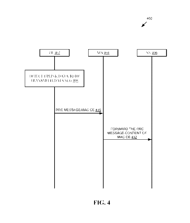
FIG. 4 is an example signaling process 400 for forwarding an RRC message to an
SN.
The UE 402 may determine that there is uplink data or message to be
transmitted via SCG (block
408). The UE 402 may send an RRC message/MAC CE 410 to MN 404. Upon reception
of the
RRC message or the MAC CE, the MN may initiate a SCG activation procedure as
described in
greater detail below.
The MN 404 may forward the received RRC message 412 or the MAC CE to the SN
406. In some embodiments, the MN 404 may forward the content of the RRC
message or the
MAC CE to the SN or indicate to the SN 406 a SCG activation request.
9
Date Recue/Date Received 2022-05-07
CA 03160691 2022-05-07
WO 2021/087949 PCT/CN2019/116582
Method 2
Method 2 generally relates to initiating a random-access channel (RACH)
procedure
via SCG (PSCell). The UE may initiate a RACH procedure. The RACH procedure may
include
one of a 4 step RACH procedure or a 2 step RACH procedure.
FIG. 5 is an example signaling process 500 of a RACH procedure. As shown in
FIG.
5, a UE 502 may determine that there is uplink data or a message to be
transmitted via SCG
(block 508).
The UE 502 may send a preamble message 510 (msg 1) to the SN 506. The SN 506
may send a random access response (RAR) message 512 (m5g2) to the UE 502.
The UE 502 may send a RACH msg3 514 to SN 506. Msg3 can include a UE ID,
LCG ID and data buffer size, or a DRB ID list or a SCG activation request.
SN 506 may send RACH msg4 516 to the UE 502. Msg4 can include serving cell
information of a serving cell to be activated/transitioned to non-dormancy
behavior.
SN 506 may send a message 518 to MN 504 indicating that SCG is activated.
In msg3 of a 4 step RACH procedure and in message 1 of a 2 step RACH
procedure,
a UE ID may be included to identify the UE.
In some embodiments, the UE ID may be the C-RNTI allocated to the UE by the
SN.
In some embodiments, message 3 and/or message 1 may further include a DRB ID
and the data
buffer size information which indicate the total data volume available for
transmission for this
DRB. In some embodiments, the information may include a SRB ID or an
indication that there is
RRC message to be transmitted via SCG.
In some embodiments, the message 3 and/or message 1 may contain a logical
channel
group ID, and the data buffer size information which indicate the total amount
of data available
for transmission of this logical channel group. In some embodiments, the
message 3 and message
1 may include an indication to request activating SCG. In response to
receiving message 3 and
message 1 respectively, the SN may indicate to the UE via message 4 and
message 2,
respectively.
In some embodiments, a bitmap may be generated to indicate the serving cell or
cell
group to be activated or transited from dormancy behavior to non-dormancy
behavior. The
bitmap may include one bit per SCG serving cell or one bit per cell group. In
some embodiments,
the bitmap may be included in the DCI that schedules the message 4 or message
2.
Date Recue/Date Received 2022-05-07
CA 03160691 2022-05-07
WO 2021/087949 PCT/CN2019/116582
In some embodiments, a list of SCG serving cell index or a list of serving
cell ID and
corresponding serving cell state of each SCG serving cell may be included.
Upon reception of
message 4 or message 2, the UE may activate a serving cell or transit a
serving cell from
dormancy to non-dormancy according to received message 4 or message 2. In some
embodiments, the SN may inform MN that the SCG is activated.
The UE can indicate SN there is uplink data to be transmitted directly, but
not via
MN. One benefit of this method may include the delay of SCG activation can be
reduced
compared to other options. In the 2 step RACH case, there may be no message 3
and message 4,
the content in message 3 and message 4 in following case can be carried in
message 1 and
message 2.
Example Embodiment 2
Example Embodiment 2 may generally relate to an SN initiating a SCG activation
procedure. In many cases, the SN may initiate SCG activation by indicating MN
that there is
downlink data arrival via an interface between MN and SN.
In the present embodiments, when an SN initiates SCG activation procedure to
transit
SCG from suspended to normal state, the SN can provide an indication to the
MN. This
indication may include dedicated PRACH resource information for the UE to
perform RACH
procedure on a SCG serving cell. The dedicated PRACH resource may be a
contention free
RACH resource in a SCG serving cell. This dedicated PRACH resource may be
forwarded to UE
by MN to speed up synchronization with SN.
FIG. 6 is an example signaling process 600 for activating an SCG responsive to
SN
initiation of the SCG activation. The SN 606 may send a message 608 to the MN
604 indicating
to the MN the serving cells to be activated/transitioned to non-dormancy. The
MN 604 may send
an RRC message/MAC CE/DCI message 610 to activate the SCG. The UE 602 can
activate the
SCG 612.
In some embodiments, the indication to the MN may include information of a
serving
cell which is to be transited to non-dormancy behavior. In other embodiments,
the indication to
the MN may include information of serving cell which is to be activated from
deactivated state.
In other embodiments, the indication to the MN may include an indication that
SCG is to be
activated from a suspended state.
The SN may indicate the above information to the MN via a RRC message, (e.g.,
11
Date Recue/Date Received 2022-05-07
CA 03160691 2022-05-07
WO 2021/087949 PCT/CN2019/116582
RRCReconfiguration), or an inter-node message IE contained in the message
transmitted from
SN to MN (e.g., CG-config defined in NR specification).
Upon reception of the indication from SN, the MN may transmit a RRC message
(e.g.
RRCReconfiguration), a MAC CE, or a DCI to inform the UE to activate SCG
(i.e., transition
the SCG from suspended state). In the RRC message or MAC CE used to activate
SCG,
dedicated PRACH resource indicated from SN may be contained. In the RRC
message, MAC CE,
or the DCI used to activate SCG, the serving cell information to be transited
from dormancy
behavior, or the serving cell information to be activated may be contained.
The serving cell information may be a bitmap where one bit is used to
represent a
serving cell, or a list of serving cell index, or a list of serving cell ID.
Upon reception of the RRC
message, MAC CE, or DCI, the UE may activate SCG serving cell or transition a
SCG serving
cell from dormancy to non-dormancy.
In the present embodiments, the SN can provide dedicated PRACH resource to the
UE along with the SCG activation signaling. SN can also indicate which SCG
serving cell is to
be activated or transitioned from dormancy behavior. Accordingly, the delay
used for SCG
activation can be reduced.
Example Embodiment 3
Example Embodiment 3 may generally relate to a MN initiating a SCG activation
procedure. In many cases, a MN may initiate SCG activation according to its
decision. In the
present embodiments, the MN may initiate SCG activation procedure by
indicating SN via a
message via interface between MN and SN. In some embodiments, the MN may
initiate SCG
activation by SN modification procedure as defined in 3GPP specification. The
SN modification
request message may include an indication to request SCG activation.
FIG. 7 is an example signaling process 700 for a MN initiating a SCG
activation
procedure. The MN 704 may decide to activate SCG (block 708). The MN 704 may
send a SN
modification request 710 to the SN 706 indication a request to activate SCG.
The SN 706 may
send a SN modification response 712 to the MN 704 that includes the serving
cells to be
activated or transitioned to non-dormancy. The MN 704 may send an RRC
message/MAC
CE/DCI 714 to the UE 702 to activate the SCG. The UE 702 may activate the SCG
716
responsive to receiving the RRC message/MAC CE/DCI 714.
Upon reception of a SN modification request message, SN may respond with a SN
12
Date Recue/Date Received 2022-05-07
CA 03160691 2022-05-07
WO 2021/087949 PCT/CN2019/116582
modification response message which may include the dedicated PRACH resource
for the UE
perform RACH procedure on a SCG serving cell. The dedicated PRACH resource may
be
contention free RACH resource in a SCG serving cell. This dedicated PRACH
resource may be
forwarded to UE by MN to speed up synchronization with SN.
The SN modification response message may include information of serving cell
which is to be transited to non-dormancy behavior or information of serving
cell which is to be
activated from deactivated state.
Upon reception of the indication from SN, the MN transmit a RRC message (e.g.
RRCReconfiguration), or a MAC CE, or a DCI to inform UE to activate SCG (i.e.,
transition
SCG from a suspended state).
In the RRC message or MAC CE used to activate SCG, dedicated PRACH resource
indicated from SN may be contained. In the RRC message, MAC CE, or the DCI
used to activate
SCG, the serving cell information to be transited from dormancy behavior, or
the serving cell
information to be activated may be contained.
The serving cell information may be a bitmap which one bit is used to
represent a
serving cell, or a list of serving cell index, or a list of serving cell ID.
Upon reception of the RRC
message, MAC CE or DCI, the UE activate SCG serving cell, or transit a SCG
serving cell from
dormancy to non-dormancy.
At least in one of following case, the MN may want to activate SCG when there
is
split DRB or SRB to be configured. The MN may want to activate SCG when there
is a DRB
terminated on SN to be configured. The MN may want to activate SCG when there
is data to be
transmitted via a DRB that is an MN-terminated SCG bearer, or MN-terminated
spit bearer.
Accordingly, there may be a need for the MN initiated SCG activation
procedure. The
MN can initiate SCG activation by reuse current procedure as much as possible.
Example Embodiment 4
Example Embodiment 4 may generally relate to UE activation of a SCG upon
reception of RRC reconfiguration information. Upon reception of a RRC
reconfiguration
message from BS, if the RRC reconfiguration message contains reconfiguration
of SCG, the UE
may activate SCG autonomously and apply the reconfiguration.
In some embodiments, if the reconfiguration involves PSCell, the UE applies
the
reconfiguration and activates PSCell autonomously.
13
Date Recue/Date Received 2022-05-07
CA 03160691 2022-05-07
WO 2021/087949 PCT/CN2019/116582
In some embodiments, if the RRC reconfiguration message contains IE
reconfiguration WithSync or mobilityControlInfo as defined in 3GPP
specification, the UE can
apply the reconfiguration and activate at least PSCell.
In some embodiments, if the reconfiguration involves physical layer
configuration of
a SCG serving cell (e.g., add or modify serving cell or configuration of
physical layer of a
serving cell), the UE activates at least the PSCell and the involved SCG
serving cell.
This may provide an opportunity for the UE to verify whether the new SCG
configuration is valid.
Example Embodiment 5
Example Embodiment 5 may generally relate to channel measurement configuration
and reporting. The channel measurement can include CSI measurement or CQI
measurement. In
many cases, the SN may configure channel measurement configuration for the UE
and indicate
the configuration via a RRC message transmitted via SCG directly to UE or a
RRC message
encapsulated in another RRC message generated by MN. In either case, the SN
and MN may
configure a channel measurement configuration for MCG serving and SCG serving
cell,
respectively. The channel reporting for a SCG serving cell may be reported via
SCG serving
cells only.
In many cases, when SCG is in a suspended state and channel measurement
reporting
is to be performed, the channel measurement reporting for serving cell of SCG
may be
transmitted via MCG.
In the present embodiments, to enable channel measurement reporting via MCG
for
serving cells of SCG, the SN can indicate to MN a list of channel measurement
configuration. A
channel measurement configuration may include a serving cell index that can be
used to identify
a SCG serving cell for which the channel measurement configuration is
configured. The channel
measurement configuration may include a channel measurement reporting type.
The channel
measurement reporting type may be periodic on PUCCH, semi-persistent on PUCCH,
semi-
persistent on PUSCH, aperiodic on PUSCH.
The CSI/CQ1 measurement configuration may include report quantity information
used to indicate the needed measurement quantity for reporting. The channel
measurement
configuration may include a channel measurement resource information.
In some embodiments, the channel measurement resource information may be a set
of
14
Date Recue/Date Received 2022-05-07
CA 03160691 2022-05-07
WO 2021/087949 PCT/CN2019/116582
channel measurement resource configuration. The channel measurement resource
configuration
may include a BWP ID which indicates a DL BWP which the channel measurement
resource for
measurement are located. The channel measurement resource configuration may
further include
a resource type indication.
In some embodiments, the channel measurement resource information may be a
channel measurement resource configuration ID that identifies a channel
measurement resource
configuration which is configured by the SN to UE beforehand.
The SN may provide MN above information via a RRC message (e.g.
RRCReconfiguration), or an inter-node message IE contained in the message
transmitted from
SN to MN (e.g. CG-config as defined in NR specification).
The MN may configure channel measurement reporting configuration for a SCG
serving cell. The channel measurement reporting configuration may include a
channel
measurement reporting ID. The channel measurement reporting configuration may
further
include a set of reporting resources configuration.
In some embodiments, the reporting resource configuration may include an MCG
serving cell index on which the reporting resource is located, a reporting
type information, and
PUCCH or PUSCH resource configuration for reporting.
In some embodiments, the reporting resource configuration may include a uplink
SPS
resource configuration, or a configured grant configuration.
In a first option, the MN may indicate the channel measurement reporting
configuration to the SN. FIG. 8 is an example signaling process 800 for
indicating a channel
measurement reporting configuration according to a first option. The SN 806
may send a
Cchannel measurement configuration 808 to a MN 804. The channel measurement
configuration 808 can include a SCG serving cell index, resource
configuration, reporting
quantity, etc.
The MN 804 can configure channel measurement reporting configuration for
channel
measurement of a SCG serving cell (block 810). The MN 804 may send a channel
measurement
reporting configuration for a channel measurement on a SCG serving cell 812 to
the SN 806.
The SN 806 can send an RRC message 814 to the UE 802. The RRC message 814
may include channel measurement resources on a SCG serving cell and channel
measurement
reporting configuration on a MCG serving cell.
Date Recue/Date Received 2022-05-07
CA 03160691 2022-05-07
WO 2021/087949 PCT/CN2019/116582
The SN may indicate the channel measurement reporting configuration for the
SCG
serving cell to the UE via a RRC message generated by the SN. The channel
measurement
reporting configuration may be associated with the channel measurement
resource configuration
ofthe SCG serving cell. In the RRC message, the SN may indicate the channel
measurement
reporting resource is located on a MCG serving cell. In the RRC message, the
SN may indicate
the channel measurement resouce configuration and its associated channel
measurement
reporting configuration ID which is allocated by the MN for the SCG serving
cell.
In a second option, the MN may indicate the channel measurement reporting
configuration to the UE directly via a RRC message generated by the MN. FIG. 9
is an example
signaling process 900 for indicating a channel measurement reporting
configuration according to
a second option. The SN 906 may send a channel measurement configuration 908
to a MN 904.
The channel measurement configuration 908 can include a SCG serving cell
index, resource
configuration, reporting quantity, etc.
The MN 904 can configure channel measurement reporting configuration for
channel
measurement of a SCG serving cell (block 910). The MN 904 can send an RRC
message 912 to
the UE 902. The RRC message 912 may include channel measurement resources on a
SCG
serving cell, channel measurement reporting configuration on a MCG serving
cell.
The MN may indicate the channel measurement reporting configuration to the UE
directly via a RRC message generated by the MN. The channel measurement
reporting
configuration may be associated with the channel measurement resource
configuration of the
SCG serving cell. In the RRC message, the MN may indicate the channel
measurement reporting
configuration is associated with a SCG serving cell. In the RRC message, the
MN may indicate
the channel measurement reporting configuration and its associated channel
measurement
resource configuration ID that is allocated by the SN for the SCG serving
cell.
In any of the first or second option, the RRC message may be used to suspend
SCG.
The UE may apply the channel measurement reporting configuration upon
reception
of a RRC message including the channel measurement reporting configuration.
The application
may stop upon reception of a RRC message which release the channel measurement
reporting
configuration.
The UE may apply the channel measurement reporting configuration upon starting
to
apply upon reception of a RRC message, a MAC CE or a DCI which indicate the UE
to suspend
16
Date Recue/Date Received 2022-05-07
CA 03160691 2022-05-07
WO 2021/087949 PCT/CN2019/116582
SCG (i.e. upon suspending SCG). The application may stop upon reception of a
RRC message, a
MAC CE or a DCI that indicates the UE to activate SCG.
The UE may apply the channel measurement reporting configuration upon starting
to
apply upon autonomous transition SCG to suspended due to a timer expiration.
Reporting channel measurement results for a SCG serving cell via MCG may be
performed. In some embodiments, the UE performs channel measurement reporting
according to
indicated channel measurement reporting configuration. In some embodiments, if
the channel
measurement reporting configuration includes PUCCH or PUSCH resource, the UE
perform
channel measurement reporting on PUCCH or PUSCH according to the
configuration. In some
embodiments, if the channel measurement reporting configuration includes
uplink SPS resource
or configured grant resource, the UE performs channel measurement reporting
using the uplink
SPS resource or configured grant resource. In some embodiments, the channel
measurement
reporting is performed by transmitting a RRC message, or a MAC CE. The RRC
message and
the MAC CE includes channel measurement reporting for a list of SCG serving
cells.
Upon reception of channel measurement reporting for SCG serving cell from UE,
the
MN may forward the channel measurement reporting to SN via interface between
MN and SN. If
channel measurement reporting is transmitted via a RRC message from the UE,
the MN may
forward the RRC message to the SN.
If channel measurement reporting is transmitted via a MAC CE, or on PUCCH, or
on
PUSCH, from the UE, in some implementation, the MN may forward the reporting
content via a
control plane message via interface between MN and SN. In some embodiments,
the MN
forwards the reporting content via a user plane message via interface between
MN and SN. A
user plane tunnel is allocated for forwarding the reporting contents.
In any of the present embodiments, the forwarded reporting content may include
a list
of SCG serving cell index and related reporting, or the forwarded reporting
content may include
a list of reporting which is sorted according to its associated SCG serving
cell index, according
to its associated channel measurement reporting ID.
FIG. 10 is an example signaling process 1000 for forwarding channel
measurement
reporting results. The UE 1002 may send a channel measurement reporting
message 1008 for a
SCG serving cell to a MN 1004. The MN 1004 may forward the channel measurement
reporting
information 1010 to a SN 1006. The channel measurement reporting information
1010 may
17
Date Recue/Date Received 2022-05-07
CA 03160691 2022-05-07
WO 2021/087949 PCT/CN2019/116582
include a CP message or a UP message.
In the present embodiment, the MN and SN can cooperate in channel measurement
reporting configuration, and channel measurement reporting. Accordingly, the
channel
measurement reporting for SCG serving cell via MCG may be possible.
FIG. 11 is an example method 1100 for implementing SCG suspension. The method
may include detecting, by a terminal, data to be transmitted via a group of
cells (block 1102).
The group of cells may include an SCG as described herein. The method may also
include
transmitting, by the terminal, a first message initiating activation of the
group of cells to a
network node (block 1104). The network node may include any of the MN or SN as
described
herein.
In some embodiments, the method includes receiving, by the terminal, a second
message from the network node including an indication to activate the group of
cells and
activating, by the terminal, the group of cells as specified in the second
message.
In some embodiments, activating the group of cells includes transitioning the
serving
cell of the group of cells from dormancy behavior to non-dormancy behavior.
In some embodiments, activating the group of cells activates the serving cell
of the
group of cells from a deactivated state to an activated state.
In some embodiments, the first message includes any of a radio resource
control
(RRC) message and a medium access control (MAC) control element (CE).
In some embodiments, the network node includes a master node (MN).
In some embodiments, the method includes initiating, by the terminal, a
physical
random-access channel (PRACH) on a primary secondary cell (PSCell) of the
group of cells.
In some embodiments, the method includes receiving, by the terminal, a
response
message from a secondary node (SN) that indicates a serving cell included in
the group of cells
to be transited from dormancy behavior to non-dormancy behavior, or activated
from deactivated
state.
In some embodiments, the first message is indicative of a data buffer size and
a
logical channel group.
In some embodiments, the method includes mapping, by the terminal, the data to
a
data radio bearer (DRB).
In some embodiments, the DRB includes a bearer for the group of cells
indicating
18
Date Recue/Date Received 2022-05-07
CA 03160691 2022-05-07
WO 2021/087949 PCT/CN2019/116582
that the DRB is mapped to the group of cells and includes a leg for the group
of cells.
In some embodiments, the DRB includes a split bearer indicating that the DRB
includes a master cell group (MCG) leg and a leg for the group of cells.
In another embodiment, a method for wireless communication includes receiving,
by
a terminal, a first message providing an indication to activate a serving cell
included in a group
of cells from a network node. The method may also include activating, by the
terminal, the
serving cell of the group of cells based on the first message.
In some embodiments, activating the group of cells includes transitioning the
serving
cell of the group of cells from dormancy behavior to non-dormancy behavior.
In some embodiments, activating the group of cells includes activating the
serving
cell of the group of cells from a deactivated state to an activated state.
In some embodiments, the network node includes a master node (MN).
In some embodiments, the MN is configured to receive a second message
including
the serving cell to be activated from dormancy behavior to non-dormancy
behavior and includes
dedicated physical random-access channel (PRACH) resources from a secondary
node (SN), the
first message including information included in the second message.
In some embodiments, the method includes transitioning, by the terminal, the
serving
cell from dormancy behavior to non-dormancy behavior according to the
information included in
the second message.
In some embodiments, the first message includes any of a radio resource
control
(RRC) message, a medium access control (MAC) control element (CE), and
downlink control
information (DCI).
In some embodiments, the MN is configured to determine whether to activate the
group of cells.
In some embodiments, the method includes receiving, by the terminal, an RRC
reconfiguration message from the network node; and responsive to determining
that the RRC
reconfiguration message includes a configuration for the group of cells,
activating the group of
cells according to the configuration for the group of cells.
In another embodiment, a method for wireless communication comprises
receiving,
by a primary network node, a channel measurement configuration from a
secondary network
node. The method may also include configuring, by the primary network node, a
reporting
19
Date Recue/Date Received 2022-05-07
CA 03160691 2022-05-07
WO 2021/087949 PCT/CN2019/116582
configuration relating to channel measurements for a serving cell included in
a group of cells
based on the channel measurement configuration.
In some embodiments, the channel measurement includes any of a channel state
information (CSI) measurement and a channel quality indicator (CQI)
measurement.
In some embodiments, the method includes sending, by the primary network node,
the configured reporting configuration to the secondary network node, the
secondary network
node configured to send a radio resource control (RRC) message to a terminal
that includes
channel measurement resources on the serving cell of the group of cells and
the channel
reporting configuration on a serving cell of a master group of cells.
In some embodiments, the method includes receiving, by the primary network
node, a
report that includes the channel measurements for the serving cell of the
group of cells.
In some embodiments, the method includes forwarding, by the primary network
node,
the received report that includes the channel measurements for the serving
cell of the group of
cells to the secondary network node.
In some embodiments, the received report that includes the channel
measurements for
the serving cell of the group of cells is forwarded by the primary network
node to the secondary
network node via a control plane (CP) message.
In some embodiments, the received report that includes the channel
measurements for
the serving cell of the group of cells is forwarded by the primary network
node to the secondary
network node via a user plane (UP) message.
In some embodiments, the reporting configuration configured by the primary
network
node is valid when the group of cells is suspended.
In some embodiments, the received report including the channel measurements
for
the serving cell of the group of cells forwarded to the secondary network node
includes CSI
reporting information that includes a cell identifier and reporting content.
Wireless Communication System
FIG. 12 shows an example of a wireless communication system where techniques
in
accordance with one or more embodiments of the present technology can be
applied. A wireless
communication system 1200 can include one or more base stations (BSs) 1205a,
1205b, one or
more wireless devices 1210a, 1210b, 1210c, 1210d, and a core network 1225. A
base station
1205a, 1205b can provide wireless service to wireless devices 1210a, 1210b,
1210c and 1210d in
Date Recue/Date Received 2022-05-07
CA 03160691 2022-05-07
WO 2021/087949 PCT/CN2019/116582
one or more wireless sectors. In some implementations, a base station 1205a,
1205b includes
directional antennas to produce two or more directional beams to provide
wireless coverage in
different sectors.
The core network 1225 can communicate with one or more base stations 1205a,
1205b. The core network 1225 provides connectivity with other wireless
communication
systems and wired communication systems. The core network may include one or
more service
subscription databases to store information related to the subscribed wireless
devices 1210a,
1210b, 1210c, and 1210d. A first base station 1205a can provide wireless
service based on a first
radio access technology, whereas a second base station 1205b can provide
wireless service based
on a second radio access technology. The base stations 1205a and 1205b may be
co-located or
may be separately installed in the domain according to the deployment
scenario. The wireless
devices 1210a, 1210b, 1210c, and 1210d can support multiple different radio
access technologies.
In some embodiments, the base stations 1205a, 1205b may be configured to
implement some
techniques described in the present document. The wireless devices 1210a to
1210d may be
configured to implement some techniques described in the present document.
In some implementations, a wireless communication system can include multiple
networks using different wireless technologies. A dual-mode or multi-mode
wireless device
includes two or more wireless technologies that could be used to connect to
different wireless
networks.
FIG. 13 is a block diagram representation of a portion of a hardware platform.
The
communication node as described in the present application may include the
hardware platform
as described with respect to FIG. 13. A hardware platform 1305 such as a
network device or a
base station or a wireless device (or UE) can include processor electronics
1310 such as a
microprocessor that implements one or more of the techniques presented in this
document. The
hardware platform 1305 can include transceiver electronics 1315 to send and/or
receive wired or
wireless signals over one or more communication interfaces such as antenna
1320 or a wireline
interface. The hardware platform 1305 can implement other communication
interfaces with
defined protocols for transmitting and receiving data. The hardware platform
1305 can include
one or more memories (not explicitly shown) configured to store information
such as data and/or
instructions. In some implementations, the processor electronics 1310 can
include at least a
portion of the transceiver electronics 1315. In some embodiments, at least
some of the disclosed
21
Date Recue/Date Received 2022-05-07
CA 03160691 2022-05-07
WO 2021/087949 PCT/CN2019/116582
techniques, modules or functions and network nodes are implemented using the
hardware
platform 1305.
From the foregoing, it will be appreciated that specific embodiments of the
presently
disclosed technology have been described herein for purposes of illustration,
but that various
modifications may be made without deviating from the scope of the invention.
Accordingly, the
presently disclosed technology is not limited except as by the appended
claims.
The disclosed and other embodiments, modules and the functional operations
described in this document can be implemented in digital electronic circuitry,
or in computer
software, firmware, or hardware, including the structures disclosed in this
document and their
structural equivalents, or in combinations of one or more of them. The
disclosed and other
embodiments can be implemented as one or more computer program products, i.e.,
one or more
modules of computer program instructions encoded on a computer readable medium
for
enforcement by, or to control the operation of, data processing apparatus. The
computer
readable medium can be a machine-readable storage device, a machine-readable
storage
substrate, a memory device, a composition of matter effecting a machine-
readable propagated
signal, or a combination of one or more them. The term "data processing
apparatus"
encompasses all apparatus, devices, and machines for processing data,
including by way of
example a programmable processor, a computer, or multiple processors or
computers. The
apparatus can include, in addition to hardware, code that creates an
enforcement environment for
the computer program in question, e.g., code that constitutes processor
firmware, a protocol stack,
a database management system, an operating system, or a combination of one or
more of them.
A propagated signal is an artificially generated signal, e.g., a machine-
generated electrical,
optical, or electromagnetic signal, that is generated to encode information
for transmission to
suitable receiver apparatus.
A computer program (also known as a program, software, software application,
script,
or code) can be written in any form of programming language, including
compiled or interpreted
languages, and it can be deployed in any form, including as a stand-alone
program or as a
module, component, subroutine, or other unit suitable for use in a computing
environment. A
computer program does not necessarily correspond to a file in a file system. A
program can be
stored in a portion of a file that holds other programs or data (e.g., one or
more scripts stored in a
markup language document), in a single file dedicated to the program in
question, or in multiple
22
Date Recue/Date Received 2022-05-07
CA 03160691 2022-05-07
WO 2021/087949 PCT/CN2019/116582
coordinated files (e.g., files that store one or more modules, sub programs,
or portions of code).
A computer program can be deployed to be executed on one computer or on
multiple computers
that are located at one site or distributed across multiple sites and
interconnected by a
communication network.
The processes and logic flows described in this document can be performed by
one or
more programmable processors executing one or more computer programs to
perform functions
by operating on input data and generating output. The processes and logic
flows can also be
performed by, and apparatus can also be implemented as, special purpose logic
circuitry, e.g., an
FPGA (domain programmable gate array) or an ASIC (application specific
integrated circuit).
Processors suitable for the enforcement of a computer program include, by way
of
example, both general and special purpose microprocessors, and any one or more
processors of
any kind of digital computer. Generally, a processor will receive instructions
and data from a
read only memory or a random-access memory or both. The essential elements of
a computer
are a processor for performing instructions and one or more memory devices for
storing
instructions and data. Generally, a computer will also include, or be
operatively coupled to
receive data from or transfer data to, or both, one or more mass storage
devices for storing data,
e.g., magnetic, magneto optical disks, or optical disks. However, a computer
need not have such
devices. Computer readable media suitable for storing computer program
instructions and data
include all forms of non-volatile memory, media and memory devices, including
by way of
example semiconductor memory devices, e.g., EPROM, EEPROM, and flash memory
devices;
magnetic disks, e.g., internal hard disks or removable disks; magneto optical
disks; and CD
ROM and DVD-ROM disks. The processor and the memory can be supplemented by, or
incorporated in, special purpose logic circuitry.
While this patent document contains many specifics, these should not be
construed as
limitations on the scope of any invention or of what may be claimed, but
rather as descriptions of
features that may be specific to particular embodiments of particular
inventions. Certain features
that are described in this patent document in the context of separate
embodiments can also be
implemented in combination in a single embodiment. Conversely, various
features that are
described in the context of a single embodiment can also be implemented in
multiple
embodiments separately or in any suitable sub combination. Moreover, although
features may
be described above as acting in certain combinations and even initially
claimed as such, one or
23
Date Recue/Date Received 2022-05-07
CA 03160691 2022-05-07
WO 2021/087949 PCT/CN2019/116582
more features from a claimed combination can in some cases be excised from the
combination,
and the claimed combination may be directed to a sub combination or variation
of a sub
combination.
Similarly, while operations are depicted in the drawings in a particular
order, this
should not be understood as requiring that such operations be performed in the
particular order
shown or in sequential order, or that all illustrated operations be performed,
to achieve desirable
results. Moreover, the separation of various system components in the
embodiments described
in this patent document should not be understood as requiring such separation
in all
embodiments.
Only a few implementations and examples are described, and other
implementations,
enhancements and variations can be made based on what is described and
illustrated in this
patent document.
24
Date Recue/Date Received 2022-05-07