Note: Descriptions are shown in the official language in which they were submitted.
WO 2021/146760
PCT/AT2020/060022
1
Power system
The invention concerns a power system with the features of the preamble of
claim 1, a
prime mover with the features of the preamble of claim 9 and a method to
control at
least one prime mover of a power system, the method having the features of the
preamble of claim 11.
In a power system consisting of at least one prime mover and at least one
energy
storage device operating in an isolated power grid (e. g. microgrid), both,
prime
mover(s) and storage unit(s), react to changes in the power requirement of an
external
load coupled to the power grid by changing their power output to match the
load and
minimize speed deviations (via their control devices). In order to detect
these changes it
is common to measure speed deviations of the prime mover(s) from a speed
reference.
Use of an energy storage device can mask occurrence of transient behavior in a
power
system to a control device of a prime mover or a generator since, e. g., a
drop in speed
of the prime mover, which would occur almost immediately at the beginning of a
transient behavior of the power system caused by a sudden increase of a power
requirement of the external load without the presence of the power input into
the power
zo grid by the energy storage device, is delayed or damped. The same holds
true if a
power requirement of the external load suddenly decreases causing a rise in
speed of
the prime mover.
US 8,975,767 B1 discloses a power system with the features of the preamble of
claim 1.
It is an object of the invention to provide a power system, a prime mover and
a method
to control at least one prime mover which can deal better with transient
behavior of the
power system. In particular, it is an object of the invention to enable a
power system to
work with at least one energy storage device of reduced energy storage
capacity. In
particular, it is another object of the invention to enable a prime mover of a
power
system to respond faster to a transient behavior of the power system, e. g. a
change in
power requirement of the external load.
CA 03161265 2022- 6-8
WO 2021/146760
PCT/AT2020/060022
2
These objects are being achieved by a power system having the features of
claim 1, a
prime mover having the features of claim 9 and a method having the features of
claim
11. Preferred embodiments of the invention are defined by dependent claims.
According to one aspect of the invention in a power system with the features
of the
preamble of claim 1:
- at least one first measuring device is provided for determining at least
one first signal
which can be used by a computer to determine what amount of electrical power
has
to be generated by the at least one generator to meet a power requirement of
the
external load
- the at least one control device is configured to receive the at least one
first signal and
to influence the control of the speed of the at least one of the number of
prime
movers or the frequency of the power grid (via a change of the mechanical
power of
the prime movers leading to a proportional change of the electrical power of
the
generators) taking into account the at least one signal in order to change
mechanical
power generated by the at least one of the number of prime movers such that
electrical power provided by the at least one generator approaches the energy
requirement of the external load in situations where power requirement of the
external load is at least partially provided for by the at least one energy
storage
device
Consequently, electrical power provided by the at least one energy storage
device to
the power grid or received from the power grid changes to or below a pre-
determined
value, preferably zero.
According to another aspect of the invention a prime mover which can be used
to
generate mechanical power by providing a mechanical drive force, is provided
with at
least one control device. In an operating state of the prime mover in which
the prime
mover is coupled to a generator to provide electrical energy to an external
load via a
power grid, the at least one control device is configured to, at least
temporarily, in
situations where power requirement of the external load is at least partially
provided for
by the at least one energy storage device
CA 03161265 2022- 6-8
WO 2021/146760
PCT/AT2020/060022
3
- receive at least one first signal to determine what amount of electrical
power has to
be generated by the at least one generator to meet a power requirement of the
external load
- control speed of the prime mover in dependence on the at least one first
signal in
order to change mechanical power generated by the prime mover such that
electrical
power provided by the at least one generator approaches a power requirement of
the
external load
Consequently, electrical power provided by the at least one energy storage
device to
the power grid changes to or below a pre-determined value, preferably zero.
According to yet another aspect of the invention, a method with the features
of the
preamble of claim 11 has the following steps in situations where power
requirement of
the external load is at least partially provided for by the at least one
energy storage
device:
- at least one first signal is provided which can be used by a computer to
determine
what amount of electrical power has to be generated by the at least one
generator to
meet a power requirement of the external load
- the speed of the at least one prime mover or a frequency of the power
grid is
controlled in dependence on the at least one signal in order to change
mechanical
power generated by the at least one prime mover such that electrical power
provided
by the at least one generator approaches the power requirement of the external
load
Consequently, electrical power provided by the at least one energy storage
device to
the power grid changes to or below a pre-determined value, preferably zero.
The phrase "situations where power requirement of the external load is at
least partially
provided for by the at least one energy storage device" is to be understood to
mean that
- the at least one energy storage device provides electrical power to the
external load
if power requirement of the external load suddenly increases and cannot
momentarily
be provided for by the at least one generator and
- the at least one energy storage device receives electrical power from the
external
load if power requirement of the external load suddenly decreases or the
external
load becomes intermittently generative and too much electrical power is
provided by
the at least one generator
respectively.
CA 03161265 2022- 6-8
WO 2021/146760
PCT/AT2020/060022
4
The at least one energy storage device serves to compensate transient behavior
of the
power system caused by temporary variations between power requirements of the
external load coupled to the power grid and the electrical energy provided to
the power
grid by the prime movers via the generators coupled to the power grid. If, e.
g., power
requirement of the external load increases this increase would intermittently
lead to a
decreasing frequency of the power grid until a central control device for all
the prime
movers or individual control devices of the prime movers can control the prime
movers
to increase mechanical energy provided to their output shafts. However, if at
least one
energy storage device is present, energy stored in the at least one energy
storage
device will be input to the power grid to cover the increase in load until the
prime
movers reach a new stationary state in which they are able to input enough
energy into
the power grid via the generators to deal with the increased power requirement
of the
external load. The same situation holds true if power requirement of the
external load
decreases or the external load becomes intermittently generative. In this case
the at
least one energy storage device can be used to store surplus energy
transmitted by the
power grid.
In conventional power systems, use of an energy storage device can mask
occurrence
of transient behavior in a power system to a control device of a prime mover
or a
zo generator since a pronounced drop in speed of the output shaft of the
prime mover or a
pronounced change in frequency of the power grid which would occur almost
immediately at the beginning of a transient behavior of the power system
without the
presence of the power input into the power grid by the energy storage device
is delayed
or damped (only a relatively small drop in speed or change of frequency occurs
which is
usually used to command the energy storage device to become active). It
depends on
the rated power level of the energy storage device how large the remaining
speed drop
is. The power provided by the energy storage device into the grid can be
interpreted as
a change of the external load that is visible to the prime movers.
Once the energy storage device is exploited to provide power into the
electrical power
grid and therefore serves at least a portion of the external load, the
difference between
the electrical power provided by a generator to which the prime mover is
coupled by its
output shaft of the prime mover and electrical power required by the external
load is
CA 03161265 2022- 6-8
WO 2021/146760
PCT/AT2020/060022
larger than it would have been if ¨ as is the case without the presence of the
energy
storage device ¨ the increased power demand by the external load would have
immediately led to a pronounced drop in speed of the output shaft or a
pronounced drop
in frequency of the power grid as in this case the control device of the prime
mover or
5 the generator could have reacted immediately and would have increased its
power
towards matching the external load and reducing the speed deviation from its
reference.
This results in a less aggressive response of the control device with respect
to speed
control of the prime mover or frequency control of the power grid resulting in
a slow
power build up. Especially if the energy storage device becomes fully
discharged, this
can in a worst case cause a larger transient with worse classification with
respect to ISO
8528-5:2018.
The invention forces the control device(s) of the prime mover(s) or the power
grid to
react with the same aggressiveness as if there were no energy storage device.
This
exploits the full transient capability of the system "energy storage device(s)
+ prime
mover(s)" and the energy storage device(s) can be chosen smaller as it is not
a problem
if it/they fully discharge(s) during a transient event.
zo There are different ways to determine what amount of electrical power has
to be
generated by the at least one generator to meet a power requirement of the
external
load, e. g., by using a first signal which is representative for:
- electrical power provided by the at least one energy storage device to
the power grid
and/or
- the command of electrical power provided by the at least one energy storage
device
to the power grid and/or
- a power requirement of the external load
In the first and second case the at least one control device has to command
the number
of prime movers to provide additional mechanical power (if electrical power
provided by
the at least one storage device is positive, i. e. the external load consumes
power) such
that the additional electric power resulting from the additional mechanical
power in total
from all of the generators equals the electrical power provided by the at
least one
energy storage device to the power grid.
CA 03161265 2022- 6-8
WO 2021/146760
PCT/AT2020/060022
6
In the first and second case, it can be beneficial to provide a separation by
only
providing the portion of electrical power provided by the at least one energy
storage
device to the power grid that is used for transient regulation (e. g. computed
by a
computer) or the portion of electrical power provided by the at least one
energy storage
device to the power grid when a transient state is detected by the computer.
A signal proportional to the power requirement of the external load can be
estimated by
the electrical power provided by the at least one energy storage device to the
power
grid and the sum of electrical powers (yPG,i) generated by the generators
which can
also serve as a control signal to determine what amount of electrical power
has to be
generated.
In the third case, the at least one control device additionally takes into
account the
amount of electrical power already provided by the generators and can
determine how
much electrical power is lacking.
If there are several prime movers present, it could be provided for that each
of the prime
movers should provide the same amount of mechanical power to its generator.
Alternatively, it would be possible that individual prime movers provide
different
zo amounts of mechanical power to their generators.
In a preferred embodiment, the at least one control device is configured to
control speed
of the at least one of the number of prime movers and, at least temporarily,
applies an
additive or multiplicative feed-forward-control of actuators, or equivalently
of
intermediate signals such as torque demand (or other equivalent), of the at
least one of
the number of prime movers proportional to the received first signal to
influence
mechanical power produced by the prime mover. As an alternative to the
feedforward
control, a correction of reference of speed control proportional to the
received first
signal, can be used in the same way to influence mechanical power produced by
the
prime mover. In this way the at least one prime mover can react faster than if
speed
were changed by the closed-loop-control which is used during normal operation
of the
prime mover.
CA 03161265 2022- 6-8
WO 2021/146760
PCT/AT2020/060022
7
In a preferred embodiment at least one of the prime movers (preferably several
or all of
them) are of a type where an output shaft is provided which rotates at a given
speed
and can transfer torque, e. g., to a generator coupled to the output shaft. It
is possible to
arrange a gear box between the output shaft of the prime mover and a coupled
generator. Speed of the output shaft depends on one hand on torque applied to
the
output shaft by means of the prime mover which provides mechanical power to
rotate
the output shaft and on the other hand on a load applied to the output shaft,
e. g. by a
generator coupled to the output shaft. If mechanical energy provided to the
output shaft
equals the energy extracted by the external load, the speed of the output
shaft is
constant. By increasing mechanical energy to the output shaft or by decreasing
the load
speed of the output shaft will increase.
Preferably mechanical energy is provided to the output shaft by cyclic
combustion of an
air-fuel mixture in the prime mover, e. g., as happens in a four-stroke-
engine. Internal
combustion engines are a preferred embodiment of prime movers, in particular
such
internal combustion engines which are operated using an air-fuel-mixture where
more
air is present with respect to fuel than in a stoichiometric mixture (so-
called lean engines
or motors). It is preferred that the air-fuel-mixture is ignited by ignition
means, e. g. a
spark plug.
The at least one energy storage device can be in the form of a storage device
for
electrical energy, e. g. an accumulator, or for storage of mechanical energy
and be
provided with means to transform the mechanical energy to electrical energy,
e. g. a
combination of a flywheel and an electrical generator.
The at least one generator can be a synchronous generator or an asynchronous
generator. A transformer can be arranged between the synchronous generator and
the
power grid.
The at least one generator outputs AC (alternating current) electrical voltage
so that at
any time the power grid transmits AC electrical power having a given
frequency. This
frequency is supposed to remain constant at a given value. All generators
coupled to
CA 03161265 2022- 6-8
WO 2021/146760
PCT/AT2020/060022
8
the same power grid output AC electrical voltage with the same frequency which
equals
the frequency of the AC electrical voltage in the power grid.
Aside from the number of prime movers present, additional sources of energy
could be
coupled to the power grid or to the energy storage device, e. g. photovoltaic
devices,
wind turbines and the like. With respect to the invention the influence of
such additional
sources of energy can be dealt with in the same way as with the influence of
the
external load, since the external sources of energy permanently reduce the
effective
load in the power grid.
The prime mover can be an internal combustion engine, preferably a
reciprocating
internal combustion engine, e. g. of the kind having a plurality of combustion
chambers
and pistons, in particular a reciprocating internal combustion engine with a
plurality of
combustion chambers provided with spark-ignition and pistons.
The prime mover and the generator can be mechanically coupled to form a
genset. It is
preferred that one prime mover is coupled to one generator to form the genset.
The power system can be stationary in the sense that after being assembled at
a given
zo geographical location it stays at the given geographical location.
Preferably the power system, at least temporarily, is in the form of an
isolated system
(island system), i. e., the power system is not electrically connected to a
power grid
serving different geographical locations, in particular a public grid.
All of the above given statements hold true if the number of prime movers
and/or
generators of the power system is two or more. If there is more than one prime
mover
the prime movers can be of different type, e. g. it would be possible that one
of the
prime movers is a reciprocating piston engine and another one of the prime
movers is a
gas turbine
CA 03161265 2022- 6-8
WO 2021/146760
PCT/AT2020/060022
9
Example of the invention:
A power system comprises a power grid, a number of prime movers and a number
of
generators (in the present example synchronous generators) wherein in this
example
each prime mover is coupled to one generator to form a genset resulting in a
number of
gensets. Each genset is connected to the power grid of the power system.
An external load is electrically connected to the power grid. By way of
example, the
external load can be a consumer of electrical energy in an industrial
environment. It is
possible for an external load to act temporarily as a generative device.
An energy storage device (in this example a single device though there can be
more
than one) is connected to the power grid. The energy storage device can
exchange
electrical energy with the power grid. The energy storage device can be in
form of an
accumulator or a capacitor or in form of a device for mechanically storing
energy and
transforming stored mechanical energy into electrical energy (e. g. a flywheel
coupled to
a generator). There can be provided power electronics to convert stored non-
electrical
energy into electrical energy and/or to convert DC (direct current) electrical
power to AC
electrical power. The power electronics can form part of a storage control
device.
The energy storage device is provided with a storage control device. The
storage
control device influences power provided by the energy storage device to the
power grid
in dependence on speed of the prime movers or frequency of the power grid. The
storage control device can comprise a state of charge control (this could be
embodied
separately from the storage control device) in order to control state of
charge of the
energy storage device. It can obtain as input values necessary to determine a
state of
charge of the energy storage device (e. g. internal voltage and/or temperature
of the
energy storage device if it is in the form of an accumulator or speed of a
flywheel).
Alternatively, the energy storage device could communicate its state of charge
directly
to the storage control device.
The storage control device can receive a power control signal and can control
the power
provided by the energy storage device to the power grid based on the power
control
CA 03161265 2022- 6-8
WO 2021/146760
PCT/AT2020/060022
signal. This power control signal can be provided by at least one control
device (see
below).
There is at least one control device (in this example each of the prime movers
is
5 provided with an individual control device and there is a central master
control device)
which controls a speed of each of the prime movers. Alternatively, a frequency
of the
power grid could be controlled by the at least one control device. Of course,
each of the
speeds of the prime movers and the frequency of the power grid can be
converted into
another provided that the generator coupled to prime mover is a synchronous
10 generator. Speed of a prime mover can be influenced by way of actuators
of the prime
mover such as actuators for influencing load pressure, fuel mass, mixture
ratio of fuel
and air, ignition timing, and so on. Control of the frequency of the power
grid can be
done indirectly by changing the mechanical power of the prime mover. In this
example,
the at least one control device (more exactly the central master control part)
can provide
a power control signal to the storage control device based on measurement
signals
such as a frequency of the power grid and/or speed of at least one of the
prime movers.
There can be provided a control device to control load split between the prime
movers.
This control device can form part of the at least one control device for the
prime
zo mover(s) or it could be in form of a separate device. In this embodiment
each individual
control device makes this calculation.
In a situation where power requirement of the external load changes suddenly
(e. g. in
the worst case as a step change, in praxis within some milliseconds to
hundreds of
milliseconds) the master control device senses a change in speed of at least
one prime
mover and/or a change in frequency of the power grid and commands the at least
one
energy storage device to compensate for the change of the external load such
that the
power requirement of the external load is at least partially provided for by
the at least
one energy storage device.
In this situation the master control device sends a signal to the individual
control devices
of the prime movers to provide the amount of power delivered by the energy
storage
device into the grid as a response to the load change, which is used
(preferably by feed-
CA 03161265 2022- 6-8
WO 2021/146760
PCT/AT2020/060022
11
forward-control of actuators of the at least one prime movers to influence
mechanical
power/or correction of reference of speed control) to immediately adapt the
energy
output of the prime movers to handle the transient behavior of the power grid.
In this way the prime movers can more rapidly react to the load changes during
transients than has been the case in the prior art. The energy storage device
can be
provided with less storage capacity.
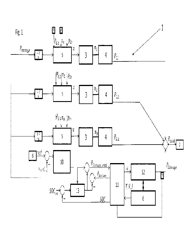
An embodiment of the invention is shown in Figs. 1 and 2.
Fig. 1 shows an exemplary power system according to the invention with several
prime
movers according to the invention which is at least temporarily controlled by
a method
according to the invention.
Fig. 2 shows a comparison between transient behavior of the power system
according
to Fig. 1 (solid lines) and a power system according to the prior art (broken
lines).
In the power system 1 of Fig. 1 a number N of gensets, each consisting of a
prime
mover 3 mechanically coupled by an output shaft to a generator 4 is shown.
Each prime
zo mover 3 provides mechanical drive force (and thus mechanical power) to
its generator 4
and is has a speed ni which can be measured by a second measuring device 8
(shown
only for the first prime mover 3). As a result of the mechanical coupling,
each generator
4 generates an electrical power PG,1 which is transmitted by a power grid.
Together the
generators 4 produce a sum of electrical powers ZPG,i. There can be a third
measuring
device 9 to provide a signal representing the amount of electrical power PG,,
generated
by the generator 4 to the control device 5 (only shown for the first prime
mover 3). Of
course, internal measurement values of the prime mover 3 can be provided to
the
control device 5 as is shown exemplary by the value p2s (load pressure).
An external load 2 couples to the power grid and has a momentary load
requirement
PLoad=
CA 03161265 2022- 6-8
WO 2021/146760
PCT/AT2020/060022
12
An energy storage device 6 in the form of an accumulator provided with power
electronics 12 and a storage control device 11 is also coupled to the power
grid. The
storage control device 11 receives temperature T, current magnitude I and
internal
voltage V of the energy storage device 6 and sends control commands u to the
power
electronics 12 to command exchange of power Pstorage (which can be negative or
positive; equivalent values like current can be controlled optionally) with
the power grid.
A computer 10 which in this embodiment together with a SOC control logic 13
forms a
master control device receives a speed n (selected from all the speeds n or
computed
from them, e. g. as an average value) and/or a frequency f of the power grid
and
compares them with reference values nõf and/or fõf. If there is a difference
between
momentary values n and/or f and reference values nõf and/or free the computer
10
concludes that a transient behavior of the power system 1 is present and sends
a
command value Pstorage,otod for power to be provided to or received from (i.
e. exchanged
with) the power grid to the storage control device 11. The magnitude of P
= Storage,cmd can
be for example proportional to the absolute speed error and its derivative (PD
controller). The amount of power Pstorage provided by energy storage device 6
is
measured by a first measuring device 7 and provided via storage control device
11 to
the control devices 5 of the prime movers 3 (this signal could also be
directly provided
zo to the control devices 5). In this example, only the portion of
electrical power which is
provided by the energy storage device 6 to the power grid that is used for
transient
regulation is provided to the control devices 5 by subtracting the command for
state of
charge control (output of SOC control logic 13). In this example, each control
device 5
knows that there is a number N of (in this case identical) prime movers 3
present and
can therefore divide the amount of power Pstorage provided by the energy
storage device
6 by the number N to determine what amount of electrical power Pai has to be
generated by the generator 4 coupled to its prime mover 3 to meet a power
requirement
Pload of the external load 2 (it has to add/subtract enough mechanical power
to come up
for the share Pstorage/A1 which, at the moment, is provided for or received by
the energy
storage device 6). In response to this, each control device 5 sends one or
several feed
forward command(s) u to actuators of its prime mover 3 to achieve this change
by
changing speed Ili of the prime mover 3.
CA 03161265 2022- 6-8
WO 2021/146760
PCT/AT2020/060022
13
The SOC control logic 13 can be PI or PID and receives the difference between
the
(externally or internally provided) state of charge set value SOCset and the
feedback
value of the state of charge SOC (output of storage control device 11) as an
input.
Optionally it can be disabled during transients by the output of computer 10.
The sum of the outputs of SOC control logic 13 and the computer 10 are used to
calculate Pstorage,cmd which is the commanded power to the storage control
device 11..
Fig. 2 shows in solid lines A an exemplary transient behavior of the power
system 1 of
Fig. 1.
Between time 0.1 and 0.2 load requirement PLoad of external load 2 suddenly
increases
which is shown by a sudden small drop in speed n from about 1 to about 0.995.
In
response to this, power Ps provided by the electric storage device 6 to the
external load
2 increases from about 0 to a little above 0.2. According to the invention,
after a short
sub-transient effect, power PG provided by all the generators 4 together
increases from
time 0.2 to about 0.4 such that power Ps provided by the electric storage
device 6 to the
external load 2 decreases to about 0. At the same time the speed approaches a
steady
state and therefore the power produced by the generators is equal to the
applied
external load.
The broken lines B show that without the invention, this state is still not
achieved by
time 0.55 but the long power consumption from the storage device 6 leads to an
emptying of energy storage device 6 and a pronounced drop in speed n between
time
0.55 and 0.8 until power provided by the prime movers 3 to the generators 4
can
compensate for the increased load requirement P
= Load of external load 2. This represents
a worst-case scenario, but even if it the storage does not become suddenly
empty, the
speed deviation from its reference is present for an undesired long duration.
CA 03161265 2022- 6-8
WO 2021/146760
PCT/AT2020/060022
14
List of reference numbers:
1 power system
2 external load
3 prime mover
4 generator
5 control device
6 energy storage device
7 first measuring device
8 second measuring device
9 third measuring device
10 computer
11 storage control device
12 power electronics
13 SOC control logic
number of prime movers
speed of prime mover
ni speed of ith prime mover
nõf reference value for speed
nõfj reference value for speed of prime mover
frequency of power grid
fret reference value for frequency of power grid
PLoad power requirement of external load
PG,i power generated by =th generator
PStorage power provided by energy storage device
PStorage,cmd command value for power provided by energy storage
device
control command
SOC state of charge of energy storage device
CA 03161265 2022- 6-8
WO 2021/146760
PCT/AT2020/060022
T temperature of energy storage device
V internal voltage of energy storage device
1 current magnitude delivered by/to energy storage device
CA 03161265 2022- 6-8