Note: Descriptions are shown in the official language in which they were submitted.
TRANSPORTATION TOOLING STRUCTURE, SPLIT ELECTRIC MOTOR
MODULE WITH TRANSPORTATION TOOLING STRUCTURE, AND
TRANSPORTATION METHOD
FIELD
[0001] The present application relates to the technical field of motors, and
in particular to a
transportation tooling structure, a split electric motor module with the
transportation tooling
structure and a transportation method.
BACKGROUND
[0002] A generator with a relatively large size is generally arranged in a
wind turbine to
convert mechanical energy into electrical energy. Especially for a direct-
drive wind turbine, a
diameter of the generator can reach more than ten meters. With the development
of the large
megawatt wind turbine, the size of the generator also needs to be increased
accordingly.
[0003] That the diameter of the generator of the large megawatt wind turbine
is too large
may cause trouble in transportation or assembly. At present, it is considered
to design the
generator as multiple independent generator units, transport the independent
generator units
separately, and then splice the multiple generator units into a complete
generator through
hoisting after a construction site is arrived. In this way, the simultaneous
cooperation of
multiple cranes and personnel is required, which is time-consuming and
laborious.
[0004] At present, a modular generator is designed to solve the transportation
problem of the
generator with the large diameter. Since the generator needs to be mounted on
site and the
assembly of a stator and a rotor on site is difficult, the site is much easier
if the stator and the
rotor of the generator can be transported at their original assembly
positions.
[0005] A generator in the conventional technology includes a stator with
multiple stator
segments and a rotor with multiple rotor segments, and at least one of the
stator segments and
at least one of the rotor segments can temporarily abut against for overall
transportation and
mounting. However, the structure of the motor, especially the structure for
temporary
abutment, is complex and difficult to manufacture.
CA 03161942 2022- 6- 14 - 1 -
SUMMARY
[0006] In one aspect, a transportation tooling structure of a split motor
module is provided
according to an embodiment of the present application, the split motor module
includes a split
rotor and a split stator which are arranged according to a preset assembly
requirement, the
transportation tooling structure include a split base plate, and the split
base plate is
correspondingly provided with at least one stator support and at least one
rotor support;
a lower end of the stator support is fixedly supported on an upper surface of
the split base
plate, and an upper end of the stator support is fixedly supported on a side,
close to the split
base plate, of the split stator; and
an upper end of the rotor support is fixedly supported on a side of an end,
close to the
split stator, of the split rotor, and a lower end of the rotor support is
fixedly supported on a
side, away from the split base plate, of the split stator.
[0007] In a second aspect, a split motor module with a transportation tooling
structure is
provided according to an embodiment of the present application, which includes
a split rotor
and a split stator which are arranged according to a preset assembly
requirement, and the
transportation tooling structure according to the first aspect;
the upper end of the stator support is fixedly supported on the side, close to
the split base
plate, of the split stator; and
the upper end of the rotor support is fixedly supported on the side of the
end, close to the
split stator, of the split rotor, and the lower end of the rotor support is
fixedly supported on the
side, away from the split base plate, of the split stator.
[0008] In a third aspect, a transportation method for a modular motor is
provided according
to an embodiment of the present application, which includes: arranging an
assembled modular
motor upside down on an upper surface of a base plate, so that multiple split
motor modules
are in one-to-one correspondence with multiple split base plates of the base
plate;
inserting two ends of a stator support respectively in a base plate side
stator support base
and a corresponding stator-side stator support base respectively, inserting
two ends of a rotor
support in a stator-side rotor support base and a corresponding rotor-side
rotor support base;
splitting a parting surface at a connection of each split rotor, a parting
surface at a
connection of each split stator, and a connecting member between the split
base plates; and
CA 03161942 2022- 6- 14 - 2 -
transporting the split motor module with a transportation tooling structure
separately
after a shafting is disassembled.
[0009] The technical solutions provided according to the embodiments of the
present
application have at least the following beneficial effects:
in the transportation tooling structure of the split motor module provided
according to the
embodiments of the present application, the stator support with a fixed
support function
between the split stator and the split base plate, and the rotor support with
a fixed support
function between the split stator and the end of the split rotor are provided,
so that the whole
split motor module can be transported with the split base plate on the premise
of maintaining
the preset assembly position of the split stator and the split rotor, which
solves the problem of
difficult overall transportation of the large-diameter modular motor, and the
transportation
tooling structure is simple and is easy to manufacture and mount.
[0010] The additional aspects and advantages of the present application will
be further
described in the following description, which will become apparent from the
following
description or be understood through the embodiments of the present
application.
BRIEF DESCRIPTION OF THE DRAWINGS
[0011] The above and/or additional aspects and advantages of the present
application will
become apparent and easy to understand with reference to the following
description of
embodiments in conjunction with the drawings.
[0012] FIG. 1 is a schematic structural view of a split motor module
(including a shafting)
with a transportation tooling structure provided according to an embodiment of
the present
application;
[0013] FIG. 2 is a schematic structural view of a modular motor with the
transportation
tooling structure provided according to the embodiment of the present
application;
[0014] FIG. 3 is a schematic top view of a split structure of a base plate
with the
transportation tooling structure provided according to the embodiment of the
present
application;
[0015] FIG. 4 is a front view of a split base plate with the transportation
tooling structure
provided according to the embodiment of the present application;
CA 03161942 2022- 6- 14 - 3 -
_
[0016] FIG. 5 is a schematic structural view of a first rigid reinforcement
tooling structure of
the transportation tooling structure provided according to the embodiment of
the present
application;
[0017] FIG. 6 is a schematic structural view of a second rigid reinforcement
tooling
structure of the transportation tooling structure provided according to the
embodiment of the
present application;
[0018] FIG. 7 is a schematic structural view of a third rigid reinforcement
tooling structure
of the transportation tooling structure provided according to the embodiment
of the present
application;
[0019] FIG. 8 is a schematic top view of a split structure of a rotor of the
modular motor
provided according to the embodiment of the present application;
[0020] FIG. 9 is a schematic axial cross-sectional view of a split rotor of
the modular motor
provided according to the embodiment of the present application;
[0021] FIG. 10 is a schematic structural view of a connection between adjacent
split rotors
of the modular motor provided according to the embodiment of the present
application;
[0022] FIG. 11 is a schematic top view of a split structure of a stator of the
modular motor
provided according to the embodiment of the present application;
[0023] FIG. 12 is a schematic view of a structure inside the split rotor of
the modular motor
provided according to the embodiment of the present application;
[0024] FIG. 13 is a schematic top view of a split structure of a rotor end
plate of the
transportation tooling structure provided according to the embodiment of the
present
application;
[0025] FIG. 14 is a front view of a split rotor end plate of the
transportation tooling structure
provided according to the embodiment of the present application; and
[0026] FIG. 15 is a flowchart of a split transportation method for the modular
motor
provided according to the embodiment of the present application.
[0027] The reference numerals are as follows:
1-rigid reinforcement tooling;
CA 03161942 2022- 6- 14 - 4 -
11-first rigid reinforcement tooling structure;
111-first reinforcement fixing seat;
12-second rigid reinforcement tooling structure;
121-second reinforcement fixing seat;
13-third rigid reinforcement tooling structure;
131-mounting hole;
2-rotor;
21-split rotor; 211-first flange fixing seat;
212-fixing seat hole; 213-rotor-side rotor support
base;
214-first side flange; 215-side flange hole; 216-
reinforcement rib;
217-reinforcement rib hole; 218-second side flange;
219-second flange fixing seat;
3-rotor support;
4-stator;
41-split rotor; 411-first side fixing plate;
412-first stator fixing hole; 413- stator-side stator
support base;
414-second side fixing plate; 415-second stator fixing
hole;
416-stator-side rotor support base; 417-iron core;
418-winding;
5- stator support;
6-shafting;
7-rotor end plate; 71-split rotor end plate;
710-parting surface; 711-fixing side plate;
712-end plate fixing hole;
8- base plate; 81-split base plate;
CA 03161942 2022- 6- 14 - 5 -
811-base plate side stator support base.
DETAILED DESCRIPTION OF EMBODIMENTS
[0028] The embodiments of the present application are described in detail
hereinafter, and
are illustrated in drawings, in which the same or similar reference signs
represent the same or
similar elements or elements with the same or similar functions throughout the
description. In
addition, if a detailed description of the known technology is unnecessary for
the illustrated
features of the present application, it will be omitted. The embodiments
described in the
following with reference to the drawings are only exemplary embodiments which
are used to
explain the present application, and should not be construed to limit the
present application.
[0029] It should be understood by those skilled in the art that all terms
(including technical
and scientific terms) used herein have the same meaning as commonly understood
by one of
ordinary skilled in the art to which the present application belongs, unless
otherwise defined.
It should also be understood that terms such as those defined in a general
dictionary have the
same meaning as that in the context of the prior art unless specifically
defined, and should not
be interpreted in an idealized or overly formal sense.
[0030] Those skilled in the art should understand that, unless explicitly
stated, the singular
forms used herein such as "a", "an", "one", and "this one" are intended to
include the plural
forms. It should be further understood that, the terms "include/comprise",
when used in the
description, indicate the existence of a feature, an integer, a step, an
operations, an element
and/or a component, but does not exclude the existence or addition of one or
more of other
features, integers, steps, elements, components and/or combinations thereof.
It should be
understood that the term "and/or" used herein includes all or any unit or all
combinations of
one or more associated listed items.
[0031] A motor includes a stator and a rotor, and the rotor of the motor with
different
diameters can be selected according to the different power levels of the
motor. In order to
facilitate the transportation of a generator with a large diameter, the
generator is generally
arranged as multiple independent split rotors and multiple independent split
stators. A single
split rotor corresponds to a single split stator to form a single split motor
module according to
a preset assembly requirement. Each split motor module is transported
separately. After the
transportation process is completed, the multiple split motor modules are
assembled to form
CA 03161942 2022- 6- 14 - 6 -
the complete rotor and the complete stator, and then the assembly of the motor
is completed
based on the complete rotor and the complete stator.
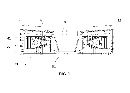
[0032] FIG. 1 is a schematic structural view of a split motor module with a
transportation
tooling structure provided according to an embodiment of the present
application; and FIG. 2
is a schematic structural view of a modular motor after the transportation
tooling structure is
mounted according to an embodiment of the present application. In order to
facilitate
understanding, the following is a clear and detailed description of the
transportation tooling
structure of the split motor module according to the embodiment of the present
application in
combination with FIG. 1 and FIG. 2. The split motor module includes a split
rotor 21 and a
split stator 41 which are arranged according to a preset assembly requirement.
The
transportation tooling structure includes a split base plate 81, and the split
base plate 81 is
correspondingly provided with at least one stator support 5 and at least one
rotor support 3.
[0033] A lower end of the stator support 5 is fixedly supported on an upper
surface of the
split base plate 81, and an upper end of the stator support 5 is fixedly
supported on a side,
close to the split base plate 81, of the split stator 41; an upper end of the
rotor support 3 is
fixedly supported on a side of an end, close to the split stator 41, of the
split rotor 21, and a
lower end of the rotor support 3 is fixedly supported on a side, away from the
split base plate
81, of the split stator 41.
[0034] In the transportation tooling structure of the split motor module
provided according
to the embodiments of the present application, the stator support 5 with a
fixed support
function between the split stator 41 and the split base plate 81 and the rotor
support 4 with a
fixed support function between the split stator 41 and the end of the split
rotor 21 are provided,
so that the whole split motor module can be transported with the split base
plate 81 on the
premise of maintaining the preset assembly position of the split stator 41 and
the split rotor 21,
which solves the problem of difficult overall transportation of the large-
diameter modular
motor, and the transportation tooling structure is simple and is easy to
manufacture and
mount.
[0035] Specifically, as shown in FIG 8 and FIG. 11, a single split motor
module can be
regarded as a part of the whole modular motor after splitting, which includes
a split rotor 21
and a split stator 41. The split rotor 21 and the split stator 41 are arranged
correspondingly
and arranged according to the preset assembly requirement (for example,
maintaining an
CA 03161942 2022- 6- 14 - 7 -
original air gap), so as to facilitate rapid mounting after transportation. In
order to keep the
preset assembly position of the split rotor 21 and the split stator 41
unchanged during
transportation, as shown in FIG. 3 and FIG. 4, in this embodiment, the split
base plate 81 is
used as a base of the whole split motor, and a single split base plate 81 can
be regarded as a
part of a base plate 8 after being split along a radial direction. A diameter
of the base plate 8
should be slightly larger than a diameter of the whole modular motor, a size
of the split base
plate 8 is adaptively adjusted according to a size of the split motor module,
and the split base
plates 8 can be detachably connected to form the base plate 8.
[0036] The number of the stator supports 5 and the rotor supports 3 on the
split base plate 81
can be provided according to the actual demand, as long as it can meet the
fixed support of the
split stator 41 and the split rotor 21. The specific number here may not be
limited. The stator
support 5 and the rotor support 3 can be rigid pipes or rods, and cross
sections of the stator
support 5 and the rotor support 3 can be rectangular, circular or annular. In
order to enhance
the effect of fixed support, the cross sections of the stator support 5 and
the rotor support 3
can be appropriately increased.
[0037] In a case that the split base plate 81 is placed horizontally, the
split motor module is
located directly above the split base plate 81, the lower end of the stator
support 5 is fixedly
supported on the upper surface of the split base plate 81, and the upper end
of the stator
support 5 is fixedly supported on the side, close to the split base plate 81,
of the split stator 41.
The specific fixed support method of the stator support 5 may be a fixed
connection through
the fastening of a connecting member, or an inserting connection of the stator
support 5
passing through the upper surface of the split base plate 81 and the mounting
seat reserved on
the side, close to the split base plate 81, of the split stator 41.
Alternatively, in order to
strengthen the fixing effect, the split stator 41 can also be fixedly
supported through the
combination of the inserting connection of the mounting seat and the fastening
of the
connecting member.
[0038] Similarly, the upper end of the rotor support 3 is fixedly supported at
the end of the
split rotor 21, and the upper end of the rotor support 3 is specifically
fixedly supported at the
side, close to the split stator 41, of the end of the split rotor 21 according
to the preset
assembly requirement of the split rotor 21 and the split stator 41; and the
lower end of the
rotor support 3 is fixedly supported on the side, away from the split base
plate 81, of the split
CA 03161942 2022- 6- 14 - 8 -
stator 41. The specific fixed support method of the rotor support 3 may be a
fixed connection
through the fastening of the connecting member, or an inserting connection of
the rotor
support 3 passing through the end of the split rotor 21 and the mounting seat
reserved on the
side, away from the split base plate 81, of the split stator 41.
Alternatively, in order to
strengthen the fixing effect, the split stator 41 can also be fixedly
supported through the
combination of the inserting connection of the mounting seat and the fastening
of the
connecting member.
[0039] It should be noted that the rotor of the motor can be regarded as a
cylindrical
structure with an open end, the end of the split rotor 21 is an end of the
rotor. Since the open
end of the rotor faces the base plate 8, the end of the split rotor 21 is
regarded as an end, away
from the split base plate 81, of the split rotor 21.
[0040] According to an embodiment of the present application, referring to
FIG. 1,
optionally, an extending direction of the stator support 5 and an extending
direction of the
rotor support 3 are perpendicular to the split base plate 81.
[0041] In this embodiment, the extending direction of the stator support 5 and
the extending
direction of the rotor support 3 are perpendicular to the split base plate 81,
which is equivalent
to the situation that the stator support 5 and the rotor support 3 are
arranged in a vertical
direction for the split base plate 81 which is placed horizontally, so as to
improve the support
strength of the split stator 41 and the split rotor 21, and be beneficial to
maintaining the
support stability of the whole split motor module.
[0042] According to the embodiment of the present application, further
referring to FIG. 1
and FIG. 3, optionally, multiple stator supports 5 and multiple rotor supports
3 are provided.
The multiple stator supports 5 are arranged in an arc array on the upper
surface of the split
base plate 81, and projection of the multiple rotor supports 3 on the upper
surface of the split
base plate 81 are arranged in an arc array.
[0043] In this embodiment, the multiple stator supports 5 and the multiple
rotor supports 3
are provided, the multiple stator supports 5 are arranged in the arc array on
the upper surface
of the split base plate 81, and the projection of the multiple rotor supports
3 on the upper
surface of the split base plate 81 are arranged in the arc array, which can
further improve the
support strength and stability of the split stators 41 and the split rotors
21. The number of the
plurality of stator supports 5 and the plurality of rotor supports 3 may be
the same or different,
CA 03161942 2022- 6- 14 - 9 -
and may be selectively provided according to the specific size and structure
of the split rotor
21 and the split stator 41.
[0044] Specifically, since the split rotor 21 and the split stator 41 have a
substantial
semicircle or a fan-shaped structure, the multiple stator supports 5 are
arranged in the arc
array on the upper surface of the split base plate 81, and the arc formed by
projections of the
multiple stator supports 5 on the split base plate 81 has a same center as the
base plate 8
corresponding to the split base plate 81, so as to allow the suffering force
of each stator
support 5 and each rotor support 3 to be uniform, and improve the support
strength of the split
stator 41 and the split rotor 21. In order to allow the suffering force of the
rotor support 3 to
be uniform, the projections of the multiple rotor supports 3 on the upper
surface of the split
base plate 81 are also arranged in the arc array. It should be noted that the
arc formed by the
projection of the multiple rotor supports 3 on the upper surface of the split
base plate 81 and
the arc formed by the projection of the multiple stator supports 5 on the
split base plate 81 can
have the same radius or different radii, which can be set according to actual
needs.
[0045] According to an embodiment of the present application, as shown in FIG.
3 and FIG.
4, a base plate side stator support base 811 with an opening facing the split
stator 41 is
provided on the upper surface of the split base plate 81, each base plate side
stator support
base 811 is in one-to-one correspondence with each stator support 5, and a
lower end of each
stator support 5 is inserted in the corresponding base plate side stator
support base 811.
[0046] In this embodiment, it is convenient for the lower end of the stator
support 5 and the
split base plate 81 to be fixedly supported by inserting through arranging the
base plate side
stator support base 811 on the upper surface of the split base plate 81, which
can improve the
mounting efficiency of the transportation tooling structure.
[0047] Specifically, the base plate side stator support base 811 is a mounting
seat which
extends upward from the upper surface of the split base plate 81. The mounting
seat has a
cylindrical structure with an open upper end, and an interior of the
cylindrical structure is
matched with the lower end of the split stator 41, and a matching gap can be
properly reserved.
Certainly, corresponding multiple base plate side stator support bases 811 are
provided in the
case of the multiple supporting stators 5, and the multiple base plate side
stator support bases
811 can also be arranged according to the arc array, so that the multiple
stator supports 5 are
arranged in the arc array on the upper surface of the split base plate 81,
which improves the
CA 03161942 2022- 6- 14 - 10 -
support strength and stability of the split motor module.
[0048] Alternatively, in order to improve the connection strength between the
stator support
and the split base plate 81, a mounting hole is defined in the base plate side
stator support
base 811 in a direction perpendicular to the stator support 41, and a
connecting hole
corresponding to the mounting hole in position is defined in the lower end of
the stator
support 5, so that the lower end, inserted in the base plate side stator
support base 811, of the
stator support 5 can be fixed (for example, through a bolt fastener).
[0049] According to an embodiment of the application, as shown in Fig. 2 and
FIG. 10, in
order to enhance the rigidity of a parting surface of the split rotor 21, the
transportation
tooling structure in this embodiment includes a rigid reinforcement tooling 1
for enhancing
the rigidity of the split rotor 21 in addition to the split base plate 81, the
stator support 5 and
the rotor support 3 in the above embodiments. The rigid reinforcement tooling
1 includes a
first rigid reinforcement tooling structure 11 and a second rigid
reinforcement tooling
structure 12, the first rigid reinforcement tooling structure 11 is detachably
connected with a
side flange at one parting surface of the split rotor 21, and the second rigid
reinforcement
tooling structure 12 is detachably connected with a side flange at another
parting surface of
the split rotor 21.
[0050] The first rigid reinforcement tooling structure 11 and the second rigid
reinforcement
tooling structure 12 are formed by butting ends of two first plate-shaped
structures with an
extending direction in a right angle or a substantially right angle; or the
first rigid
reinforcement tooling structure 11 and the second rigid reinforcement tooling
structure 12 are
both of a first plate-shaped structure with an extending direction in a right
angle or a
substantially right angle; and cross sections of the first plate-shaped
structures are L-shaped.
[0051] In this embodiment, the parting surface of the split rotor 21 is a
connecting surface of
the split rotor 21when the split rotor 21 is assembled with the adjacent split
rotor 21. The
rigidity at the parting surfaces of the split rotor 21 is enhanced by mounting
the first rigid
reinforcement tooling structure 11 and the second rigid reinforcement tooling
structure 12
which are matched the parting surfaces at the two parting surfaces of the
split rotor 21
respectively, which can prevent the rotor from deforming due to weak rigidity
or being
damaged by absorption of the split stator 41 after the rotor is split into the
split rotors 21.
[0052] Specifically, as shown in FIG. 5 and FIG. 6, an overall shape of the
first rigid
CA 03161942 2022- 6- 14 - 11 -
reinforcement tooling structure 11 and the second rigid reinforcement tooling
structure 12 is
similar to the L-shape, which is related to the shape of an axial cross
section of the split rotor
21 in FIG. 9. This structural design can be matched with the shape of each
parting surface of
the split rotor 21. The first rigid reinforcement tooling structure 11 and the
second rigid
reinforcement tooling structure 12 can form an overall L-shaped tooling
structure by ends of
two separate first plate-shaped structures with an extending direction at a
right angle or a
substantially right angle by means of welding, inserting or bolt connection.
The first rigid
reinforcement tooling structure 11 and the second rigid reinforcement tooling
structure 12
may be of the first plate-shaped structure with the extension direction in the
right angle or the
substantially right angle (equivalent to an L-shape as a whole), and the first
plate-shaped
structure can be integrally formed by a corresponding mold.
[0053] In this embodiment, the side flanges at the two parting surfaces of the
split rotor 21
can be defined as a first side flange 214 and a second side flange 218
respectively. The first
rigid reinforcement tooling structure 11 is connected with the first side
flange 214, and the
second rigid reinforcement tooling structure 12 is connected with the second
side flange 218.
In order to facilitate mounting and disassembly, both the first rigid
reinforcement tooling
structure 11 and the second rigid reinforcement tooling structure 12 are
detachably mounted,
such as clamp or bolt connection.
[0054] In order to facilitate the mounting of the parting surface of the
adjacent split rotor 21,
the first rigid reinforcement tooling structure 11 is mounted on a side, away
from the parting
surface, of the first side flange, and the second rigid reinforcement tooling
structure 12 is
mounted on a side, away from the parting surface, of the second side flange
218. Since the
cross sections of the first plate-shaped structures for forming the first
rigid reinforcement
tooling structure 11 and the second rigid reinforcement tooling structure 12
are L-shaped, the
first rigid reinforcement tooling structure 11 and the second rigid
reinforcement tooling
structure 12 on the side flanges at the parting surfaces of the adjacent split
rotors 21 can be
mounted "back-to-back", which can avoid interference during the mounting of
the
reinforcement tooling. The ends of the two first plate-shaped structures can
be fixedly
connected by means of screws, riveting, welding or integrated forming.
[0055] Based on the above embodiments, as shown in FIG. 2, FIG. 7 and FIG. 9,
in addition
to the first rigid reinforcement tooling structure 11 and the second rigid
reinforcement tooling
CA 03161942 2022- 6- 14 - 12 -
structure 12 at the parting surfaces, the rigid reinforcement tooling 1
further includes a third
rigid reinforcement tooling structure 13 for being detachably connected with a
reinforcement
rib 216 on an outer side surface of the split rotor 21.
[0056] The third rigid reinforcement tooling structure 13 is formed by butting
ends of two
second plate-like structures with an extending direction in a right angle or a
substantially right
angle; or, the third rigid reinforcement tooling structure 13 is of the second
plate-shaped
structure with the extending direction at the right angle or the substantially
right angle; and a
cross section of the second plate-shaped structure is T-shaped or L-shaped.
[0057] In this embodiment, the rigidity between the two parting surfaces of
the split rotor 21
can be enhanced by mounting the third rigid reinforcement tooling 13 on the
outer side
surface of the split rotor 21. In order to facilitate the mounting of the
third rigid reinforcement
tooling 13, the reinforcement rib 216 can be pre-provided on the outer side
surface of the split
rotor 21, and the reinforcement rib 216 can be welded, bolted or integrally
formed with the
split rotor 21. The reinforcement rib 216 is located between the first side
flange 214 and the
second side flange 218 of the same split rotor 21. The specific number and
spacing of the
reinforcement rib 216 can be appropriately adjusted according to the size of
the split rotor 21.
[0058] The third rigid reinforcement tooling structure 13 may be an overall L-
shaped tooling
structure formed by the ends of the two separate second plate-shaped
structures with an
extending direction in a right angle or a substantially right angle by means
of welding,
inserting or bolt connection. The third rigid reinforcement tooling structure
13 may be of the
second plate-shaped structure with the extension direction at the right angle
or the
substantially right angle (equivalent to an L-shape as a whole), and the first
plate-shaped
structure can be integrally formed by a corresponding mold.
[0059] Specifically, in order to improve the mounting efficiency of the third
rigid
reinforcement tooling structure 13, the third rigid reinforcement tooling
structure 13 is
detachably connected with the reinforcement rib 216, such as by clamping or
bolt connection.
Multiple reinforcement rib holes 217 can be defined in the reinforcement rib
216, and
mounting holes 131 corresponding to the reinforcement rib hole 217 in position
can be
defined in the third rigid reinforcement tooling structure 13. The
reinforcement rib holes 217
and the mounting holes 131 are fastened by bolts, so as to further improve the
rigidity of the
split rotor 21.
CA 03161942 2022- 6- 14 - 13 -
[0060] In addition, since the shape of the reinforcement rib 216 is matched
with the axial
cross section of the split rotor 21, the third rigid reinforcement tooling
structure 13 in this
embodiment is formed by butting the ends of two second plate-like structures
with the
extending direction in the right angle or the substantially right angle, so as
to form a structure
with an overall shape similar to the L-shape. The ends of the two second plate-
like structures
can also be fixedly connected by means of screws, riveting, welding or
integrated forming.
[0061] Alternatively, the cross section of the second plate-shaped structure
can be T-shaped
or L-shaped, which has a better rigidity than the cross section of an in-line
shape. In the case
that the cross section of the second plate-shaped structure is T-shaped, the
second
plate-shaped structure includes a transverse rib and a longitudinal rib which
is vertically
connected in the middle of the transverse rib. The mounting hole 131 can be
arranged in the
longitudinal rib, so as to realize the connection with the reinforcing rib
hole 217.
[0062] According to an embodiment of the application, as shown in FIG. 2, the
following
embodiments can be adopted to further enhance the rigidity of the split rotor
21 considering
the large deformation of the split rotor 21 that: in the first rigid
reinforcement tooling structure
11 and the second rigid reinforcement tooling structure 12, the first plate
structures located on
an outer circumference of the split rotor 21 are fixedly connected with the
upper surface of the
split base plate 81 respectively; in the third rigid reinforcement tooling
structure 13, the
second plate-shaped structure located on the outer circumferential surface of
the split rotor 21
is fixedly connected with the upper surface of the split base plate 81.
[0063] In this embodiment, ends, close to the split base plate 81, of the
first rigid
reinforcement tooling structure 11, the second rigid reinforcement tooling
structure 12 and the
third rigid reinforcement tooling structure 13 are fixedly connected with the
split base plate 81,
so as to further enhance the rigidity of the split rotor, which can also
disperse the support
forces of the support stator 5 and the support rotor 7, and improve the
support stability of the
whole transportation tooling structure on the split motor module.
[0064] Specifically, since the first rigid reinforcement tooling structure 11,
the second rigid
reinforcement tooling structure 12 and the third rigid reinforcement tooling
structure 13 are all
regarded as structures with an overall shape similar to L-shape, the
horizontal section in the
L-shaped structure is connected with an outer side surface of the end of the
split rotor 21, and
the vertical section in the L-shaped structure is connected with the outer
circumferential
CA 03161942 2022- 6- 14 - 14 -
surface of the split rotor 21, and lower ends of the vertical sections in the
L-shaped structures
can all be connected with the upper surface, close to an outer edge, of the
split base plate 81,
so as to strengthen the support of the whole split rotor 21.
[0065] The lower end of the vertical section in each L-shaped structure can be
connected
with the upper surface of the split base plate 81 by riveting or bolt
connection. Alternatively,
in order to facilitate the connection, a corresponding connection base can
further be arranged
on the upper surface, close to the outer edge, the split base plate 81, so as
to realize the
connection with the first rigid reinforcement tooling structure 11, the second
rigid
reinforcement tooling structure 12 and the third rigid reinforcement tooling
structure 13 by the
connection base.
[0066] According to an embodiment of the present application, as shown in FIG.
13 and FIG.
14, in order to enhance the rigidity along a circumferential direction of the
split rotor, the
transportation tooling structure provided according to the embodiment further
includes a split
rotor end plate 71. The split rotor end plate 71 is arranged in parallel above
the split base plate
81, and an outer edge of the split rotor end plate 71 is detachably connected
with an inner
circumferential surface of an open end of the split rotor 21.
[0067] The split rotor end plate 71 has a partial annular structure; or, a
hollow portion for the
stator support 5 to pass through is reserved on the split rotor end plate 71.
[0068] In this embodiment, the split rotor end plate 71 is arranged on the
inner
circumferential surface of the open end of the split rotor 21, and the split
rotor is supported by
the split rotor end plate 71, so as to improve the rigidity along the
circumferential direction of
the split rotor 21, prevent the split rotor 21 from deforming or being damaged
caused by the
adsorption of the split stator 41, and facilitate the split transportation
according to the preset
assembly requirement.
[0069] Specifically, in this embodiment, the split rotor end plate 71 can be
regarded as a part
of the rotor end plate 7 after being split along a radial direction. A
diameter of the rotor end
plate 7 is matched with an inner diameter of the split rotor 21, and the rotor
end plate 7 can be
formed by detachable connection of the split rotor end plates 71. The whole
rotor end plate 7
can be connected with the inner circumference of the rotor 2 as a whole before
split
transportation, as long as the split rotor end plates 71 can be connected with
the split rotors 21
in one-to-one correspondence. The split rotor end plate 71 is detachably
connected with the
CA 03161942 2022- 6- 14 - 15 -
inner circumferential surface of the open end of the corresponding split rotor
21, so that the
disassembly can be realized after the modular motor is assembled.
[0070] It should be noted that the open end of the split rotor 21 is an open
end of the rotor 2.
The open end of the rotor 2 is located at an end, away from the rotor 2, of
the rotor 2. The
open end of the split rotor 21 is close to the split base plate 81 when the
split rotor 21 is
arranged on the split base plate 81, so that an outer edge of the split rotor
end plate 71 is
located above the split base plate 81 when the outer edge of the split rotor
end plate 71 is
connected with the inner circumferential surface of the split rotor 21.
[0071] In addition, considering that the stator support 5 is arranged between
the split stator
41 and the split base plate 81, the whole rotor end plate 7 can be arranged as
an annular
structure with a space for mounting the stator support 5 reserved in the
middle, that is, the
split rotor end plate 71 is of a partial annular structure, so as to avoid
interference between the
stator support 5 and the split rotor 71. Alternatively, a hollow portion for
the stator support 5
to pass through can be reserved on the split rotor end plate 71, and a size
and position of the
hollow portion can be set according to the position for fixed support on the
rotor 2.
[0072] Based on the same inventive concept, as shown in FIG. 1 and FIG. 2, a
split motor
module with a transportation tooling structure is provided according to the
embodiment of the
present application, which includes: a split rotor 21 and a split stator 41
which are arranged
according to a preset assembly requirement, and the transportation tooling
structure in the
above embodiments; the lower end of the stator support 5 is fixed on the upper
surface of the
split base plate 81, and the upper end of the stator support 5 is fixed on the
side, close to the
split base plate 81, of the split stator 41; the upper end of the rotor
support 3 is fixedly
supported on the side, close to the split stator 41, of the end of the split
rotor 21, and the lower
end of the rotor support 3 is fixedly supported on the side, away from the
split base plate 81,
of the split stator 41.
[0073] In this embodiment, for how the stator support 5 and the rotor support
3 realize the
fixed support for the split stator 41 and the split rotor 21 in the split
motor module, reference
can be made to the content of the transportation tooling structure in the
above embodiments,
which will not be described in detail here.
[0074] In the split motor module with the transportation tooling structure
provided in this
embodiment, the stator support 5 with a fixed support function between the
split stator 41 and
CA 03161942 2022- 6- 14 - 16 -
the split base plate 81, and the rotor support 4 with a fixed support function
between the split
stator 41 and the end of the split rotor 21 are provided, so that the whole
split motor module
can be transported with the split base plate 81 on the premise of maintaining
the preset
assembly position of the split stator 41 and the split rotor 21, which solves
the problem of
difficult overall transportation of the large-diameter modular motor, and the
transportation
tooling structure is simple and is easy to manufacture and assembly.
[0075] According to an embodiment of the present application, two parting
surfaces of the
split rotor 21 are respectively provided with a first side flange 214 and a
second side flange
218, the first rigid reinforcement tooling structure 11 is detachably
connected with the first
side flange 214, and the second rigid reinforcement tooling structure 12 is
detachably
connected with the second side flange 218.
[0076] In this embodiment, the set position of the first side flange 214 and
the second side
flange 218 and the connection mode of the first rigid reinforcement tooling 11
and the second
rigid reinforcement tooling 12 can make reference to the content of the
transportation tooling
structure in the above embodiments, which will not be described in detail
here.
[0077] In the split motor module with the transportation tooling structure in
this embodiment,
the parting surface of the split rotor 21 is a connecting surface of the split
rotor 21 when the
split rotor 21 is assembled with the adjacent split rotor 21. The rigidity at
the parting surfaces
of the split rotor 21 is enhanced by mounting the first rigid reinforcement
tooling structure 11
and the second rigid reinforcement tooling structure 12 which are matched the
parting
surfaces at the two parting surfaces of the split rotor 21 respectively,
thereby preventing the
rotor from deforming due to weak rigidity or being damaged by absorption of
the split stator
41 after the rotor is split into the split rotors 21.
[0078] Based on the above embodiments, as shown in FIG. 2 and FIG. 9, multiple
first
flange fixing seats 211 extend from an edge of the first side flange 214 in a
direction away
from the split stator 41, and multiple second flange fixing seats 219 extend
from an edge of
the second side flange 218 in the direction away from the split stator 41; the
multiple first
flange fixing seats 211 and the multiple second flange fixing seats 219 are
asymmetric with
respect to a centerline of the split rotor 21; multiple first reinforcement
fixing seats 111 are
provided in the first rigid reinforcement tooling structure 11, and the
multiple first
reinforcement fixing seats 111 are detachably connected with the multiple
first flange fixing
CA 03161942 2022- 6- 14 - 17 -
seats 211; and multiple second reinforcement fixing seats 121 are provided in
the second rigid
reinforcement tooling structure 12, and the multiple second reinforcement
fixing seats 121 are
detachably connected with the multiple second flange fixing seats 219.
[0079] In this embodiment, by arranging the first flange fixing seats 211 and
the second
flange fixing seats 219 on the first side flange 214 and the second side
flange 218 which are
asymmetric with respect to the centerline of the split rotor 21, it is
possible to prevent the
rigid reinforcement tooling on the corresponding side flanges from interfering
and affecting
the mounting when the adjacent split rotors 21 are connected.
[0080] Specifically, a fixing seat hole 212 is respectively defined on the
first flange fixing
seats 211 and the second flange fixing seats 219, and mounting holes
corresponding to the
fixing seat hole 212 are respectively defined on the first reinforcement
fixing seats 111
correspondingly connected with the first flange fixing seats 211 and the
second reinforcement
fixing seats 121 correspondingly connected with the second flange fixing seats
219, and the
mounting hole is fixedly connected with the fixing seat hole 212 by a bolt
after alignment.
[0081] It should be noted that a side flange hole 215 is defined in both the
first side flange
214 and the second side flange 218, the adjacent split rotors 21 are aligned
and abut through
the first side flange 214 and the second side flange 218, and fixation can be
realized after the
bolts are mounted in the side flange holes 215, so as to form the complete
rotor 2.
[0082] According to an embodiment of the present application, as shown in FIG.
2 and FIG.
9, multiple reinforcement ribs 216 are provided on an outer surface of the
split rotor 21, and
each reinforcement rib 216 extends along an axial direction and a radial
direction of the split
rotor 21; and the third rigid reinforcement tooling structure 13 is detachably
connected with
the multiple the reinforcing ribs 216.
[0083] It should be noted that the outer surface of the split rotor 21
includes the outer
circumferential surface of the split rotor 21 and the outer surface of the end
of the split rotor
21, and each reinforcing rib 216 includes a portion which extends along the
axial direction on
the outer circumferential surface of the split rotor 21 and a portion which
extends along the
radial direction on the outer surface of the end of the split rotor 21, and
the two portions are of
a continuous integral structure.
[0084] In this embodiment, the reinforcement rib 216 can be welded, bolted or
integrally
CA 03161942 2022- 6- 14 - 18 -
formed with outer surface of the split rotor 21. The reinforcement rib 216 is
located between
the first side flange and the second side flange 218 of the same split rotor
21. The specific
number and spacing of the reinforcement ribs 216 can be appropriately adjusted
according to
the size of the split rotor 21. The specific connection mode of the third
rigid reinforcement
tooling 13 and the reinforcement ribs 216 can make reference to the content of
the
transportation tooling structure in the above embodiments, which will not be
described in
detail here. In the split motor module with the transportation tooling
structure provided in this
embodiment, the rigidity between the two parting surfaces of the split rotor
21 can be
enhanced by mounting the third rigid reinforcement tooling 13 at the
reinforcement ribs 216
on outer side surface of the split rotor 21.
[0085] According to an embodiment of the present application, as shown in FIG.
13 and FIG.
14, an outer edge of a split rotor end plate 71 is detachably connected with
an inner
circumferential surface of an open end of the split rotor 21; a fixing side
plate 711 for being
connected with the adjacent split rotor end plate 71 is arranged at a split
surface 710 of each
split rotor end plate 71, and an end plate fixing hole 712 is defined on the
fixing side plate
711.
[0086] In this embodiment, the specific mounting position and matching form of
the split
rotor end plate 71 and the split rotor 21 can make reference to the content of
the transportation
tooling structure in the above embodiments, which will not be described in
detail here.
[0087] In addition, in order to facilitate the connection between the split
rotor end plates 71
to form a complete rotor end plate 7, the fixing side plate 711 is provided at
the split surface
710 of each split rotor end plate 71, and the split surfaces 710 of adjacent
split rotor end plates
71 can be fixedly connected through the respective fixing side plates 711. The
end plate fixing
hole 712 is defined on each fixing side plate 711, and a connecting member can
be mounted in
the end plate fixing holes 712 of the adjacent split rotors 71, so as to
realize the detachable
connection of the adjacent split rotor end plates 71. It should be noted that
the split surface
710 of the split rotor end plate 71 refers to an interface after the whole
rotor end plate 7 is
split according to the size of the split rotor 21, and the complete rotor end
plate 7 can be
formed after the split surfaces 710 of the adjacent split rotor end plates 71
are connected. In
the split motor module with the transportation tooling structure provided in
this embodiment,
the split rotor end plate 71 is arranged on the inner circumferential surface
of the open end of
CA 03161942 2022- 6- 14 - 19 -
the split rotor 21, and the split rotor is supported by the split rotor end
plate 71, so as to
improve the rigidity along the circumferential direction of the split rotor
21, prevent the split
rotor 21 from deforming or being damaged caused by the adsorption of the split
stator 41, and
facilitate the split transportation according to the preset assembly
requirement.
[0088] According to an embodiment of the present application, as shown in FIG.
3, FIG. 11
and FIG. 12, stator-side stator support bases 413 with an opening facing the
split base plate 81
are provided on a lower portion of the split stator 41, and the stator-side
stator support bases
413 are in one-to-one correspondence with base plate side stator support bases
811;
stator-side rotor support bases 416 with an opening facing the end of the
split rotor 21
are provided on an upper portion of the split stator 41, rotor-side rotor
support bases 213 with
an opening facing the split stator 41 are provided on the side of the end,
close the split stator
41, of the split rotor 21, and the rotor-side rotor support bases 213 are in
one-to-one
correspondence with the stator-side rotor support bases 416; and
two ends of the stator support 5 are respectively inserted in the base plate
side stator
support base 811 and the corresponding stator-side stator support base 413,
and two ends of
the rotor support 3 are respectively inserted in the stator-side rotor support
base 416 and the
corresponding rotor-side rotor support base 213.
[0089] Each split stator 41 includes a first side fixing plate 411, a first
stator fixing hole 412,
a stator-side stator support base 413, a second side fixing plate 414, and a
second stator fixing
hole 415, a stator-side rotor support base 416, an iron core 417, and a
winding 418. The split
stators 41 can be connected with each other by a bolt through the first stator
fixing hole 412
and the second side fixing plate 414. The stator-side stator support base 413
and the
stator-side rotor support base 416 are distributed circumferentially along a
central axis of the
stator 4 and welded or riveted on the split stator 41. A circumferential
position of the
stator-side stator support base 413 needs to be consistent with a
circumferential position of the
base-side stator support 811, and a circumferential position of the stator-
side rotor support
base 416 is consistent with a circumferential position of the rotor-side rotor
support base 213.
The iron core 417 can be fixed on the split stator 41 by means of a bolt or
welding, and is
laminated according to the actual situation of the split stator 41. The
winding 418 is
embedded in the iron core 417.
[0090] In the split motor module with transportation tooling structure
provided in this
CA 03161942 2022- 6- 14 - 20 -
embodiment, bases for positioning and mounting the rotor support 3 and stator
support 5 are
provided on the upper surface of the split base plate 81, the upper portion
and the lower
portion of the split stator 41 and the end of the split rotor 21, so as to
facilitate the fixed
support of the rotor support 3 and stator support 5 through inserting, and
improve the
mounting efficiency of the transportation tooling structure, and the support
stability is high.
[0091] Based on the same inventive concept, as shown in FIG. 15, a split
transportation
method for the modular motor is provided according to the embodiment of the
present
application, which includes:
arranging an assembled modular motor upside down on an upper surface of a base
plate
8, so that each split motor module is in one-to-one correspondence with each
split base plate
81 of the base plate 8;
inserting two ends of a stator support 5 respectively in a base plate side
stator support
base 811 and a corresponding stator-side stator support base 413 respectively,
inserting two
ends of a rotor support 3 in a stator-side rotor support base 416 and a
corresponding rotor-side
rotor support base 213;
splitting a parting surface at a connection of each split rotor 21, a parting
surface at a
connection of each split stator 41, and a connecting member between the split
base plates 81;
and
transporting the split motor module with a transportation tooling structure
separately
after a shafting is disassembled.
[0092] In this embodiment, the assembled modular motor is mounted with the
transportation
tooling structure, and then the connecting members at the parting surface of
each split rotor
and each split stator in the modular motor and the connecting members between
split base
plate are removed, so that the split rotor and the split stator in each split
motor module can
maintain the original assembly requirement, the whole split motor module can
be transported
as a whole separately, the split motor module is assembled after the mounting
site is arrived,
and then the transportation tooling structure module is disassembled, which
solves the
problem of difficult overall transportation of the large-diameter modular
motor, and the
transportation tooling structure is simple and is easy to manufacture and
mount.
[0093] Based on the above embodiments, in order to improve the rigidity of the
split rotor
CA 03161942 2022- 6- 14 - 21 -
21, the method includes before step S3: mounting a first rigid reinforcement
tooling structure
11 on a first side flange 214 at the connection of each split rotor 21, and
mounting a second
rigid reinforcement tooling structure 12 on a second side flange 218 at the
connection of each
split rotor 21; and mounting a third rigid reinforcement tooling structure 13
at a reinforcement
rib 216 of each split rotor 21 respectively.
[0094] In this embodiment, the first rigid reinforcement tooling structure 11
and the second
rigid reinforcement tooling structure 12 which are matched with the parting
surfaces are
respectively mounted at the two parting surfaces of the split rotor 21, so as
to enhance the
rigidity at the parting surfaces of the split rotor 21; the third rigid
reinforcement tooling 13 is
mounted on the reinforcement 216 on the outer side surface of the split rotor
21, which can
enhance the rigidity between the two parting surfaces of the split rotor 21,
and prevent the
rotor from deforming due to weak stiffness or being damaged by adsorption of
the split stator
41 after the rotor is split into the split rotors 21.
[0095] Based on the above embodiments, the method further includes before Si:
connecting
an outer edge of the rotor end plate 7 to an inner circumferential surface of
an open end of
each split rotor 21 respectively, so that each split rotor end plate 71 is in
one-to-one
correspondence with each split rotor 21.
[0096] The method further includes between S3 and S4: splitting the connecting
member
between each split rotor end plate 71 and the inner circumferential surface of
the open end of
each split rotor 21.
[0097] In this embodiment, the split rotor end plate 71 is arranged on the
inner
circumferential surface of the open end of the split rotor 21, and the split
rotor is supported by
the split rotor end plate 71, so as to improve the rigidity along the
circumferential direction of
the split rotor 21, prevent the split rotor 21 from deforming or being damaged
by the
adsorption of the split stator 41, and facilitate the split transportation
according to the preset
assembly requirement.
[0098] The embodiments of the present application have at least the following
beneficial
effects:
1. the stator support 5 with a fixed support function between the split stator
41 and the
split base plate 81 and the rotor support 4 with a fixed support function
between the split
CA 03161942 2022- 6- 14 - 22 -
stator 41 and the end of the split rotor 21 are provided, so that the whole
split motor module
can be transported with the split base plate 81 on the premise of maintaining
the preset
assembly position of the split stator 41 and the split rotor 21, which solves
the problem of
difficult overall transportation of the large-diameter modular motor, and the
transportation
tooling structure is simple and is easy to manufacture and mount;
2. the multiple stator supports 5 and the multiple rotor supports 3 are
provided, and the
multiple stator supports 5 are arranged in the arc array on the upper surface
of the split base
plate 81, which can further improve the support strength and stability of the
split stator 41 and
the split rotor 21; in addition, the multiple rotor supports 3 are arranged in
one-to-one
correspondence with the multiple stator supports 5, which can balance the
stress at the stator
supports 5 and the rotor supports 3, and prevent the collapse of the whole
transportation
tooling structure due to uneven stress;
3. it is convenient for the lower end of the stator support 5 and the split
base plate 81 to
be fixedly supported by inserting by arranging the base plate side stator
support base 811 on
the upper surface of the split base plate 81, which can improve the mounting
efficiency of the
transportation tooling structure;
4. the rigidity at the parting surfaces of the split rotor 21 is enhanced by
mounting the
first rigid reinforcement tooling structure 11 and the second rigid
reinforcement tooling
structure 12 which are matched the parting surfaces at the two parting
surfaces of the split
rotor 21 respectively, which can prevent the rotor from deforming due to weak
rigidity or
being damaged by absorption of the split stator 41 after the rotor is split
into the split rotors
21;
5. the rigidity between the two parting surfaces of the split rotor 21 can be
enhanced by
mounting the third rigid reinforcement tooling 13 on the outer side surface of
the split rotor
21;
6. One end, close to the split base plate 81, of the first rigid reinforcement
tooling
structure 11, the second rigid reinforcement tooling structure 12 and the
third rigid
reinforcement tooling structure 13 are fixedly connected with the split base
plate 81, so as to
further enhance the rigidity of the split rotor, can also disperse the support
forces of the
support stator 5 and the support rotor 7, and improve the support stability of
the whole
transportation tooling structure on the split motor module;
CA 03161942 2022- 6- 14 - 23 -
7. the split rotor end plate 71 is arranged on the inner circumferential
surface of the
open end of the split rotor 21, and the split rotor is supported by the split
rotor end plate 71, so
as to improve the rigidity along the circumferential direction of the split
rotor 21, prevent the
split rotor 21 from deforming or being damaged by the adsorption of the split
stator 41, and
facilitate the split transportation according to the preset assembly
requirement.
[0099] Those skilled in the art should understand that the steps, measures,
and solutions in
the various operations, methods, and processes that have been discussed in
this application
can be alternated, modified, combined, or deleted. Furthermore, other steps,
measures, and
solutions in the various operations, methods, and processes that have been
discussed in this
application can also be alternated, modified, combined, or deleted.
Furthermore, the steps,
measures, and solutions in the various operations, methods, and processes of
this application
which have already existed in the conventional technology can also be
alternated, modified,
combined, or deleted.
[0100] In the description of the present application, it should be noted that
the orientation or
positional relationship indicated by the terms, such as "central", "upper",
"lower", "front",
"rear", "left", "right", "vertical", "horizontal", "top", "bottom", "inner",
and "outer", are based
on the orientation or positional relationship shown in the drawings, which are
only to facilitate
the description of the present application and to simplify the description,
rather than
indicating or implying that the device or element referred to must have a
specific orientation,
or can only be configured and operated in a particular orientation. Therefore
the
above-mentioned terms should not be construed as a limitation to the present
application.
[0101] The terms "first", "second" and the like are for purpose of
description, and should not
be interpreted as indicating or implying relative importance or implying the
number of the
indicated technical features. Thus, the features defined by "first", "second"
and the like can
express or impliedly include one or more the features. In the present
application, the word
"multiple" indicates two or more unless otherwise specified.
[0102] In the description of the present application, it should be noted that,
otherwise clear
specification and definition are provided, terms such as "installation",
"joint" and "connection"
should be understood in a broad sense, such as a fixed connection, a
detachable connection or
an integral connection; a direct connection or an indirect connection through
an intermediate
media, or an internal connection inside two components. For those skilled in
the art, the
CA 03161942 2022- 6- 14 - 24 -
specific meaning of the above terms in the present application may be
understood in the light
of specific circumstances.
[0103] In the description of this specification, specific features,
structures, materials or
characteristics may be combined in any one or more embodiments or examples in
a suitable
manner.
[0104] It should be understood that although the steps in the flowchart of the
accompanying
drawings are shown in an order indicated by an arrow, these steps are not
necessarily
performed in the order as indicated by the arrow. Unless explicitly stated
herein, the execution
of these steps is not strictly limited to the order and may be performed in
other orders.
Moreover, at least part of the steps in the flowchart of the accompanying
drawings may
include multiple sub steps or phases, which are not necessarily executed at
the same time, but
can be executed at different times, and the execution sequence is not
necessarily sequential,
but can be executed in turn or alternatively with other steps or at least part
of the sub steps or
phases of other steps.
[0105] Those described above are only some embodiments of the present
application. It
should be noted that, for those skilled in the art, improvements and
modifications may also be
made without departing from the principle of the application. These
improvements and
modifications should also be included in the scope of protection of the
present application.
CA 03161942 2022- 6- 14 - 25 -