Note: Descriptions are shown in the official language in which they were submitted.
WO 2021/243671
PCT/CN2020/094509
BEAM STATE UPDATING IN WIRELESS COMMUNICATION
TECHNICAL FIELD
This document is directed generally to wireless communications.
BACKGROUND
A key objective of new radio (NR) technology of fifth generation (5G) mobile
communication systems is to support high frequency bands, which have
abundantly more
frequency domain resources compared to lower frequency bands. However, higher
frequency
signals attenuate more rapidly and provide a lower range of coverage. To
improve these
deficiencies, devices utilizing 5G NR are configured with antennas capable of
performing
beamforming in order to concentrate energy in a relatively small spatial
range. In turn, the beams
determined by two devices communicating with each other form a beam pair.
During communication, the time and/or position of at least one of the devices
may
change, which may or may not require the beam pair to change in order for the
devices to maintain
optimal communication settings. Also, during communication, the devices may
communicate
different control and data signals and channels, which may require the same or
different beam pairs
and/or other communication setting or parameters for optimal communication. As
such, flexible
ways for devices to determine communication settings and parameters during
wireless
communication in 5G NR or other wireless communication systems may be
desirable.
SUMMARY
This document relates to methods, systems, and devices for communicating a
second
signal according to a beam state determined from a DCI command used to
schedule a transmission
of a first signal. In some implementations, a method for wireless
communication, includes:
receiving, by a first node, a downlink control information (DCI) command,
wherein the DCI
command is used for scheduling a transmission of a first signal; determining,
by the first node, a
beam state for a transmission of a second signal based on the DCI command; and
communicating,
by the first node, the second signal with a second node according to the beam
state.
1
CA 03163114 2022- 6- 27
WO 2021/243671
PCT/CN2020/094509
In some of these implementations, the method further includes the first node
determining the beam state for the transmission of the second signal according
to a second
transmission parameter.
In some of these implementations, the method further includes the first node
determining the beam state for the transmission of the second signal after a
predetermined time
point, or after a predetermined time period after the predetermined time
point.
In some of these implementations, the method further includes the first node
determining whether to communicate the first signal.
In some other implementations, a device, such as a network device, is
disclosed. The
device may include one or more processors and one or more memories, wherein
the one or more
processors are configured to read computer code from the one or more memories
to implement any
one of the methods above.
In yet some other implementations, a computer program product is disclosed.
The
computer program product may include a non-transitory computer-readable
program medium with
computer code stored thereupon, the computer code, when executed by one or
more processors,
causing the one or more processors to implement any one of the methods above.
The above and other aspects and their implementations are described in greater
detail in
the drawings, the descriptions, and the claims.
BRIEF DESCRIPTION OF THE DRAWINGS
FIG. 1 shows an example of a wireless communication system.
FIG. 2 shows example layers of a communication node of the wireless
communication
system of FIG. 1.
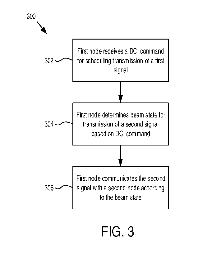
FIG. 3 is a flow chart of an example of a wireless communication method.
FIG. 4 is a flow chart of another example of a wireless communication method.
2
CA 03163114 2022- 6- 27
WO 2021/243671
PCT/CN2020/094509
DETAILED DESCRIPTION
The present description describes systems, apparatuses, and methods for
wireless
communication that determine a beam state for transmission of a second signal
between multiple
nodes in a wireless system based on a downlink control information (DCI)
command used to
schedule transmission of a first signal. Additionally, various embodiments may
further include
determining whether to perform the first signal transmission, determining the
beam state to perform
the second transmission according to a second transmission parameter, and/or
determining when to
use the beam state for the second transmission. Overhead and resources may be
reduced under
such wireless communication schemes. Such wireless communication schemes may
be
particularly advantageous for wireless systems that have relatively large
signaling overhead to
update the beam states, and for nodes that have multi-panel and/or multi-
transmission and
reception point (TRP) configurations, such as configured to communicate
according to New Radio
(NR) technology.
In further detail, Fig. 1 shows a diagram of an example wireless communication
system
100 including a plurality of communication nodes that are configured to
wirelessly communicate
with each other. The communication nodes include a first node 102 and a second
node 104.
Various other examples of the wireless communication system 100 may include
more than two
communication nodes.
In general, each communication node is an electronic device, or a plurality
(or network
or combination) of electronic devices, that is configured to wirelessly
communicate with another
node in the wireless communication system, including wirelessly transmitting
and receiving signals.
In various embodiments, each communication node may be one of a plurality of
types of
communication nodes.
One type of communication node is a user device. A user include a single
electronic
device or apparatus, or multiple (e.g., a network of) electronic devices or
apparatuses, capable of
communicating wirelessly over a network. A user device may include or
otherwise be referred to
as a user teiminal or a user equipment (UE). Additionally, a user device may
be or include, but
not limited to, a mobile device (such as a mobile phone, a smart phone, a
tablet, or a laptop
computer, as non-limiting examples) or a fixed or stationary device, (such as
a desktop computer or
3
CA 03163114 2022- 6- 27
WO 2021/243671
PCT/CN2020/094509
other computing devices that are not ordinarily moved for long periods of
time, such as appliances,
other relatively heavy devices including Internet of things (IoT), or
computing devices used in
commercial or industrial environments, as non-limiting examples).
A second type of communication node is a wireless access node. A wireless
access
node may comprise one or more base stations or other wireless network access
points capable of
communicating wirelessly over a network with one or more user devices and/or
with one or more
other wireless access nodes. For example, the wireless access node 104 may
comprise a 4G LTE
base station, a 5G NR base station, a 5G central-unit base station, a 5G
distributed-unit base station,
a next generation Node B (gNB), an enhanced Node B (eNB), or other base
station, or network in
various embodiments.
As shown in Fig. 1, each communication node 102, 104 may include transceiver
circuitry 106 coupled to an antenna 108 to effect wireless communication. The
transceiver
circuitry 106 may also be coupled to a processor 110, which may also be
coupled to a memory 112
or other storage device. The processor 110 may be configured in hardware
(e.g., digital logic
circuitry, field programmable gate arrays (FPGA), application specific
integrated circuits (ASIC),
or the like), and/or a combination of hardware and software (e.g., hardware
circuitry (such as a
central processing unit (CPU)) configured to execute computer code in the form
of software and/or
firmware to carry out functions). The memory 112, which may be in the form of
volatile memory,
non-volatile memory, combinations thereof, or other types of memory, may be
implemented in
hardware, and may store therein instructions or code that, when read and
executed by the processor
110, cause the processor 110 to implement various functions and/or methods
described herein.
Also, in various embodiments, the antenna 108 may include a plurality of
antenna elements that
may each have an associated phase and/or amplitude that can be controlled
and/or adjusted, such as
by the processor 110. Through this control, a communication node may be
configured to have
transmit-side directivity and/or receive-side directivity, in that the
processor 110, and/or the
transceiver circuitry 106, can perform beam forming by selecting a beam from
among a plurality of
possible beams, and transmit or receive a signal with the antenna radiating
the selected beam.
Additionally, in various embodiments, the communication nodes 102, 104 may be
configured to wireles sly communicate with each other in or over a mobile
network and/or a
4
CA 03163114 2022- 6- 27
WO 2021/243671
PCT/CN2020/094509
wireless access network according to one or more standards and/or
specifications. In general, the
standards and/or specifications may define the rules or procedures under which
communication
nodes 102, 104 can wirelessly communicate, which may include those for
communicating in
millimeter (mm)-Wave bands, and/or with multi-antenna schemes and beamforming
functions. In
addition or alternatively, the standards and/or specifications are those that
define a radio access
technology and/or a cellular technology, such as Fourth Generation (4G) Long
Term Evolution
(LTE), Fifth Generation (5G) New Radio (NR), or New Radio Unlicensed (NR-U),
as non-limiting
examples.
In the wireless system 100, the communication nodes 102, 104 are configured to
wirelessly communicate signals between each other. In general, a communication
in the wireless
system 100 between two communication nodes can be or include a transmission or
a reception, and
is generally both simultaneously, depending on the perspective of a particular
node in the
communication. For example, for a communication between the first node 102 and
the second
node 104, where the first node 102 is transmitting a signal to the second node
104 and the second
node 104 is receiving the signal from the first node 102, the communication
may be considered a
transmission for the first node 102 and a reception for the second node 104.
Similarly, where the
second node 104 is transmitting a signal to the first node 102 and the first
node 102 is receiving the
signal from the second node 102, the communication may be considered a
transmission for the
second node 104 and a reception for the first node 102. Accordingly, depending
on the type of
communication and the perspective of a particular node, when a first node is
communicating a
signal with a second node, the node is either transmitting the signal or
receiving the signal.
Hereafter, for simplicity, communications between two nodes are generally
referred to as
transmissions.
Additionally, signals communicated between communication nodes in the system
100
may be characterized or defined as a data signal or a control signal. In
general, a data signal is a
signal that includes or carries data, such multimedia data (e.g., voice and/or
image data), and a
control signal is a signal that carries control information that configures
the communication nodes
in certain ways in order to communicate with each other, or otherwise controls
how the
communication nodes communicate data signals with each other. Also, particular
signals can be
CA 03163114 2022- 6- 27
WO 2021/243671
PCT/CN2020/094509
characterized or defined as either an uplink (UL) signal or a downlink (DL)
signal. An uplink
signal is a signal transmitted from a user device to the wireless access node.
A downlink signal is
a signal transmitted from a wireless access node to a user device. Also,
certain signals may
defined or characterized by combinations of data/control and uplink/downlink,
including uplink
control signals, uplink data signals, downlink control signals, and downlink
data signals.
For at least some specifications, such as 5G NR, an uplink control signal is
also referred
to as a physical uplink control channel (PUCCH), an uplink data signal is also
referred to as a
physical uplink shared channel (PUSCH), a downlink control signal is also
referred to as a physical
downlink control channel (PDCCH), and a downlink data signal is also referred
to as a physical
downlink shared channel (PDSCH).
Also, some signals communicated in the system 100 may be defined or
characterized as
reference signals (RS). In general, a reference signal may be recognized in
the system 100 as a
signal other than a shared channel signal or a control signal, although a
reference signal may be an
uplink reference signal or a downlink reference signal. Non-limiting examples
of reference
signals used herein, and as defined at least in 5G NR, include a demodulation
reference signal
(DM-RS), a channel-state information reference signal (CSI-RS), and a sounding
reference signal
(SRS). A DM-RS is used for channel estimation to allow for coherent
demodulation. For example,
a DMRS for a PUSCH transmission allows a wireless access node to coherently
demodulate the
uplink shared channel signal. A CSI-RS is a downlink reference signal used by
a user device to
acquire downlink channel state information (CSI). A SRS is an uplink reference
signal
transmitted by a user device and used by a wireless access node for uplink
channel-state estimation.
Additionally, a signal may have an associated resource that, in general,
provides or
identifies time and/or frequency characteristics for transmission of the
signal. An example time
characteristic is a temporal positioning of a smaller time unit over which the
signal spans, or that
the signal occupies, within a larger time unit. In certain transmission
schemes, such as orthogonal
frequency-division multiplexing (OFDM), a time unit can be a sub-symbol (e.g.,
a OFDM
sub-symbol), a symbol (e.g., a OFDM symbol), a slot, a sub-frame, a frame, or
a transmission
occasion. An example frequency characteristic is a frequency band or a sub-
carrier in or over
which the signal is carried. Accordingly, as an example illustration, for a
signal spanning N
symbols, a resource for the signal may identify a positioning of the N symbols
within a larger time
6
CA 03163114 2022- 6- 27
WO 2021/243671
PCT/CN2020/094509
unit (such as a slot) and a subcarrier in or over which the signal is carried.
Fig. 2 shows a block diagram of a plurality of modules of a communication
node,
including a physical layer (PHY) module 202, a medium-access control (MAC)
module 204, a
radio-a link control (RLC) module 206, a package data convergence protocol
(PDCP) module 208,
and a radio resource control (RRC) module 210. In general, as used herein, a
module is an
electronic device, such as electronic circuit, that includes hardware or a
combination of hardware
and software. In various embodiments, a module may be considered part of, or a
component of,
or implemented using one or more of the components of a communication node of
Fig. 1, including
a processor 110, a memory 112, a transceiver circuit 106, or the antenna 108.
For example, the
processor 110, such as when executing computer code stored in the memory 112,
may perform the
functions of a module. Additionally, in various embodiments, the functions
that a module
performs may be defined by one or more standards or protocols, such as 5G NR
for example. In
various embodiments, the PHY module 202, the MAC module 204, the RLC module
206, the
PDCP module 208, and RRC module 210 may be, or the functions that they perform
may be, part
of a plurality of protocol layers (or just layers) into which various
functions of the communication
node are organized and/or defined. Also, in various embodiments, among the
five modules
202-210 in Fig. 2, the PHY module 202 may be or correspond to the lowest
layer, the MAC
module 204 may be or correspond to the second-lowest layer (higher than the
PHY module 202),
the RLC module 206 may be or correspond to the third lowest layer (higher than
the PHY module
202 and the MAC module 204), the PDCP module 208 may be or correspond to the
fourth-lowest
layer (higher than the PHY module 202, the MAC module 204, and the RLC module
206), and the
RRC module 210 may be or correspond to the fifth lowest layer (higher than the
PHY module, the
MAC module 204, the RLC module 206, and the PDCP module 208). Various other
embodiments may include more or fewer than the five modules 202-210 shown in
Fig. 2, and/or
modules and/or protocol layers other than those shown in Fig. 2.
The modules of a communication node shown in Fig. 2 may be perform various
functions and communicate with each other, such as by communicating signals or
messages
between each other, in order for the communication node to send and receive
signals. The PHY
layer module 202 may perform various functions related to encoding, decoding,
modulation,
7
CA 03163114 2022- 6- 27
WO 2021/243671
PCT/CN2020/094509
demodulation, multi-antenna mapping, as well as other functions typically
performed by a physical
layer.
The MAC module 204 may perform or handle logical-channel multiplexing and
demultiplexing, hybrid automatic repeat request (HARQ) retransmissions, and
scheduling-related
functions, including the assignment of uplink and downlink resources in both
the frequency domain
and the time domain. Additionally, the MAC module 204 may determine transport
formats
specifying how a transport block is to be transmitted. A transport format may
specify a
transport-block size, a coding and modulation mode, and antenna mapping. By
varying the
parameters of the transport format, the MAC module 204 can effect different
data rates. The
MAC module 204 may also control distributing data from flows across different
component
carriers or cells for carrier aggregation.
The RLC module 206 may perform segmentation of service data units (SDU) to
suitably
sized protocol data units (PDU). In various embodiments, a data entity from/to
a higher protocol
layer or module is called a SDU. and the corresponding data entity to/from a
lower protocol layer
or module is called a PDU. The RLC module 206 may also perform retransmission
management
that involves monitoring sequence numbers in PDUs in order to identify missing
PDUs.
Additionally, the RLC module 206 may communicate status reports to enable
retransmission of
missing PDUs. The RLC module 206 may also be configured to identify errors due
to noise or
channel variations.
The package data convergence protocol module 208 may perform functions
including,
but not limited to, Internet Protocol (IP) header compression and
decompression, ciphering and
deciphering, integrity protection, retransmission management, in-sequence
delivery, duplicate
removal, dual connectivity, and handover functions.
The RRC module 210 may be considered one of one or more control-plane protocol
responsible for connection setup, mobility, and security. The RRC module 210
may perform
various functions related to RAN-related control-plane functions, including
broadcast of system
information; transmission of paging messages; connection management, including
setting up
bearers and mobility; cell selection, measurement configuration and reporting;
and handling device
capabilities. In various embodiments, a communication node may communicate RRC
messages
8
CA 03163114 2022- 6- 27
WO 2021/243671
PCT/CN2020/094509
using signaling radio bearers (SRBs) according to protocols defined by one or
more of the other
modules 202-210.
Various other functions of one or more of the other modules 202-210 may be
possible in
any of various embodiments.
Fig. 3 is a flow chart of an example method 300 for wireless communication. At
block
302, a first node receives a downlink control information (DCI) command, such
as from a second
node. In various embodiments, the first node that receives the DCT command is
a user device, and
the second node is a wireless access node. In addition, in various
embodiments, the DCI
command is generated and sent to the first node in order to schedule
transmission of the first signal.
Scheduling the transmission may include various tasks, such as determining one
or more resources
involved to communicate (transmit or receive) the first signal, a beam (such
as a transmit beam or a
receive beam) with which to communicate the first signal, and/or a time at
which to communicate
the first signal, as non-limiting examples. In addition, in various
embodiments, the first signal
includes at least one of: a PDCCH, a PUCCH, a CSI-RS, a SRS, a PUSCH, or a
PDSCH.
At block 304, in response to, or based on, receiving the DCI command, the
first node
may determine a beam state for transmission of the second signal. In various
embodiments, the
second signal includes at least one of: a PDCCH, a PUCCH, a PUSCH, a PDSCH, a
CSI-RS, or a
SRS. Also, in general, a beam state is a set of one or more parameters that a
communication node
uses to communicate signals with one or more other communication nodes. In at
least some
embodiments, some or all of the parameters are defined by and/or used in
accordance with 5G NR.
In addition or alternatively, a beam state comprises at least one of: one or
more quasi co-location
(QCL) states, one or more transmission configuration indicator (TCI) states,
spatial relation
information, reference signal information, spatial filter information, or
precoding information. In an
embodiment, the second signal is not scheduled by the DCI command. In an
embodiment, the
second signal is different from the first signal, such as with different
types, or with different
communication resources (at least including frequency domain, time domain).
Also, for at least some embodiments, the DCI command includes beam state
information that the first node uses to determine the beam state. For example,
the beam state
information may explicitly indicate the beam state, or may implicitly indicate
the beam state, such
9
CA 03163114 2022- 6- 27
WO 2021/243671
PCT/CN2020/094509
as by including a value, such as an index value, that indicates the beam
state. Also, for at least
some embodiments, the beam state information included in a DCI command may be
included in at
least one TCI field or at least one reference signal resource indicator (SRI)
field.
Also, for at least some embodiments, a DCI command indicates one of a
plurality of
predetermined combinations of beam states, where each predetermined
combination includes one
or more beam states. For such embodiments, the first node may determine the
beam state for the
transmission of the first signal and/or for transmission of the second signal
by determining which
of the plurality of possible beam state combinations is indicated in the DCI
command. For at least
some embodiments, each predetermined combination is associated with a
respective beam state
indication value, and the beam state indication value may be included in the
DCI command.
Upon receipt of the DCI command, the first node may identify the beam state
indication value, and
in turn, determine the beam state combination. In particular embodiments, the
first node may be
configured with a lookup table that associates beam state indication values
with predetermined
beam state combinations. An example lookup table is provided as follows:
beam state indication value First beam state Second
beam state
0 beam state #0 none
1 beam state #1 none
2 beam state #0 beam
state #1
Table 1: Example lookup table mapping beam state indication values and
predetermined beam state
combinations
In the example lookup Table 1, the wireless system 100 uses three
predetermined beam
state combinations of two beam states (beam state #0 and beam state #1), where
each
predetermined beam state combination includes one or more beam states. For
example, a first
beam state combination includes only beam state #0, a second beam state
combination includes
only beam state #1, and a third beam state combination includes beam state #0
and beam state #1.
Each predetermined beam state combination is associated with a respective one
of a plurality of
beam state indication values. A given beam state indication value may be
included in a DCI
command. Upon receipt of the DCI command, the first node may determine the
given beam state
indication value, and then, using the lookup table, determine a predetermined
beam state
CA 03163114 2022- 6- 27
WO 2021/243671
PCT/CN2020/094509
combination. The first node may then determine to use that beam state
combination for the beam
state for transmission of the first and second signals.
Additionally, for at least some embodiments where the beam state is indicated
in at least
one TCI field of the DCI command, the DCI command has a DCI format 1_1, a DCI
format 1_2, a
DCI format 0_1, or a DCI format 0_2. Additionally, for at least some
embodiments where the
beam state is indicated in at least one SRI field of the DCI command, the DCI
command has a DCI
format 0_1 or a DCI format 0_2.
In addition or alternatively, in various embodiments where the beam state is
indicated in
at least one SRI field, and the second signal is a downlink signal, the beam
state indicated by the at
least one SRI field may include (e.g., only include) a QCL type D reference
signal. In addition or
alternatively, in various embodiments where the beam state is indicated in at
least one TCI field,
and the second signal is an uplink signal, the beam state indicated by the at
least one TCI field may
include (e.g., only include) a QCL type D reference signal.
As mentioned, for some example embodiments, the second signal may be a PDCCH.
In various of these embodiments, the PDCCH is a PDCCH in all control resource
sets (CORESETs)
in a bandwidth part or a cell, a PDCCH in a CORESET on which the first node
receives the DC'
command, a PDCCH in a CORESET pool on which the first node receives the DCI
command, a
PDCCH in a CORESET or a CORESET pool that is associated with the beam state
indicated in the
DCI command, or a PDCCH that is related to a same CORESET or a same CORESET
pool as the
DCI command.
For other example embodiments, the second signal is a PUCCH, as mentioned. In
various of these embodiments, the PUCCH may be a PUCCH in all PUCCH resources
in a
bandwidth part or a cell, a PUCCH indicated by a PUCCH resource indicator
(PRI) in the DCI
command, a PUCCH belonging to a same PUCCH resource group indicated by a PUCCH
resource
indicator in the DC1 command, or a PUCCH associated with a spatial
relationship related to (such
as by having a QCL relationship with) a CORESET in which the first node
receives the DCI
command. In general, a user device may be configured with a plurality of PUCCH
resources used
for the PUCCH transmission, and the user device can use the determined beam
state to update the
beam state of at least one PUCCH resource with which the first node is
configured. Also, in
11
CA 03163114 2022- 6- 27
WO 2021/243671
PCT/CN2020/094509
general, for uplink communication, when a PUCCH transmission is scheduled, a
PUCCH resource
may be indicated by the wireless access node. Additionally, in general, for
downlink
communication, a user device may be configured with one or more CORESETs. The
user device
may monitor occasions indicated by the one or more CORESETs.
For still other embodiments, the second signal may be a reference signal (RS),
such as a
SRS or a CSI-RS, as mentioned. For such embodiments, the reference signal
includes a reference
signal with all or part of configured RS resources, a reference signal with
all or part of RS
resources in a bandwidth part or a cell, or a reference signal with a
reference signal (RS) resource
determined by a RS resource set index or a RS resource index. In various of
these embodiments,
the RS resource index is activated by the DCI command. For at least some of
these embodiments,
the RS source is in a RS resource set that includes a highest resource set
index or a lowest resource
set index among a plurality of resource set indices for a plurality of RS
resource sets activated by
the DCI command.
Also, in various embodiments, where the second signal is a PDCCH, a PUCCH, a
PDSCH, a PUSCH, or a RS, the bandwidth part or the cell is determined
according to the DCI
command. For at least some of these embodiments, the bandwidth part or the
cell includes: a
bandwidth part or a cell where the DCI command is transmitted; a first
bandwidth part or a first
cell related to a second bandwidth part or a second cell where the DCI command
is transmitted
(e.g., by predeleimined mapping); or a first bandwidth part or a first cell
belonging to a same group
as a second bandwidth part or a second cell where the DCI command is
transmitted.
For still other embodiments, the second signal may be a PUSCH. In various of
these
embodiments, the PUSCH is scheduled to be transmitted or activated by a second
DCI command,
or the PUSCH is configured according to RRC parameters, such as
ConfiguredGrantConfig. Also,
in various embodiments, the first node, or the second node, may update a SRS
resource indicator
(SRI) (e.g., a SRI in rrc-ConfiguredUplinkGrant) with beam state information
in the DCI command
for a configured-grant type 1 PUSCH, and/or may update a SRI in a DCI command
that activated
or caused the PUSCH transmission with or by beam state information in the DCI
command for a
configured-grant type 2 PUSCH. Here, a configured-grant type 1 PUSCH
transmission refers to a
PUSCH transmission configured by ConfiguredGrantConfig, where rrc-
ConfiguredUplinkGrant is
12
CA 03163114 2022- 6- 27
WO 2021/243671
PCT/CN2020/094509
included in ConfiguredGrantConfig. In addition, a configured-grant type 2
PUSCH transmission
refers to a PUSCH transmission configured by ConfiguredGrantConfig, where
rrc-ConfiguredUplinkGrant is not included in ConfiguredGrantConfig.
Also, in various
embodiments, whether a configured-grant type (either type 1 or type 2) PUSCH
allow the first
node or the second node to update the beam state or communicate the PUSCH
according to the
beam state may depend on higher layer signaling (e.g, higher than the physical
layer (PHY)).
Also, in various embodiments, the first node, or the second node, determines a
SRI of
the PUSCH according to the beam state based on the DCI command. Also, in
various
embodiments where the second signal is a PUSCH, the PUSCH transmission is a
codebook-based
PUSCH transmission or a non-codebook based PUSCH transmission. For at least
some of these
embodiments, the beam state from the DCI command, the first node determines a
SRS resource for
transmission of the codebook-based PUSCH or transmission of the non-codebook-
based PUSCH.
In addition, for at least some of these embodiments, the first node determines
a SRS resource for
the codebook-based PUSCH transmission or the non-codebook-based PUSCH
transmission. For
at least some of these embodiments, the beam state comprises one of a
plurality of beam states, and
the first node determines one or more SRS resources for the non-codebook-based
PUSCH
transmission based on the plurality of beam states.
In still other example embodiments, the second signal is a PDSCH. For such
embodiments, the first node may schedule the PDSCH transmission by the DCI
command, where
the DCI command has a DCI format 1_0, a DCI format 1_1, or a DCI format 1_2.
Additionally, in various embodiments, the DCI command is a most recent DCI
command that includes the beam state received prior to receiving a second DCI
command that
schedules the second signal transmission.
In addition or alternatively, in various embodiments, the first node may
determine the
beam state for transmission of the second signal based on the DCI command
according to a second
transmission parameter. In general, a second transmission parameter may
include any data or
information that indicates to a node whether to determine a beam state for the
second signal.
Additionally, for at least some of these embodiments, the second transmission
parameter is
included in RRC signaling, MAC layer signaling (e.g., a medium access control
control element
13
CA 03163114 2022- 6- 27
WO 2021/243671
PCT/CN2020/094509
(MAC-CE) commands), or physical layer signaling. In addition or alternatively,
the first node
determines the beam state based on the DCI command according to the second
transmission
parameter in response to, or when, the second transmission parameter is
enabled or provided. For
at least some of these embodiments, the second transmission parameter is
provided for a type of
second signal, such as at least one of a PDCCH, a PUCCH, a CSI-RS, a SRS, a
PDSCH, or a
PUSCH. In addition or alternatively, the type of second signal is determined
according to one of:
a predetermined type of second signal, a configured type of second signal
(e.g., configured by RRC
signaling), an indicated type of second signal (e.g., indicated by physical
layer signaling), or a DCI
format of the DCI command.
For example, in various embodiments, the second transmission parameter in the
DCI
command includes an N-bit binary value, where N is an integer of 1 or more.
Accordingly, a
given N-bit binary value may be one of 2N possible binary values. Each binary
value may
indicate whether the second transmission parameter is enabled for one or more
given second signal
types. In particular embodiments, a given signal type is a PDCCH or a PUCCH.
To illustrate, in
a particular example embodiment where N is two, a 2-bit value "00" indicates
that the beam state
included in the DCI command is not used to determine the beam state of a PDCCH
transmission
and/or a PUCCH transmission; a 2-bit value -01" indicates that the beam state
included in the DCI
command is not used to determine the beam state of a PDCCH transmission, but
can be used for
the beam state of a PUCCH transmission; a 2-bit value "11" indicates that the
beam state included
in the DCI command is used to determine the beam state of a PDCCH transmission
and the beam
state of a PUCCH transmission.
For another example, the second transmission parameter in the DCI command
includes
a 1-bit binary value that indicates whether the second transmission parameter
is enabled for a
predetermined or a configured type of second signal, e.g. a PDCCH. A 1-bit
binary value -0"
indicates that the beam state included in the DCI command is not used to
determine the beam state
of the configured type of second signal (e.g., a PDCCH); and a 1-bit binary
value "1" indicates that
the beam state included in the DCI command is used to determine the beam state
of the configured
type of second signal (e.g., a PDCCH).
Additionally, in various embodiments, the predetermined or configured type of
second
14
CA 03163114 2022- 6- 27
WO 2021/243671
PCT/CN2020/094509
signal may be a PDCCH and/or a PUCCH; and/or the type of second signal is
related to the DCI
format. For example, the beam state of a PDCCH transmission is determined
according to the
DCI format 1_1 or 1_2; and/or the beam state of a PUCCH transmission is
determined according to
the DCI format 0_1 or 0_2.
Also, in various embodiments, the beam state that the first node determines
based on the
DCI command is one of a plurality of beam states of a beam state group. For at
least some of
these embodiments, the beam state group is related to or associated with one
or more types of
second signal, such as at least one of a PDCCH, a PUCCH, a CSI-RS, a SRS, a
PDSCH, or a
PUSCH. In addition or alternatively, the beam state group is determined
according to MAC layer
signaling or RRC signaling.
In addition or alternatively, in various embodiments, the first node may
determine the
beam state for the transmission of the second signal based on the DCI command
after a
predetermined time point, or after a predetermined time period after a
predetermined time point.
In various embodiments, the predetermined time point is one of: a time of
receiving the DCI
command, a time of the transmission of the second signal, a time of a second
DC1 command which
schedules the second signal, or a time that a response signal related to the
DCI command is
communicated. In particular embodiments, the time of receiving the DCI command
corresponds
to a time of receiving a last symbol of a PDCCH transmission that includes the
DCI command, or
an initial symbol immediately after the last symbol. In addition or
alternatively, in various
embodiments, the predetermined time period comprises one or more time units,
where each time
unit includes a slot, a symbol, a radio frame, a physical frame, a sub-frame
of the radio frame or the
physical frame, or a seconds-based unit (e.g., milliseconds, microseconds,
nanoseconds, etc.). In
an embodiment, the predetermined time period comprises 3 slots. In an
embodiment, the
predetermined time period depends on UE capability.
Additionally, in various embodiments, the first node may transmit a response
signal to
the second node in response to receiving the DCI command. For such
embodiments, the
predetermined time point corresponds to a time at which the first node
transmits the response signal.
For at least some embodiments, the response signal is a PUSCH scheduled by the
DCI command, a
first hybrid automatic repeat request (HARQ) signal for a PDSCH transmission
scheduled by the
CA 03163114 2022- 6- 27
WO 2021/243671
PCT/CN2020/094509
DCI command, or a second HARQ signal for the DCI command. In various of these
embodiments, when the response signal includes the first HARQ signal, the HARQ
signal is a
positive acknowledgment (HARQ-ACK) or a negative acknowledgement (HARQ-NACK).
Also, for at least some embodiments where the response signal includes a
PUSCH, the
first node determines the beam state for the transmission of the second signal
after the
predetermined time period after the predetermined time point dependent on: the
first node not
detecting any other DCI commands before the predetermined time point, or
before the
predetermined time period after the predetermined time point; or the first
node detecting one or
more other DCI commands before the predetermined time period after the
predetermined time
point and the one or more other DCI commands is not used to determine the beam
state of the
second signal.
Also, for at least some embodiments where the response signal includes a
PUSCH, the
first node detects a second response signal from the second node before the
predetermined time
point, or before the predetermined time period after the predetermined time
point. Upon doing so,
the first node determines the beam state for the transmission of the second
signal after the
predetermined time period after the predetermined time point, or after a
second predetermined time
period after the predetermined time point. Also. for at least some of these
embodiments, where
the second response signal comprises a DCI format, the second node schedules a
second PUSCH
transmission with a same hybrid automatic repeat request (HARQ) process number
as for a first
PUSCH transmission of the first response signal with a toggled new-data
indicator (NDI) field
value.
At block 306, the first node may communicate the second signal with a second
node
according to the beam state. As non-limiting examples, the first node may
communicate the
second signal according to a scheduling indicated by the beam state, may
communicate with a
selected beam (e.g., a transmit beam or a receive beam) indicated by the beam
state, may encode,
decode, modulate, or demodulate according to the beam state, and/or using one
or more resources
indicated by the beam state. In various embodiments, the first node may
communicate the second
signal with the second node by either transmitting the second signal to the
second node, or by
receiving the second signal from the second node. Also, in various
embodiments, the first node
16
CA 03163114 2022- 6- 27
WO 2021/243671
PCT/CN2020/094509
may communicate the second signal after communicating the first signal, may
communicate the
second signal before communicating the first signal, or may communicate the
second signal
without communicating the first signal. For such latter situations, the first
node may determine
the beam state for a first transmission, such as based on a DCI command, but
then expressly
determine not to communicate the first signal.
Additionally, for at least some embodiments, the first node may determine
whether to
communicate the first signal with the second node. For example, in various
embodiments, when a
location of a user device changes, the wireless access node may need to update
a beam that the user
device uses to communicate with the wireless access node. If there is a need
to communicate data
between the wireless access node and the user device, the nodes may use a DCI
command to
schedule transmission of a first signal (on a PDSCH or a PUSCH) to communicate
the data, and
may further use the beam state information in the DCI command to determine the
beam state for
transmission of a second signal. However, in various situations, the two nodes
may not have data
to communicate, and so therefore do not have a first signal to communicate
with each other. For
at least some of these situations, the two nodes may still have determined a
beam state for
transmission of the first signal, even though the first signal is not
communicated, or in some cases
not even scheduled by a DCI command to be communicated. For such embodiments,
the two
nodes may still determine that the beam state information that would have been
used to transmit a
first signal, can still be used for transmission of a second signal, even
though they do not
communicate the first signal.
FIG. 4 is an example wireless communication method 400 that determines a beam
state
for transmission of a second signal based on a DCI command used to schedule
transmission of a
first signal, and further whether to communicate the first signal. At block
402, the first node may
determine a beam state for transmission of a second signal based on a DCI
command used for
scheduling a transmission of a first signal, as previously described for block
304 of FIG. 3. At
block 404, the first node may determine whether to communicate the first
signal with the second
node. In various embodiments, the first node may use a first transmission
parameter to determine
whether to communicate the first signal with the second mode. In general, a
first transmission
parameter may include any data or information that indicates to a node whether
to communicate the
17
CA 03163114 2022- 6- 27
WO 2021/243671
PCT/CN2020/094509
first signal. In various embodiments, the first node may use RRC signaling,
physical layer (PHY)
signaling, or MAC layer signaling (e.g., a media access control element (MAC-
CE) command) to
carry the first transmission parameter.
In addition, in various embodiments, the first node may determine not to
communicate
the first signal in response to the first transmission parameter indicating
not to communicate the
first signal, or an absence of the first transmission parameter. On the other
hand, the first node
may determine to communicate the first signal in response to first
transmission parameter
indicating to communicate the first signal, or a presence of the first
transmission parameter.
Herein, a presence of the first transmission parameter may refer to a
parameter that is provided to a
node, or with which the node is configured or reconfigured. Accordingly, an
absence of the first
transmission parameter may refer to a parameter that is not provided to a
node, or with which the
node is not configured or not reconfigured.
In other example embodiments, a DCI command is used to carry, include, or
indicate
the first transmission parameter. For at least some of these embodiments, the
first signal
comprises an uplink signal, and the DCI command includes an uplink shared
channel (UL-SCH)
indicator that includes the first transmission parameter. For at least some of
these embodiments,
the UL-SCH indicator includes a '0' value to indicate not to communicate the
uplink signal. In
addition or alternatively, the DCI command may include a CSI request field
that includes a value
indicating not to send a CSI report. Such embodiments allow a DCI command to
include both a
US-SCH indicator field having a '0' value and a CSI request field indicating
not to send a CSI
report. In various embodiments, the first node may utilize RRC protocols
and/or signaling to
configure the DCI command to indicate both not to communicate an uplink signal
and not to send a
CSI report.
In addition, for at least some other embodiments, the first signal comprises a
downlink
signal, and the DCI command includes a downlink shared channel (DL-SCH)
indicator field that
comprises the first transmission parameter. For at least some of these
embodiments, the DL-SCH
indicator includes a '0' value to indicate not to communicate the downlink
signal. In various
embodiments, the first node may utilize RRC protocols and/or signaling to
include the first
transmission parameter in the DL-SCH indicator field to indicate whether to
communicate the first
18
CA 03163114 2022- 6- 27
WO 2021/243671
PCT/CN2020/094509
signal.
At block 404, if the first node determines to communicate the first signal,
then at block
406, the first node may communicate the first signal according to the beam
state determined at
block 402 with the second node. At block 408, the first node may communicate
the second signal
according to the beam state determined at block 402. In various embodiments,
such as indicated
in FIG. 4, the first node may communicate the first signal first, and then
communicate the second
signal. In other embodiments, the first node may communicate the second signal
first, and then
communicate the first signal. Various ways and/or orders of communicating both
the first signal
and the second signal may be possible. Referring back to block 404, if the
first node determines not
to communicate the first signal, then the method 400 may proceed directly to
block 408, where the
first node communicates the second signal without communicating the first
signal. Additionally,
in various embodiments, the first node may determine to the beam state for
transmission of the
second signal before determining whether to communicate the first signal, as
indicated in FIG. 4.
In other embodiments, the first node may determine whether to communicate the
first signal before
determining the beam state for transmission of the second signal.
The description and accompanying drawings above provide specific example
embodiments and implementations. The described subject matter may, however, be
embodied in
a variety of different forms and, therefore, covered or claimed subject matter
is intended to be
construed as not being limited to any example embodiments set forth herein. A
reasonably broad
scope for claimed or covered subject matter is intended. Among other things,
for example,
subject matter may be embodied as methods, devices, components, systems, or
non-transitory
computer-readable media for storing computer codes. Accordingly, embodiments
may, for
example, take the form of hardware, software, firmware, storage media or any
combination thereof.
For example, the method embodiments described above may be implemented by
components,
devices, or systems including memory and processors by executing computer
codes stored in the
memory.
Throughout the specification and claims, terms may have nuanced meanings
suggested
or implied in context beyond an explicitly stated meaning. Likewise, the
phrase "in one
embodiment/implementation" as used herein does not necessarily refer to the
same embodiment
19
CA 03163114 2022- 6- 27
WO 2021/243671
PCT/CN2020/094509
and the phrase "in another embodiment/implementation" as used herein does not
necessarily refer
to a different embodiment. It is intended, for example, that claimed subject
matter includes
combinations of example embodiments in whole or in part.
In general, terminology may he understood at least in part from usage in
context. For
example, terms, such as "and", "or", or "and/or," as used herein may include a
variety of meanings
that may depend at least in part on the context in which such terms are used.
Typically, "or" if
used to associate a list, such as A, B or C, is intended to mean A, B, and C,
here used in the
inclusive sense, as well as A, B or C, here used in the exclusive sense. In
addition, the term "one
or more" as used herein, depending at least in part upon context, may be used
to describe any
feature, structure, or characteristic in a singular sense or may be used to
describe combinations of
features, structures or characteristics in a plural sense. Similarly, terms,
such as "a," "an," or "the,"
may be understood to convey a singular usage or to convey a plural usage,
depending at least in
part upon context. In addition, the term "based on" may be understood as not
necessarily
intended to convey an exclusive set of factors and may, instead, allow for
existence of additional
factors not necessarily expressly described, again, depending at least in part
on context.
Reference throughout this specification to features, advantages, or similar
language
does not imply that all of the features and advantages that may be realized
with the present solution
should be or are included in any single implementation thereof. Rather,
language referring to the
features and advantages is understood to mean that a specific feature,
advantage, or characteristic
described in connection with an embodiment is included in at least one
embodiment of the present
solution. Thus, discussions of the features and advantages, and similar
language, throughout the
specification may, but do not necessarily, refer to the same embodiment.
Furthermore, the described features, advantages and characteristics of the
present
solution may be combined in any suitable manner in one or more embodiments.
One of ordinary
skill in the relevant art will recognize, in light of the description herein,
that the present solution
can be practiced without one or more of the specific features or advantages of
a particular
embodiment. In other instances, additional features and advantages may be
recognized in certain
embodiments that may not be present in all embodiments of the present
solution.
CA 03163114 2022- 6- 27