Note: Descriptions are shown in the official language in which they were submitted.
WO 2021/134117
PCT/AU2021/050002
1
SAFETY CORRIDOR ARRANGEMENT
[0001] The present invention relates to a safety corridor arrangement, and in
particular to
safety corridor arrangement to direct people to safety in case of emergency.
BACKGROUND TO THE INVENTION
[0002] Fire is an extremely dangerous and frightening emergency. Smoke quickly
fills a
room and reduces the visibility to very low. A person will be disorientated,
and in a state
of stress and shock, and with the reduced visibility may struggle to find
their way out of
the room, out of the building and towards safety. Current fire alarms can
detect smoke
and alert the occupants to the fire, however, fire can spread very quickly and
the smoke
may already be thick before a person has started to try to leave the building.
It is likely
that the power is off and no additional light is available, fires often
occurring at night when
the occupants are asleep. In this case a person may be choking on smoke, and
in the
dark trying to locate a doorway, and the way out of the building.
[0003] A similar problem was identified in emergency situations for planes,
and since
notable incidences, it is now compulsory to have floor lighting to light the
way to the exit
along an aisle. In a cinema, similar floor lighting may light the aisle.
However, these lights
rely on being lit all the time, which is not a suitable solution for a
domestic home, or many
situations. Further, the aisle lights only go so far to direct a person along
an aisle. In the
case of the cinema, often the exit itself is a distant corner and in the
absolute dark and is
not easily seen. The subject invention has developed a means to create a
virtual corridor
to light the way in the case of an emergency to direct a person to a doorway,
and
ultimately out of the building. This versatile and multi-faceted invention
enables a safety
corridor using laser light to be created to lead a person out of the building,
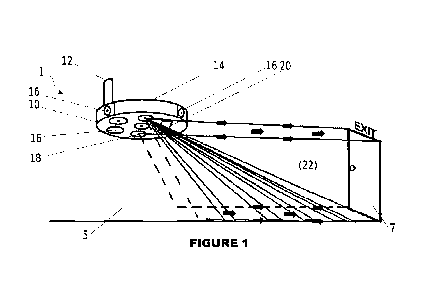
which can also
be used to advise people of where the safety exits are located in times of
safety and guide
a person safely away from the fire in times of danger. Although designed with
fire in mind,
the safety corridor arrangement may be used in any case where it is desired to
guide a
person away from danger. This may include any time of poor visibility but also
if there is
gas, blizzard conditions, high winds, any climatic, man-made or natural
condition where
it would be of benefit to be able to be guided to safety. Further, light,
sound and vibrations
CA 03163532 2022- 6- 30
WO 2021/134117
PCT/AU2021/050002
2
may all be used to guide along the safety corridor so that being able to see
is not a
requirement of use of the invention.
[0004] It is envisaged that other safety features will be included in the
arrangement, for
example, the safety corridor may be the location of firefighting equipment,
water including
hoses or drinking water, fire blankets, fire extinguishers, communication
devices,
anything of use during the emergency. Where the emergency is not fire there
may be
other suitable equipment positioned within the corridor and easily discerned
once there,
for use.
[0005] It is also envisaged that the safety arrangement will be adapted to be
incorporated
into a smoke detection system. The smoke detection system can be used to start
the
safety corridor arrangement, at first detection of smoke. In some forms of the
invention,
where there is a system of smoke detection, and a choice of safety corridors
the
occupants will be directed to the safest safety corridor and exit with least
smoke being
detected.
[0006] The inventor, has through long and careful development, invented a very
clever
new safety corridor arrangement which is likely to be a significant
improvement for safety
domestically and for commercial buildings. The invention may be conveniently
be referred
to as Laser Identified Fire Exit ("LIFE") for the ceiling mounted unit to
provide initial
direction of the exit, as well as the Point of Exit Audible Alarm ("PEAA") for
the door
mounted unit to highlight the point of exit. While each part LIFE and PEAA can
work
independently each as novel inventions, the combined invention provides a
significant
improvement over the art, and a significant safety improvement for use in the
future. The
combined safety systems provide a vertical laser direction system to the door,
and a door
mounted audible alarm to assist the person to find their way and leave the
room and the
danger. Further laser arrangements in the PEAA clearly illuminate the exit
doorway, and
assist to add to the laser corridor. In commercial applications a further
laser to the ceiling
can assist to find the exit, even if obscured by fallen goods or debris. The
LIFE and PEAA
systems together give an alarm, such as an audible directive and a visual
indication of
the direction of the exit. Together they provide a complete emergency corridor
arrangement to direct the person all the way to the final exit, and to safety.
CA 03163532 2022- 6- 30
WO 2021/134117
PCT/AU2021/050002
3
[0007] The following describes non-limiting examples of the invention being
used with
reference to a safety corridor arrangement for a fire in a commercial building
such as a
shop, or separately in a domestic setting, such as in family home. The
invention is useful
for any emergency and is not intended to be limited to fire, other than as
limited in the
claims. Further, the invention is useful to create a safety corridor in any
kind of building
or area and it is not intended to limit the invention, other than as limited
in the claims. For
example, in large commercial shopping precincts, cinemas, municipal buildings
or tourist
attractions use of the invention will be of particular use. The invention may
also be used
in outdoor arrangements such as industrially areas or loading bays.
[0008] For clarity, any prior art referred to herein, does not constitute an
admission that
the prior art forms part of the common general knowledge, in Australia or
elsewhere.
[0009] It is an object of the present invention to provide a safety corridor
arrangement that
at least ameliorates one or more of the aforementioned problems of the prior
art. It is a
further object of the invention to provide a method of use of a safety
corridor arrangement
that at least ameliorates one or more of the aforementioned problems of the
prior art.
SUMMARY OF THE INVENTION
[0010] Accordingly, the present invention provides a safety corridor
arrangement for use
in emergency situations, the safety corridor arrangement including:
an activation means;
an operation means, associated with an activation centre; and
a safety corridor suitable to guide or direct a person on a particular
pathway,
wherein, the activation centre, through activation of the activation means may
cause
operation of the operation means, and the operation means creates the safety
corridor to
guide a person along the safety corridor towards an exit.
[0011] Preferably, the safety corridor arrangement dramatically improves the
ability of a
person to find an exit. Preferably, the safety corridor arrangement helps a
person move
away from the emergency, towards an exit. Preferably, the safety corridor
arrangement
significantly shortens the time taken by a person to find an exit. Preferably,
a person is
rapidly guided by the safety corridor to a fire exit or the like, to speed the
person away
from the emergency.
CA 03163532 2022- 6- 30
WO 2021/134117
PCT/AU2021/050002
4
[0012] The emergency may be a fire. The emergency may be any emergency where
use
of the arrangement may be helpful. Some aspects of the invention may be used
independently, for example to make public announcements, even when the safety
corridor itself does not need to be activated. The emergency may, for example,
include
building collapse; earthquake; explosion; fire; flood; gas; terrorist attack;
tsunami; war
damage; or any combination thereof. The emergency may include poor visibility
for any
reason. The emergency may include smoke, gas, contaminants, or dust, for
example.
The emergency may include the conditions of very poor visibility reducing
ability to find
an exit or doorway.
[0013] The activation means may take any suitable form. The activation means
may
include a smoke detector. The smoke detector may detect smoke in any suitable
manner.
The smoke detector may be a linked system of smoke detectors whereby
activation
through smoke detection at one smoke detector, will cause activation of the
other smoke
detectors linked thereto. Areas or systems of smoke detectors may be included
in a
building such as a large commercial building, whereby sectors of smoked
detectors are
activated by one smoke detector detecting smoke. Many variants to the
activation means
including a smoke detector may be used to suit the particular application. The
activation
means may be activated by one or more smoke detector where the emergency
includes
smoke. Where the emergency does not include fire, other detectors can be
included.
These other detectors may include: chemicals in the air; dust; ground
movement;
temperature; oxygen levels; sound levels; water or moisture levels; or any
other indicator
of an emergency requiring rapid exit.
[0014] In a preferred form of the invention, the activation means is at a
separate location
to the rest of the safety corridor arrangement, for example a smoke detector
in one part
of the building may activate the safety corridor arrangement elsewhere to
direct people
to the fire exit. The activation means in any of its forms may be installed
remote to the fire
exit, and to the rest of the safety corridor arrangement. The activation means
can be any
suitable way that can be caused to detect an emergency and then cause
activation of the
rest of the safety corridor arrangement. For example, the activation means may
include
a sound detector. The sound detector may be configured to detect particular
noises or
noises over a certain loudness to activate the safety corridor arrangement.
Where a
particular noise is detected this may be an explosion or smashing glass, or
any type of
CA 03163532 2022- 6- 30
WO 2021/134117
PCT/AU2021/050002
noise associated with an emergency. The detection may include a decibel
detector, to
detect noise over a certain level in decibels. Preferably, a sound detector is
included as
an activation means and noise levels over 110 decibels will activate the
safety corridor
arrangement to guide a person towards an exit.
[0015] In some forms of the invention a manual over-ride or manual sound
activator of
the activation means may be included. Preferably, the activation means may be
activated
by a hand-held emergency horn, or other hand controlled sound alarm.
Preferably, the
activation by sound can be adjusted through increased or decreased sensitivity
to suit the
particular application. The activation system may be separate to the other
parts of the
system in some forms of the invention. Or the activation means may be
incorporated with
other parts of the system in some forms of the system. The activation means
may be or
include a means to be activated by a smoke detector. The activation may be due
to the
activation of the smoke detector in any manner, including through activation
by the sound
of the smoke detector being detected by the activation means to activate and
operate of
the safety corridor arrangement. In other words, there may be a direction
activation when
the smoke detector detects smoke through a linked system. In other forms, the
sound
itself is sufficient to activate safety corridor. It is particular useful to
be able to activate the
system using an external system either automatically in response to damage to
the
building causing a loud noise, manually through use of a hand-held horn, or
through an
automated or manual loud alarm sound operable in times of emergency.
[0016] A wireless network may be included, whereby the wireless network or
arrangement
communicates with the other parts of the safety corridor arrangement. The
wireless
connectivity of the safety corridor arrangement may be used for communication
of any
parts of the arrangement. Wireless monitoring and or control is preferably
included to
monitor the activation means, activation control and parts of the arrangement
that are in
operation. The monitoring may be undertaken remotely. The control of the
arrangement
may be able to be undertaken remotely, useful when the area of the building
containing
the safety corridor arrangement is on fire, or otherwise suffering an
emergency.
[0017] Preferably, on activation of the activation means the operation means
creates the
safety corridor. In other words, once the emergency is detected by the
activation means
the activation control is caused to operate the safety corridor to direct
people to an exit.
CA 03163532 2022- 6- 30
WO 2021/134117
PCT/AU2021/050002
6
Manual override control may be included for any of the features, for added
control. The
safety corridor may form part of another safety system for a building.
Preferably, a plurality
of safety corridor arrangements are included to direct a person from where
they are in the
building, through doorways and exits until they pass through an exit to the
outside and
safety. In some cases a single safety corridor arrangement is sufficient to
direct a person
from the room where they are to the fire exit, which leads to the outside. In
other domestic
arrangements, several doorways will need to be passed through before the final
exit to
the outside is found. In this arrangement multiple safety corridors will need
to be found
and followed to take you through the necessary doorways to pass to the door to
the
outside. In commercial arrangements, such as in an office block or shopping
centre, there
will be multiple corridors necessary to assist to direct all the people in the
many rooms
and areas through the doorways and fire exits to lead to the outside. In some
arrangements the safety corridors may lead to a muster station (such as when
used on a
ship) or to another safe area where people may gather before rescue.
[0018] The operation means may take any suitable means to cause the safety
corridor to
be operated with one or more alarms as suitable. Where a wireless network is
included
the operation means and the activation centre may be in wireless
communication. The
activation means may likewise be in wireless communication with the activation
centre.
The operation means may include any one or more of: visual; audible; physical;
or other
alerts to an emergency. The alerts may be direct or indirect through further
devices. The
alerts may be chosen from the following group: audible alarms; displays
including words
or symbols; flashing lights; lights; loud sirens; shaking devices; and
vibrations.
[0019] Preferably, the operation means is connected wirelessly to other parts
of the safety
arrangement. Preferably, the operation means is connected wirelessly to other
parts of
other safety equipment. The wireless communication may be through mobile
networks,
WIFI (Trade Mark), BLUETOOTH (Trade Mark) or any similar system or combination
of
systems. Preferably, an alert may be communicated to and or on from the
activation and
or operation means through use of wireless communication. A remote control may
be
used to control and operate the arrangement.
[0020] Preferably, a plurality of controls are included which on operation
create a visual
corridor to guide a person to a doorway, exit or other place of safety.
Preferably, one or
CA 03163532 2022- 6- 30
WO 2021/134117
PCT/AU2021/050002
7
more laser light is included to define a corridor. Preferably, multiple planes
are created to
define a corridor. Preferably, multiple horizontal planes are included and
created to define
a corridor. Horizontal and or vertical planes may be used to create the
virtual safety
corridor. Preferably, lasers are used similar to those used in the
entertainment industry.
These may be green lasers, as are frequently used or any suitable laser, safe
for the
application. Any suitable light or laser may be used to create the corridor.
Preferably,
lasers connect to other parts of the system to illuminate doorways, for
example to make
the doorways and exits particularly easy to see, even in times of poor
visibility. Optionally,
plastic tubes or similar may be used to convey the laser light, in some forms
of the
invention. The form of laser light used is preferably similar to those used in
the
entertainment industry by DJs to project a light beam, often to create an
aesthetic effect;
these are also used in night clubs and shows. This form of lasers are a safe,
low cost
laser, than can be turned on and easily and when turned off are unobtrusive.
Laser lights
such as those sold for DJs, SUNY DM-RGY200 may be suitable, or those used for
laser
stage lighting, being easy to use, and manipulate. For example 8 CH DMX 512
Pro
Scanner DJ Party KTV Show Projector Equipment Light or another suitable laser
is the
Beamz Cupid Double Multipoint laser with 12 GOBO pattern which projects
multiple
beams to the wall and ceiling. Other similar suitable lasers may be used
instead. The
speakers included to make the safety announcements and or sound the alarm may
be
any suitable speakers. Preferably, waterproof speakers are used. Preferably, a
plurality
of speakers are used in the system. LENOXX IP X& waterproof Bluetooth speakers
are
also a useful example. Preferably, the speakers are waterproof speakers.
Preferably, the
waterproof speakers are suitable to work in sprinklers or other emergency
water
situations.
[0021] Preferably, walls are defined of the corridor. The walls may be defined
by a sheet
of laser in the vertical plane, or through multiple horizontal plane lasers,
ending at the
same point to define a wall. Preferably, a ceiling is defined by the corridor.
The ceiling
may be defined by a sheet of laser in the horizontal plane, or through
multiple vertical
plane lasers, ending at the same point to define a ceiling. Preferably, a
floor is defined.
The floor may be defined by a sheet of laser in the vertical plane, or through
multiple
horizontal plane lasers, ending at the same point to define a floor. Most
preferably, used
of fanned out lasers mean that as a person moves forward towards an exit they
can see
CA 03163532 2022- 6- 30
WO 2021/134117
PCT/AU2021/050002
the laser on their hands, body or feet to help direct them to an exit.
Preferably, a corridor
is defined sufficient to guide or direct a person from one location to
another. Any one or
more of floor, left side wall, right side wall or ceiling of the virtual
corridor can be used to
direct a person towards an exit. Most preferably, all of floor, left side
wall, right side wall
and ceiling are at least to some extent defined to assist to direct a person
to an exit. The
defining may a single line of lights or laser. The defining may be a diffuse
fanned light to
create a side of the corridor. Fanned out lasers may be used in the horizontal
plane to
define multiple parts of the corridor. For example, just above the floor to
define a floor, or
likewise a ceiling. The orientation of the lasers and diffused laser light may
be altered to
suit the particular application.
[0022] Preferably, the corridor is invisible when not in use. Preferably, the
area of the
corridor is given additional fire proofing or safety. Preferably, useful items
in case of fire
are accessible from the corridor. For example, oxygen masks, water, safety
items or a
fire extinguisher. Any useful equipment for dealing with the emergency may be
included
close to the safety corridor for ready access in an emergency.
[0023] Preferably, a virtual corridor is created in response to emergency
activation to
direct a person from one location to another with guidance to do so in the
case of an
emergency.
[0024] Preferably, there is at least one laser to define a corridor towards an
exit doorway.
Preferably, a plurality of lasers may be included. Preferably, a pair of
lasers are included
to define the corridor toward the exit doorway.
[0025] Preferably, a point of exit arrangement is included. Preferably, the
point of exit
arrangement includes a bar which may be fitted above the exit doorway. The bar
may
take any suitable form. The point of exit arrangement may be formed in parts,
or arranged
around any suitable part of the exit doorway, in other forms of the invention.
Preferably,
the bar is installed above the exit doorway. Preferably, the bar extends on
either side of
the door frame. Preferably, there is an EXIT sign above the exit doorway. The
bar of the
point of exit arrangement may include any one or more of lasers, speakers,
lights and
signs.
CA 03163532 2022- 6- 30
WO 2021/134117
PCT/AU2021/050002
9
[0026] Preferably, the bar includes one or more Light Emitting Diode ("LED")
panel, able
to display messages through illuminating multiple LEDs. The messages may be
emergency messages. The messages may be programmed from a local or central
control
to display suitable words. Or the messages may be a generic message "emergency
exit".
The messages may be in response to Alert system messages as is used in a
particular
country.
[0027] Preferably, one or more lights are included below the bar to assist
illumination.
Preferably, a strip of lights is included below the bar. A strip of lights may
be included
anywhere about the doorway. The doorway may be illuminated I any suitable
manner.
[0028] Preferably, the point of exit arrangement includes an audible alarm. In
inferior
forms of the invention the point of exit arrangement may not include an
audible alarm.
Preferably, the point of exit arrangement includes one or more speakers.
Preferably, the
one or more speakers enables an audible alarm in times of emergency or fire.
Any
suitable number of speakers may be used. Preferably, the speakers are able to
give out
safety announcements. The speakers may be caused to give out any suitable
safety
message. The message may be programmed into the point of exit arrangement and
activated directly from the control centre.
[0029] Preferably, the point of exit arrangement includes one or more lasers.
Preferably,
one or more lasers are included to create an illuminated doorway. Preferably,
the
illuminated doorway is an illuminated exit, to guide a person out of a room.
The lasers
may illuminate any one or more part or edge of the doorway. There may be
lasers to
illuminate vertically. There may be lasers to illuminate horizontally. There
may be lasers
to illuminate in a diffuse or fanned form to give a spread of the light. The
fanned or diffuse
laser light gives the effect of a side wall of the safety corridor. Horizontal
or vertical laser
beams may be used as appropriate. Lasers may be used at either end of the
corridor to
give overlapping lasers to give the effect of a side wall to the corridor from
either end.
[0030] Preferably, the point of exit arrangement includes a laser directed at
the floor to
illuminate below the laser. Preferably, there are a pair of down pointed
lasers, each in the
generally area of the left and right sides of the door frame, to illuminate
the left and right
sides of the door frame. Any number of down pointing lasers may be used. The
lasers
may be any suitable angle, as appropriate to illuminate the doorway or exit.
Preferably,
CA 03163532 2022- 6- 30
WO 2021/134117
PCT/AU2021/050002
the down pointing lasers are directed to deflect the laser light in a
horizontal plane, fanning
out above the floor. The fanning out may create a virtual floor. The deflected
and fanning
out laser may be repeated at any height. The fanning out laser may be useful
as the laser
from an exit direction can be seen on a person, so they know they are heading
in the right
direction. The deflection may be 45 degrees. Any suitable angle may be used to
deflect
or disperse the laser. The angle may be any suitable angle for any of the
deflections. The
laser light from the down pointing lasers may be directed along plastic tubing
to form
edges. The laser light from the down pointed lasers preferably is deflected to
fan out to
illuminate and assist to form part of the side of the safety corridor.
Preferably, the laser
angles are adjusted to create the appropriate laser for the corridor.
Preferably, one or
more lasers is included angled to create a deflected or fanned out laser
light. The
deflection may be at 45 degrees. The deflection may be suitable to create a
"wall" of the
corridor. Any suitable arrangement may be used.
[0031] Preferably, one or more deflector is included below the down pointed
lasers.
Preferably, a pair of down pointed lasers are included and a pair of angled
lasers each
pair with one on either side of the doorway.
[0032] In commercial applications upward pointing lasers may be included,
directed to a
roof or ceiling. The upward laser may assist the exit to be seen from far
away.
[0033] Preferably, the point of exit arrangement assists by illuminating the
exit clearly.
Most preferably, use of the safety corridor arrangement with point of exit
arrangement to
provide a strongly illuminated corridor to direct people to the doorway and
exits. Several
corridors may be used to direct through a plurality of doorways to the
ultimate exit.
[0034] Accordingly, the invention also provides a method of use of a safety
corridor
arrangement, the safety corridor arrangement including an activation means and
an
operation means able to generate a safety corridor in an emergency to guide or
direct a
person in a direction, the method including the following steps:-
a) activation of the activation means in the case of an emergency;
b) operation of the operation means on activation to create a virtual
corridor;
and
C) directing a person to take the corridor as a safe
path.
CA 03163532 2022- 6- 30
WO 2021/134117
PCT/AU2021/050002
11
[0035] The safety corridor arrangement of the method may be the safety
corridor
arrangement of the invention in any of its forms or variants. The safety
corridor
arrangement may include a point of exit arrangement, according to any of its
variants.
BRIEF DESCRIPTION OF THE DRAWINGS
[0036] The invention will now be described in connection with non-limiting
preferred
embodiments with reference to the accompanying drawings, in which:
[0037] Figure 1 is a perspective schematic side view of a safety corridor
arrangement
according to a first preferred embodiment of the invention for use in a
commercial
property, a shop;
[0038] Figure 2 a perspective schematic front view of a safety corridor
arrangement
according to a second preferred embodiment of the invention for use in a
domestic home;
[0039] Figure 3 is a front view of a point of exit audible alarm, used as part
of the safety
corridor arrangement according to the first preferred embodiment of Figure 1
if used in a
commercial setting, or second preferred embodiment of Figure 2 if used in a
domestic
setting;
[0040] Figure 4 is a side view of the point of exit audible alarm of Figure 3;
[0041] Figure 5 is a perspective view of the point of exit audible alarm of
Figure 3 or 4,
with the door frame omitted for ease of illustration;
[0042] Figure 6 is a front view of the point of exit audible alarm of Figure 3
or 4, with the
door frame omitted for ease of illustration;
[0043] Figure 7 is a detailed perspective view of the point of exit audible
alarm of Figures
3 to 6, illustrating the speakers in particular; and
[0044] Figure 8 is a side view of the point of exit audible alarm of Figures 3
to 7, illustrating
the laser system.
CA 03163532 2022- 6- 30
WO 2021/134117
PCT/AU2021/050002
12
DETAILED DESCRIPTION OF THE DRAWINGS INCLUDING A BEST METHOD
[0045] Referring to Figure 1 a first preferred embodiment of the invention
will be
described, where safety corridor arrangement 1, is installed in room 5
including exit 7, a
door in a doorway with EXIT written above in accordance with safety
requirements. Room
is a commercial property room, and as illustrated is a windowless shop in a
large
shopping centre. As would be understood in normal circumstances shops are well
lit and
easy to move around, however, in an emergency the light levels are very low.
When the
emergency is fire the low light and smoke make it very difficult to see, or to
locate an exit,
and the safest routeway from the fire. Room 5 is shown with a ceiling, walls
and floor
(none of which are labelled) in the usual manner, and safety corridor
arrangement 1 is
installed in the ceiling and floor in the main. Laser operation unit 10
contains most of the
parts of safety corridor arrangement 1, and is usefully installed in the
ceiling of room 5.
[0046] Ceiling smoke detector 12 will give early detection of a fire, through
detection of
smoke and cause operation of the safety corridor as described below. Smoke
detectors
generally are installed at very regular intervals throughout a building and
detect smoke in
a room. Generally, these smoke detectors communicate wirelessly to extend the
alarm
from one to another. Additional smoke detectors can be included in the system,
and these
may communicate that there is smoke and set of the safety corridor in other
forms of the
invention. Any suitable detection system can be incorporated into the
invention.
[0047] On detection of smoke by ceiling smoke detector 12, or otherwise, LED
notification
panels 14 becomes illuminated to display an alert. These panels are repeated
around the
generally circular laser operation unit. The display gives the visual alert
which can be
seen in all directions from any point in the room.
[0048] Generally, the alert will say "FIRE-Evacuate" or similar emergency
message to
alert people to the danger and ask them to leave. The LED panel is of a known
form, with
a plurality of LEDs that can be pre-programmed to display messages or
programmed
directly at the time of an event. The elevated position of LED display 14 is
useful to give
a clear message to the occupants of the room that can be seen right across the
room.
[0049] On activation, the visual alert, LED panel 14 is lit for the duration
of the emergency
event, and at the same time an audible alert sounds from speakers and alarms
16.
CA 03163532 2022- 6- 30
WO 2021/134117
PCT/AU2021/050002
13
Throughout waterproof BLUETOOTH (Trade Mark) speakers are used, for example
LENOXX IF wireless linked. There are three of these at the rear as illustrated
and one at
the front. It is useful to include multiple speakers so the sounds and alerts
are directed in
all directions at the same time. Speakers 16 give an alarm sound, a standard
siren to alert
all that an emergency is taking place. Usefully, speakers 16 can also be used
to give any
audible alarm. Pre-programmed audible sounds will be included, to talk to the
occupants
and assist them to calmly and safely find the exit and get out of the
building. The audible
message can be made specific to the particular room with clear directions on
what a
person should do to get out safely. Optionally, the message can be varied for
particular
situations and a message programmed in at the time of the event. Remote
control is
preferably, to set up the arrangement before use. A familiar voice, a manager
or senior
staff member can be used to keep people calm with giving a clear,
authoritative message
to direct them to quickly get out.
[0050] Most importantly, in addition to the visual and audible alarms and
messages, on
activation laser lights 18 are activated and operated from laser operation
unit 10. As
shown each laser light 18 (3 units illustrated) generates the safety corridor,
in response
to the activation from smoke detector 12. The lasers used for the system are
waterproof,
lightweight easy to use lasers such as used by DJs or in the entertainment
industry. For
example SUNY DM-RGY200 laser stage lighting, 8 CH DMX 512 Pro Scanner DJ Party
KTV Show Projector Equipment Light, or Beamz Cupid Double Multipoint laser
with 12
GOBO pattern which projects multiple beams to the wall and ceiling. Through
wireless
connector 20, which includes WIFI (Trade Mark) and BLUETOOTH (Trade Mark)
connectors other emergency detectors can also cause activation of the
operation unit 10.
It is also through wire connector 20 that remote control and communication of
operation
unit 10 is achieved in the usual manner.
[0051] The laser lights 18 are a standard form, as used for aligning vehicles
or in the
construction industry, Green lasers used to create a visual corridor, that a
person can see
and follow to safety. Multiple lasers are used to direct the Green lasers in
lots of directions
to draw lines through the smoke filled rooms. As shown plastic rods can carry
the laser
light when the laser light is directed at them, such as around the doorway. In
this way the
doorway is strongly illuminated by the lasers a clear indication of where a
person is to
head to leave the room.
CA 03163532 2022- 6- 30
WO 2021/134117
PCT/AU2021/050002
14
[0052] Safety corridor 22 is created like a standard corridor but with walls
formed of light,
through multiple horizontal laser beams stacked on top of one another. Any
angle or
horizontal and or vertical lasers can be used to create the corridor
arrangement. Safety
corridor 22 defines a safe path or route from operation unit 10 towards an
exit or doorway
7. There will be multiple operation units 10 in a building to make up
arrangement 1, so
that a whole building will have the safety arrangement installed. Each doorway
may lead
direct to the outside, or may lead to another arrangement to lead to another
corridor, each
leading to another corridor until ultimately, the person is directed to
safety. The whole
commercial complex should be fitted with the arrangement to enable full safety
direction.
[0053] Safety corridor 22 as shown is formed of many laser beams in each
plane. First
laser beams are fired from laser lights 18, in a straight line, straight at
the top of door 7.
Usefully laser light 18 can feed into plastic strips to light up doorway 7.
Mostly Green
lasers as a safe laser used in the entertainment industry are used. In
addition, projected
images are projected from laser lights 8, to project arrows to show very
clearly the
direction a person should travel. As shown arrows are included along the upper
lasers,
these form a virtual ceiling to corridor 22 with clear arrows to show in which
direction a
person should travel. If you are inside corridor 22, even if visibility is
very poor looking up
will enable you to see an arrow, and the direction to travel to try to leave
the room.
[0054] Further multiple lasers are directed downwards at points on the floor
one in front
of the other so the laser light effect creates a virtual wall. The virtual
wall can be readily
seen and followed. Further arrows are generated and projected along the floor
of safety
corridor 22.
[0055] Safety corridor 22, has a virtual ceiling two walls and the floor all
bathed in green
laser light to clearly define. It is also possible to do so with only 1 to or
3 of these planes
defined. The arrows are very useful but could be omitted. Other visual
features could be
included to project useful information along safety corridor 22.
[0056] Although not shown, safety equipment can be kept along safety corridor
22 or
directed therefrom. For example, oxygen masks may fall from the ceiling along
the
corridor. Or water may be available or fire extinguishers, either in corridor
22, or just to a
side to the corridor.
CA 03163532 2022- 6- 30
WO 2021/134117
PCT/AU2021/050002
[0057] Beneficially, additional safety precautions such as use of fire
proofing can be used
along corridor 22 to maximise safety of the corridor during a fire.
[0058] In use, a fire will be detected through use of smoke detectors, and
operation unit
10 is activated. Display panel 14 projects the message, speakers 16 give the
alert and a
message to evacuate, a laser lights 18 immediate lights corridor 22 in full.
[0059] Variants can be included for those who cannot see well, to include
pillow shakers,
and very loud noises, alert dogs, and audible messages for the person to tell
them there
is a fire and direct them to safety.
[0060] It is possible to use the system with other safety devices to detect
the danger, to
communicate the danger, or to assist to direct the person to safely. For
example, safety
lights can be included at the door or in other locations which illuminate in
the emergency.
It is a particular useful benefit of the invention that the safety corridor is
created across a
room, where usually such safety direction cannot be installed. Use of the
lasers enable
readily removable virtual corridor that can be created in the case of
emergency.
[0061] Referring to Figure 2, a second preferred embodiment of the invention
will be
described, where safety corridor arrangement is described, using similar
reference
numerals to the first. The operation is the same but as described for a
domestic
arrangement, a bedroom for a child. A illustrated this time from the front,
safety corridor
arrangement 101, is installed in bedroom 105 including exit 107, a door in a
doorway with
EXIT written above.
[0062] One or more laser operation unit 110 is installed close to the ceiling
with the
operational parts of safety corridor arrangement 101, and is usefully
installed in the ceiling
of room 105 at a suitable location to direct a child from their bed to the
doorway.
[0063] Ceiling smoke detector 112 is installed to detect smoke in the room, or
if a
communicated message from smoke in other parts of the building.
[0064] Again, on detection of smoke by ceiling smoke detector 112, or
otherwise, LED
notification panels 114 becomes illuminated to display an alert. For children
this may
include a special message including their name to assist them to understand
what they
CA 03163532 2022- 6- 30
WO 2021/134117
PCT/AU2021/050002
16
need to do. The round form of the panels mean that the alert can be seen from
any
direction within the room.
[0065] On activation, the visual alert, LED panel 114 is lit for the duration
of the
emergency event, and at the same time an audible alert sounds from speakers
and
alarms 116. For the child, a familiar voice, usually a parent or guardian will
calmly instruct
them to get up and follow the corridor and out of the doorway. The laser light
118 and
speaker arrangement 116, with wireless connector are all as described for the
first
embodiment.
[0066] Again, safety corridor 122 defines a safe path or route from operation
unit 110
towards an exit or doorway 107. Arrows along the ceiling, floor and, if
necessary, walls
will be projected to assist to guide the child toward door 107.
[0067] In other forms of the invention the apparatus and methods of use may
include
features and instructions such as the following:
DOMESTIC APPLICATION/MODEL
1: The current scenario for a normal smoke alarm...
Alarm is triggered..
The immediate dangers are....
A darkened smoke filled room..
Hindering the location of the exit,
Panic sets in and often people perish ,even in their own home...
2: The Scenario for the
"LIFE" Duel zone alarm..
Alarm is triggered for smoke detected above or below the ceiling cavity.
The direction of Exit points are immediately identified and highlighted by
single Green
vertical Laser beam..
A virtual corridor is also produced by the vertical Green laser..
(A common Laser used builders)
CA 03163532 2022- 6- 30
WO 2021/134117
PCT/AU2021/050002
17
A loud customised/prerecorded or generic default instruction is clearly given
repeatedly...
"verbal instruction "
1..(If pre recorded by a parent)
EVERYONE GET OUTSIDE NOW
Children respond quicker to a trusted familiar Voice...
2..(Factory generic voice)
EMERGENCY..PLEASE EVACUATE*
Add on a
"EMERGENCY EXIT LOCATION ALARM"
Above door mounted
Or ceiling mounted..
When activated,
1 .Gives a "Verbal instruction"
Exit Here 4
2..illuminates the frame of the door.. .and its surrounding
Methods..1-3
1..A Single Green horizontal and vertical cross is formed on the door but
extending a
extra 50cm beyond the frame for when the door is in a open position..
again similar to a builders Laser...
2..Two Green Lasers point down clear plastic/resin rods both sides of the door
frame..
3 illuminated by green led/smd's..
The extra benefits of a visual and verbal alarm is it also assists the
CA 03163532 2022- 6- 30
WO 2021/134117
PCT/AU2021/050002
18
1 Visually Impaired, to identify/locate the direction of the exit by the sound
of the "EXIT
ALARM"
and Verbal instruction...
2 Hearing Impaired after the strobe and pillow shaker has alerted them the
Lasers give
direction...
Add on.. .or save for updated new models.
1..wifi notification to a dedicated mobile phone via internet..
2..snapshots ga in one minute intervals to mobile or emergency services to
Monitor or take action...
3...ability to talk/interact and give instructions via the wifi connection.
*The "LIFE" Alarm
Laser
Indicated/ identified
Fire
Exit
*Duel zone..
Monitors above ceiling as well as below the ceiling space for smoke...
2
COMMERCIAL APPLICATION/MODEL
Type 1 office
Type 2 motel
Type 3 movie theatres
These units are similar to the domestic unit but upgraded with
1..Stronger Lasers to cover a greater distance..
2..Duel language or language recognition of in room guest/ guests...
(motel/cruise ship model)
3..Duel zone. ..above and below the ceiling..
4..Add on..
Emergency Exit Alarms to give verbal
CA 03163532 2022- 6- 30
WO 2021/134117
PCT/AU2021/050002
19
possible bedhead strobe and shaker for the sight and hearing Impaired
Proposed Protocols to change in industry..
Currently all airlines do a safety talk to identify the nearest exit...
Boat cruise staff also do a safety talk and identify the exits etc
Currently in movie theatres before each movie starts we are requested to turn
off our
mobile phones...
My vision is to get protocols/Duty of care changed so before every movie or
performance there is a one or two second announcement with one shot of the
lasers to
highlight the exit doors ...
very short and simple but duty of care has been demonstrated by the theatre
company.
the added benefit would be getting
Family first logo on the big screen
With a Voiceover saying something like
"Safety first
So First identify your nearest exit in case of a emergency...
Now enjoy the movie"
1 Laser identification of Fire exit and virtual corridors..
2 Dedicated exit alarm, which is not just for fire emergencies but any
emergency that
requires evacuation, be it earthquake, gas leaks etc....
2 customised or generic voice instructions/ directions
Including multi-language recognition
4 Single unit Dual Zone smoke detection above and below ceiling
Wi-Fi connectivity mobile alerts and interactive..
6..one minute interval snapshots for monitoring to dedicated mobile and or
emergency
services to monitor as well...
Different models for different applications and budgets.
Domestic
CA 03163532 2022- 6- 30
WO 2021/134117
PCT/AU2021/050002
Commercial
Motel/accommodation/cruise ships
Movie theatres..
Concert venues..
[0068] Each of these additional features may be incorporated in the described
forms of
the invention.
[0069] Referring to Figures 3 to 8, Point of Exit Audible Alarm ("PEAA") 200
part of safety
corridor arrangement 1 or 101 is disclosed, installed on exit door way 7. PEAA
can equally
be installed in a commercial situation, and doorway 107. Where exit doorway 7
or 107
are represented in Figures 1 and 2, is where PEAA 200 may be installed, as it
is a
particular useful form of the invention to have the full feature safety
corridor arrangement
1, 101. PEAA 200 installed on exit doorway 7 includes bar 201, with pair of
lasers 202
(202A and 202B in each pair), one or either end. Pair of speakers 203 likewise
are
installed at the area of lasers 202, at either end of bar 201, with pair of
deflectors 204
created from a prism positioned directly below, with an angle of 45 degrees
(refer Figure
4) for deflection of the operated laser to create the safety corridor. Used
are LENOXX IP
X& waterproof Bluetooth speakers so that they can continue to work, even if
wet due to
sprinklers or hose use in response to a fire. A metal or other reflector
deflector may be
used instead. The number of lasers will depend on the application as while 4
total lasers
is suitable for a domestic safety corridor arrangement 1, and 6 total lasers
for a
commercial application safety corridor arrangement 101. The lasers used are
green
lasers are used in the transport industry, and readily available. Each single
green
downward facing laser beam of pair of lasers 202, each having laser 202A and
202b, is
located conveniently at the underside of bar 201, to direct the beam directly
downwards.
Due to the position of each of deflectors 204, directly below, and the 45
degree angle,
this deflects the beam form lasers 202A, splitting the laser in the 45 degree
angles to give
an impression of the sides of a corridor. For a person heading toward exit
doorway 7, the
deflected laser beams, one each from either side of bar 201, forms a fanned
horizontal
beam of laser, which defines the floor or slightly above the floor of the
corridor to assist
the person to find the way to the exit and safety. The person when moving in
the correct
direction will be able to see the lasers on their hands and or feet which is a
further
CA 03163532 2022- 6- 30
WO 2021/134117
PCT/AU2021/050002
21
indication that they are moving in the correct direction, towards the doorway.
The lasers
and the bright safety corridor created will be visible as a guide to safety,
even in the dark
or thick smoke, from both floor level and if able to stand. It is not always
possible to walk
in a fire, due to thick acrid smoke or extreme heat and so a person may be
crawling and
keeping low to avoid the smoke and heat. It is a well-known technique in fire
safety
education to keep low when trying to escape a fire, however, this makes it
very difficult to
see where to go. This is opposed to standard fire exits that only provide the
single lit exit
sign. In some situations, such as a cinema or on a plane, a row of lights is
used to assist
finding the way to your seat in low light situations. While the exit light and
the row of lights
are useful, these provide a very limited safety compared to the whole safety
corridor
created and visible at all levels from floor to the top of the door. Even if a
person is forced
to crawl below thick smoke, or in very low visibility, or approaching
perpendicular to the
safety corridor the person can see and understand where they need to go to
follow the
safety corridor to the exit. Multiple paths from one exit to another may be
needed to be
travelled to leave the building and these can be followed as ordinary
corridors, door to
door, but are safety corridors of lasers visible even in low or no visibility.
The fanning out
laser-light from pair of lasers 202A deflected on pair of deflectors 204 that
creates the
sides of the safety corridor also can be seen on the hands and feet of the
person of the
person as they crawl or walk toward exit doorway 7. In this way the person is
reassured
that they are moving the correct way, towards exit doorway 7, even if they
cannot see it
yet. If the person were to move in the wrong direction the laser light would
not fall on their
hands or feet.
[0070] Each of pair lasers 202, also includes 202B which is directed back on
exit with a
90 degree spread to doorway 7 to brightly illuminate the vertical sides and
the doorway
in general. In this way the lasers illuminate the doorway clearly and
brightly, and also
creates the corridor to assist people to get to the doorway, a significant
improvement in
safety.
[0071] Pair of Speakers 203 are programmed to give a loud and clear audible
warning.
The audible warning alone should be sufficient to direct a person who may not
have vision
to the doorway. Many people are in some way visually impaired and so this
audible guide
is useful to assist people to find their way to the safety corridor and to the
doorway. So
while the exit can be located by sound alone, it also is yet another layer of
safety to assist
CA 03163532 2022- 6- 30
WO 2021/134117
PCT/AU2021/050002
22
people to find their way as quickly as they can. The speaker system can be
used to say
"Exit here, exit here" for example, or some other appropriate message to
assist people to
find the exit doorway. For domestic situations, and where children or the
elderly may
require additional reassurance the speakers may be used to give a loud message
as
spoken by a familiar voice, such as a family member so that the person is
reassured and
will follow the command. It is easy for people to be very frightened in a fire
and so the
more reassurance that can be give to minimise panic and help the family get
out safely
the better. Alternatively, a standard calm and confident voice can be used in
a commercial
setting to guide people to safety, or if preferred in a domestic stung.
[0072] Each of the light and sound aspects of the invention could be used
individually. It
is most beneficial, to use all aspects in combination.
[0073] LED light strip 205 on the underside of bar 201 is a strip of high
intensity lighting
to fully illuminate the doorway.
[0074] As described in the domestic arrangement there are two pairs of lasers
202A and
202B to illuminate the doorway and create the corridor. Although not shown
when PEAA
200 is used in a commercial arrangement a further pair of lasers is included,
similar to
202B but these direct a laser straight up to the ceiling so that in a larger
building the
location of the exit doorway can be seen from a greater distance and is
further highlighted.
Also, in commercial or industrial setting it is possible the location of the
EXIT itself may
be obscured by fallen shelves or pallets of stock. The laser light up to the
ceiling shows
where the exit is even if the exit itself is obscured as a further level of
safety in directing
people to safety.
[0075] EXIT sign 206 is illuminated in the usual fashion about PEAA 200 to
highlight that
doorway 7, 107 is a fire exit in times of emergency. Lasers 202B highlights
the outline of
doorway 7, 107 below, and commercially doorway 107 has its location further
highlighted
by the further pair of lasers direct to the ceiling.
[0076] In order to run a safety test 208 test button is included to the side
to turn on and
off. A control panel may be included to assist in the control and
communication of the
safety system. Alerting channel systems are known, for example the SMS
solution is used
in Australia (similar systems are used elsewhere, for example, in USA CMAS
wireless
CA 03163532 2022- 6- 30
WO 2021/134117
PCT/AU2021/050002
23
Emergency Alerts, or New Zealand's Emergency Mobile Alert using a public
warning cell
broadcast "CB" system) to forward emergency alert information. The information
can be
sent through the mobile phone networks using SMS to send text to any apparatus
configured to receive the text. Similar systems have been used to provide
visual rather
than aural phone messages for some time. Use of the SMS system is convenient
as the
alert can be sent straight to a mobile phone or any other compatible device.
In the case
of an emergency different tones can be used to alert to the emergency, and
visual text
information provided and displayed. The announcement and display information
for use
in the invention may be sent direct from the Alerting Channel to the device
and displayed
visually, and sounds announcing the alert made and communicated to other parts
of the
system. Preferably, the invention is connected to the local alert system so
that when an
emergency is detected the information can be communicated to other parts of
the system
and automatically to the emergency services. Further, messages from the
emergency
services are relayed directly to the device for communication to people in or
around the
building. As an example, an emergency alert may be issued by the government to
give a
recorded voice message to phones in a certain geographical region, this
message may
also be announced though use of the system and or displayed on the LED
display. These
may relate to danger or fire, but could relate to any other alert, such as the
need to restrict
water use or for poor air quality, making use the useful LED displays and the
sound alerts
shared about the building. Most preferably, however, the alerts are used in
the case of
an emergency fire, and play a crucial part in assisting to get good safety
information to
the people in the building as quickly as possible so that they get to safety.
[0077] As can be seen in particular in Figure 3, bar 201 of PEAA 200 is of a
form similar
to TV sound bar, installed horizontally about doorway 7. The installation is
convenient as
it does not in any way interfere with the use of the doorway, is out of the
way, and readily
can be installed, wired to the house power supply and connected either wired
or wirelessly
to the house network. The wireless connection may be to other parts of the
safety corridor
arrangement which in turn connected to the network, or it may connect to the
network
directly. A display is included across the front of bar 201 to display
information. The
display is a standard Light Emitting Diode ("LED") panel such as the Compucare
(Trade
Mark) single colour scrolling LED with control panel which has been adapted
through use
of a microprocessor and WIFI link to be controlled remotely. Wired power with
a back up
CA 03163532 2022- 6- 30
WO 2021/134117
PCT/AU2021/050002
24
battery supply is preferred through all parts of the system. The clear text
and symbol
displays linked to the control panel, and the Alert system mentioned above
enables clear
safety announcements to be displayed. Preferably, a large number of LEDs are
used to
enable clear text, and longer messages. These displays include FIRE EXIT HERE
either
scrolling or constantly displayed, and can also say any suitable message to
direct people
to the emergency. There may be a constant message during ordinary use, or it
may be
blank until the emergency. Different messages can display depending on the
emergency,
and this may be controlled locally at the PEAA or through control of the other
parts of the
safety corridor arrangement.
[0078] Referring to Figure 8, the angles created by the lasers is particularly
illustrated,
below 201, laser 202A and 202B relative to exit doorway 7. The side view shows
the
deflection by deflector 204 of 202A as it beams vertically down, back along
the corridor,
labelled 210. Laser 202B fanning out laser 209 beaming back to doorway 7.
Shown as
210 beam is a direct beam but may be a direct beam along the ground or may be
fanned
out to add to the wall created.
[0079] The invention is a significant invention, with many uses, domestically
and
commercially to improve safely. It is likely that the invention will rapidly
be adopted as a
clever new safety means to assist people to safely get out of buildings in an
emergency.
INDUSTRIAL APPLICABILITY
[0080] The invention in its many aspects, may be manufactured industrially and
installed
for use domestically or commercially. It is anticipated that a quality safety
professional
will be used to sell, supply and install the safety equipment subject to the
invention.
[0081] It will be apparent to a person skilled in the art that changes may be
made to the
embodiments disclosed herein without departing from the spirit and scope of
the invention
in its various aspects.
CA 03163532 2022- 6- 30
WO 2021/134117
PCT/AU2021/050002
REFERENCE SIGNS LIST:
1 Safety corridor arrangement 101 Safety corridor
arrangement
5 Room 105 Room
7 Exit doorway 107 Exit doorway
10 Laser operation unit 110 Laser operation unit
12 Ceiling smoke detector 112 Ceiling smoke detector
14 LED Notification panel 114 LED Notification panel
16 Speakers and alarms 116 Speakers and alarms
18 Laser lights 118 Laser lights
20 WIFI/Bluetooth Connector 120 WIFI/Bluetooth Connector
22 Safety corridor 122 Safety corridor
200 Point of Exit Audible Alarm 208 Test button
("PEAA")
201 Bar 209 Fanned out laser beam
202 Pair of lasers each with 202A 210 Deflected laser beam
and 202B
203 Speakers
204 Deflectors
205 Strip of high intensity LEDs
206 EXIT sign
CA 03163532 2022- 6- 30