Note: Descriptions are shown in the official language in which they were submitted.
CA 03163882 2022-06-06
- 1 -
STORAGE AND PICKING SYSTEM AND METHOD FOR PREDICTING AND/OR
AVERTING A FUTURE DISRUPTION
A method for operating a picking system (storage and picking system) is
specified in which
unit load properties of a unit load to be transported with a conveying system
of the picking
system are determined using a unit load measurement means of the picking
system, the de-
termined unit load properties are stored in a data store assigned to the unit
load and the unit
load is transported using the conveying system of the picking system.
Further, a picking system (storage and picking system) is specified which
comprises a con-
veying system for transporting a unit load, a unit load measurement means for
determining
unit load properties of the unit load, as well as a writing means for storing
the unit load prop-
erties of the unit load in a data store assigned to the unit load and a
reading means for reading
out the properties of the unit load from the data store or a combined writing
and reading
means for storing the properties of the unit load in a data store assigned to
the unit load and
for reading out the properties of the unit load from the data store.
Such a method and such a picking system are generally known from the prior
art. In this
method and picking system, unit load properties such as its dimensions are
acquired and
stored for later use.
Also known are in particular methods and picking systems in which the
deviation of the unit
load from a cuboid shape is determined by a unit load measurement means and
the unit load
measurement means, or an evaluation unit connected thereto, performs a
classification con-
cerning the conveyance properties, for example: "not conveyable,"
"conveyable," "difficult to
convey," "easy to convey." Subsequently, measures are taken, for example in
order to render
conveyable unit loads which are not conveyable or difficult to convey, for
example by repack-
ing articles.
The known methods and picking systems are disadvantageous in that the
classification is done
according to a more or less rigid scheme and unknown interference effects on
the conveying
system (based on an interaction between the conveying system and the unit
load) which have
a disadvantageous effect on the conveyance of the unit loads are not taken
into account.
Date recue/Date Received 2022-06-06
CA 03163882 2022-06-06
- 2 -
It is therefore an object of the invention to specify an improved method for
operating a pick-
ing system as well as an improved picking system. In particular, unknown
interference effects
on the conveying system which have a disadvantageous effect on the conveyance
of the unit
loads are to be taken into account.
The object of the invention is achieved with a method for predicting and/or
averting a future
disruption in a picking system, comprising the steps:
a) determining, with a unit load measurement means of the picking system,
unit load
properties of a unit load to be transported with a conveying system of the
picking system,
b) issuing, with an output unit of the picking system, a probability of the
occurrence of a
disruption (i.e. making a prediction of the occurrence of a disruption) and/or
initiating, with a
control of the picking system, a measure which reduces the probability of the
occurrence of
this disruption if the occurrence of a disruption is probable, wherein said
probability is based
on the respective unit load properties of the conveyed unit load,
c) storing the determined unit load properties in a data store assigned to
the unit load,
d) transporting the unit load with the conveying system of the picking
system,
e) classifying the transport of this unit load as disrupted by means
of a monitoring and
classification unit of the picking system if a disruption is detected by means
of the monitoring
and classification unit during the transport of this unit load or classifying
the transport as dis-
ruption-free by means of the monitoring and classification unit if no
disruption is detected by
means of the monitoring and classification unit during the transport of this
unit load within a
specifiable observation period,
feeding the stored properties of the unit load and the transport
classification of the
transport of the unit load determined in step e) into a learning algorithm and
repeating steps a) to f) for a plurality of unit loads and computing, with the
help of the
learning algorithm, a probability of the occurrence of a disruption during the
transport of the
various unit loads (in short: "disruption probability") for which steps a) to
f) are run through,
depending on their unit load properties.
The object of the invention is also achieved with a picking system comprising
a conveying system for transporting a unit load,
a unit load measurement means for determining unit load properties of the unit
load,
a writing means for storing the properties of the unit load in a data store
assigned to
the unit load and a reading means for reading out the properties of the unit
load from the data
Date recue/Date Received 2022-06-06
CA 03163882 2022-06-06
a
- 3 -
store or a combined writing and reading means for storing the properties of
the unit load in a
data store assigned to the unit load and for reading out the properties of the
unit load from the
data store,
an output unit for issuing a probability of the occurrence of a disruption
(i.e. making a
prediction of the occurrence of a disruption) based on the determined
properties of the unit
load and/or a control for initiating a measure which reduces the probability
of the occurrence
of this disruption if the occurrence of a disruption is probable, based on the
determined prop-
erties of the unit load,
a monitoring and classification unit, which is adapted to detect a disruption
during the
transport of the unit load and then classify the transport of the unit load as
disrupted or classi-
fy the transport as disruption-free if no disruption was detected by means of
the monitoring
and classification unit during the transport of this unit load within a
specifiable observation
period, and
a learning algorithm, into which stored properties of the unit load and a
transport clas-
sification of the transport of the unit load can be fed and which is
configured to compute a
probability of the occurrence of a disruption during the transport of various
unit loads (in
short: "disruption probability"), depending on their unit load properties.
The proposed measures ensure that disruptions which are caused by a unit load
on the convey-
ing system of the picking system are attributed and/or assigned to its unit
load properties. Col-
lecting the respective information for a plurality of unit loads enables a
"pattern" for the oc-
currence of disruptions to be identified (provided that such a pattern
exists). As soon as this
knowledge from experience has been gathered, disruptions can be predicted and
a probability
of their occurrence can be determined and displayed. Also counter-measures can
be initiated
in order to avoid the actual occurrence of the predicted disruption. In this
manner, in particu-
lar negative influences on the picking system by specific unit loads which
were not or could
not be taken into account during the planning stage of the picking system can
be identified
retrospectively.
A "learning algorithm" generates knowledge from experience and, to that end,
learns on the
basis of examples and, after concluding the learning phase, is able to
generalize these. During
the learning phase, the learning algorithm builds a statistical model which is
based on training
data. Examples of learning algorithms are, for example, artificial neuronal
networks, self-
learning decision trees, as well as genetic algorithms. The procedure
described is also known
Date recue/Date Received 2022-06-06
CA 03163882 2022-06-06
- 4 -
by the term "machine learning." Within the scope of the invention, the
learning or training
phase can be done, in particular in full or in part, during operation of the
picking system.
The "probability of the occurrence of a disruption during the transport of a
unit load," in
short: "disruption probability," specifies in particular how many unit loads
from a group of
unit loads with identical (or similar) unit load properties produce a
disruption. A disruption
probability of 10%, therefore, means that 1 in 10 unit loads of this group
causes a disruption
in the picking system. Looking at an individual unit load, this specification
also means that
there is 90% probability that no disruption will be caused. In case of 50%
disruption probabil-
ity, there is an even balance of those unit loads which cause a disruption and
those unit loads
which do not cause a disruption. Even though the specification of the
disruption probability
on the above-mentioned basis is of advantage, it is nevertheless conceivable
to specify the
disruption probability on a different basis.
Within the scope of the invention, an "unit load" which is conveyed or to be
conveyed can be
understood to mean, in particular, an individual article, a pack of multiple
individual articles
or a loading aid in which an article or multiple articles (loose or packed)
are received.
A "loading aid" serves to receive article(s). In particular, loading aid can
be understood to
=
mean containers, cardboard boxes and suchlike. According to the above
definition, a unit load
can also be formed by a loading aid.
In a "picking system," articles can, for example, be delivered to and taken
over at a goods-in
point and then optionally be repacked and stored in an article store. The
articles can also be
picked in accordance with an order, i.e. be retrieved from the article store,
compiled into an
order and provisioned for outbound-transporting at the goods-out point. As
opposed to a man-
ufacturing process, the articles are not substantially changed between the
goods-in point and
the goods-out point. However, a slight change in shape is possible, in
particular in case of
non-rigid bodies such as pouches or bags, for example, or also in case of
other pliant packag-
ing, for instance made of cardboard or plastic.
The "conveying system" of the picking system serves generally the transport of
unit loads.
Unit loads may in particular comprise loading aids with and without articles
and/or arti-
cles (transported without loading aids). In particular, the conveying system
can be divided
into different functional zones, for example a "storage conveying system,"
which serves to
Date recue/Date Received 2022-06-06
CA 03163882 2022-06-06
- 5 -
transport articles from the goods-in point to a storage zone, and a "retrieval
conveying sys-
tem," which serves to transport articles from the storage zone to the picking
station. The con-
veying system can further be subdivided, technologically, into a "stationary
conveying sys-
tem" and "conveyor vehicles operated in an automated manner."
A "stationary conveying system" requires permanently-integrated means for
transporting arti-
cles. A stationary conveying system is in particular understood to mean roller
conveyors,
band conveyors, chain conveyors, vertical lifts and suchlike. A stationary
conveying system is
also understood to mean an overhead conveying device which comprises hanging
bags for
receiving unit loads (preferably one unit load per hanging bag).
Within the scope of the invention, "conveyor vehicles operated in an automated
manner" are
understood to mean self-propelled driverless conveyor vehicles and/or
autonomous guided
vehicles.
A "storage and retrieval unit" is a conveyor vehicle operated in an automated
manner which
travels on rails and can be configured as a single-level storage and retrieval
unit (also referred
to as "shuttle") or as a multi-level storage and retrieval unit. Due to the
permanently-
integrated rails on which a storage and retrieval unit travels, it is counted,
within the scope of
the invention, among the stationary conveying system.
A picking system may comprise a stationary conveying system and conveyor
vehicles operat-
ed in an automated manner. Steps a) to g) may therefore refer jointly to a
stationary conveying
system and conveyor vehicles operated in an automated manner, to a stationary
conveying
system only or to conveyor vehicles operated in an automated manner only.
"Transporting" the unit load with the conveying system of the picking system
may in particu-
lar comprise the transport operation on the conveying system and the storage
and retrieval
operation in and from a storage zone. The conveying system may in particular
comprise a
transport surface which transports the unit load or in particular comprise a
transport means
(for example a hanging bag) which can receive the unit load in a storage space
and transport it
with same.
A "unit load measurement means" of the picking system serves to acquire
properties of a unit
load. The properties of the unit load may in particular comprise one or
multiple properties
Date recue/Date Received 2022-06-06
CA 03163882 2022-06-06
- 6 -
from the group: weight of the unit load, dimensions of the unit load,
deviation of the unit load
from a target shape (in particular cuboid shape), surface quality of the unit
load.
The dimensions of the unit load can be understood to mean its length, width,
height, surface
or volume. The deviation of the unit load from a (cuboid) shape (i.e. a
variation of form
and/or deformation) can be constituted in particular by a bulge (the actual
shape of the unit
load protrudes beyond the target shape) or an indentation (the actual shape of
the unit load
deviates inwardly from the target shape). The bulge/indentation can be
specified, for example,
by means of the (maximum) normal distance of the bulge/indentation to the
target shape, by
means of an area deviating from the target shape, by means of a volume
enclosed between
bulge/indentation and target shape or by means of a measure which is derived
from one of the
specified parameters or from a combination of these parameters. For example,
the measure
can be a (dimensionless) proportion between the area specified above and the
surface of the
target shape or a (dimensionless) proportion between the volume specified
above and the vol-
ume of the target shape. The deviation of the unit load from a (cuboid) shape
can also contain
the position of the deviation on the unit load, for example "at the top," "at
the bottom," "on
the left," "on the right," "at the front," "at the rear." The surface quality
can in particular be a
coefficient of friction of the surface of the unit load. Yet the surface
quality can also be, for
example, a moisture value of the unit load, in particular if this unit load
has a hygroscopic
surface (and the surface consists, for example, of cardboard or wood).
According to the prior art, the unit load measurement means, or an evaluation
unit connected
thereto, often performs a classification concerning the conveyance properties,
for example,
"not conveyable," "conveyable," "difficult to convey," "easy to convey." For
the purposes of
the present disclosure, these conveyance properties can equally be understood
as unit load
properties, even though, strictly speaking, they describe the interaction
between a unit load
and the conveying system. Such a unit load measurement means can in particular
be under-
stood to be a unit load measurement means already used in the art, which
detects, in particu-
lar, the deviation of the unit load from a target shape and derives a
conveyance property there-
from.
An "output unit" of the picking system may, in particular, comprise a display
and/or a loud-
speaker. The probability of the occurrence of a disruption can be, for
example, numerically-
based (e.g. "disruption probability = 30%") or text-based (e.g. "disruption
probability is
Date recue/Date Received 2022-06-06
CA 03163882 2022-06-06
- 7 -
high"). In addition, a recommendation for avoiding a disruption can be issued
(e.g. "repacking
of the unit load recommended"). Yet the "output unit" is by no means
mandatorily required,
but it is to be understood as being optional.
A "control" of the picking system serves the control of actors (in particular
the control of the
conveying system), the processing of measurement values of the picking system
and/or the
execution of commands which are received from an operator of the picking
system. A "con-
trol" of the picking system serves, in particular, the handling of a storage
process of unit loads
as well as a retrieval process for a picking order.
The "data store" can, for example, be integrated in the control of the picking
system. Yet the
data store can also be mounted directly on the unit load or form part of it,
for example in the
form of an RFID tag on which unit load properties can be stored.
The "monitoring and classification unit" of the picking system serves the
monitoring of the
transport of a unit load, if it is transported by means of the conveying
system and/or on the
conveying system of the picking system, and the detection of a transport
classification and
may comprise, for example, a computer or a logic circuit as well as cameras,
scanners and
other sensors connected thereto for monitoring the conveying system. A
monitoring and clas-
sification unit can in particular also read QR codes, barcodes and/or RFID
tags which are af-
fixed to a unit load or to the conveying system. In particular, the monitoring
and classification
unit may comprise a "mobile data acquisition unit." QR codes, barcodes and/or
RFID tags on
a unit load can be used to identify the unit load; QR codes, barcodes and/or
RFID tags on the
conveying system can be used to identify a location (in particular a
disruption location) on the
conveying system.
A "transport classification" specifies whether or not the transport of a unit
load through the
picking system has produced a disruption. In particular, the transport
classification can adopt
the values "transport disrupted" and "transport not disrupted." Evidently,
also a more precise
classification of the disruption is conceivable, for example "unit load
jammed," "unit load
fallen over," "unit load dropped off conveying system" and so on.
The "observation period" is the time span within which the transport of a unit
load is moni-
tored and classified by means of a monitoring and classification unit. In
particular, the obser-
vation period can be specified explicitly, i.e. by means of a specific
specified time (for exam-
Date recue/Date Received 2022-06-06
CA 03163882 2022-06-06
2 1
- 8 -
ple eight hours, two days, three weeks) or determined implicitly by means of a
specified
event. Such an event may be the passing of a specific point on the conveying
system or the
leaving of the conveying system. Accordingly, the transport is classified as
disruption-free by
means of the monitoring and classification unit if the unit load passes or
leaves the conveying
system properly and no disruption is detected by means of the monitoring and
classification
unit during the transport of this unit load up to that point in time.
Further advantageous designs and further advancements of the invention result
from the sub-
claims as well as from the description in combination with the figures.
It is favorable if step b) is executed only after a (specifiable) plurality of
run-throughs of
steps a) and c) to 0. This measure ensures that the disruption probability on
which step b) is
based rests on a sufficiently large number of evaluated unit loads. In
particular, this measure
can be taken if no sufficiently long training or learning phase (for example
outside of the op-
eration of the picking system) has taken place prior to step a).
It is particularly advantageous if the unit load is a loading aid loaded with
articles and the
measure initiated in step b) consists in reloading the articles contained in
the loading aid into
another loading aid (at a reloading station of the picking system), or
initiating such a reload-
ing, and subsequently continuing with step a) or transporting the other
loading aid on the con-
veying system of the picking system without running through steps a) to g).
This means that
the picking system comprises a reloading station for reloading articles from
one loading aid
into another loading aid. If the transported unit load is a loading aid loaded
with articles, a
predicted disruption can be averted by reloading the articles contained in the
loading aid into
another loading aid for which the occurrence of a disruption is less probable.
If the loading aid
into which the articles were reloaded can, a priori, be classified as in
order, this loading aid
can be transported with the conveying system of the picking system without
running through
steps a) to g). If the proper condition of the loading aid cannot be assumed a
priori, step a) can
be carried out next. The reloading of the articles from one loading aid onto
another can be
done manually (and instructed by the control of the picking system) or
automatically (based
on commands from the control of the picking system) or combined manually and
automatical-
ly.
Date recue/Date Received 2022-06-06
CA 03163882 2022-06-06
) t
- 9 -
It is further advantageous if a disruption location at which a disruption
occurs is captured (by
the monitoring and classification unit) in step e), fed into the learning
algorithm in step 0 and
taken into account in steps b) and g) in the sense that the disruption
probability of the occur-
rence of a disruption during the transport of the unit loads is specified
depending on the unit
load properties of a unit load and depending on the disruption location. This
ensures that loca-
tions in the picking system which are critical for specific classes of unit
load properties, i.e. at
which disruptions often occur during the transport of these unit loads, can be
identified.
In addition, it is particularly advantageous if the measure initiated in step
b) consists in trans-
porting the unit load on the conveying system of the picking system whilst
bypassing the pre-
dicted disruption location, in particular if, or only if; a disruption
probability is smaller when
bypassing the predicted disruption location. This option presents itself in
particular if multiple
transport paths are optionally available inside the picking system for the
unit load. For exam-
ple, it may be provided to store the unit load in the storage zone in which
disruptions during
the storage operation (and optionally also during the retrieval operation) are
less, or least,
probable. It may also be provided that the unit load is transported to a
specific destination via
the transport route for which disruptions during the transport are less, or
least, probable. It is
also conceivable that a picking operation in which the unit load functions as
a source loading
aid is done manually if a disruption is probable for an alternative automatic
picking operation,
and vice versa.
It is also particularly advantageous if the unit load is a loading aid loaded
with articles and the
measure initiated in step b) consists in
i) transporting the unit load on the conveying system of the picking system
whilst by-
passing the predicted disruption location if this is possible or
ii) reloading the articles contained in the loading aid into another
loading aid (at the re-
loading station of the picking system) and subsequently continuing with step
a) or transport-
ing the other loading aid on the conveying system of the picking system
without running
through steps a) to g) if step i) is not possible.
In this variant, a (time-consuming) reloading operation is avoided where
possible, namely
whenever a predicted disruption can be averted by transporting the unit load
on the conveying
system of the picking system whilst bypassing the predicted disruption
location. Optionally,
step ii) can be executed even if, while step i) would generally be possible,
the reduction of the
Date recue/Date Received 2022-06-06
CA 03163882 2022-06-06
- 10 -
disruption probability achievable with it is small, in particular smaller than
the reduction of
the disruption probability achievable by means of step ii).
Furthermore, it is particularly advantageous if the measure initiated in step
b) consists in
changing an operating parameter of the conveying system at the predicted
disruption location,
in particular if, or only if, a disruption probability is lower when changing
the operating pa-
rameter at the predicted disruption location. This option presents itself in
particular whenever
adjustable operating parameters for the conveying system are available at the
predicted dis-
ruption location. An "operating parameter" is a control variable for
influencing the operation
of the conveying system which is adjustable for the conveying system. An
"operating parame-
ter" can be understood to mean, for example, a conveyance speed on the
conveying system
and/or an acceleration on the conveying system. For example, it would be
conceivable to re-
duce a conveyance speed and/or an acceleration at the predicted disruption
location during the
conveyance of the unit load.
It is also particularly advantageous if the unit load is a loading aid loaded
with articles and the
measure initiated in step b) consists in
i) changing an operating parameter of the conveying system at the predicted
disruption
location if this is possible or
ii) reloading the articles contained in the loading aid into another
loading aid (at the re-
loading station of the picking system) and subsequently continuing with step
a) or transport-
ing the other loading aid on the conveying system of the picking system
without running
through steps a) to g) if step i) is not possible.
In this variant, a (time-consuming) reloading operation is avoided, once
again, where possi-
ble, namely whenever a predicted disruption can be averted by changing an
operating parame-
ter of the conveying system at the predicted disruption location. Optionally,
step ii) can be
executed even if, while step i) would generally be possible, the reduction of
the disruption
probability achievable with it is small, in particular smaller than the
reduction of the disrup-
tion probability achievable by means of step ii).
It is further most advantageous if the unit load is a loading aid loaded with
articles and the
measure initiated in step b) consists in
i) transporting the unit load on the conveying system of the picking system
whilst by-
passing the predicted disruption location if this is possible or
Date recue/Date Received 2022-06-06
CA 03163882 2022-06-06
- 11 -
ii) changing an operating parameter of the conveying system at the
predicted disruption
location if this is possible or
iii) reloading the articles contained in the loading aid into another
loading aid (at the re-
loading station of the picking system) and subsequently continuing with step
a) or transport-
ing the other loading aid on the conveying system of the picking system
without running
through steps a) to g) if step i) or step ii) is not possible.
In this variant, a (time-consuming) reloading operation is equally avoided
where possible,
namely whenever a predicted disruption can be averted by transporting the unit
load on the
conveying system of the picking system whilst bypassing the predicted
disruption location or
by changing an operating parameter of the conveying system at the predicted
disruption loca-
tion. Optionally, step iii) can be executed even if, while step i) or step ii)
would generally be
possible, the reduction of the disruption probability achievable with it is
small, in particular
smaller than the reduction of the disruption probability achievable by means
of steps i) and
step ii). For steps i) and ii), a fixed prioritization (i.e. execute step ii)
only if step i) is not pos-
sible or vice versa) or a prioritization according to the achievable reduction
of the disruption
probability (i.e. execute the step out of steps i) or ii) for which the
largest reduction of the
disruption probability is achievable) can be done.
Furthermore, it is advantageous if step f) (and optionally also step e)) is
skipped for those unit
loads for which the measure initiated in step b) consists in transporting the
unit load on the
conveying system of the picking system whilst bypassing the predicted
disruption location or
for which the measure initiated in step b) consists in changing an operating
parameter of the
conveying system at the predicted disruption location. This prevents the self-
learning algo-
rithm from wrongly assuming that a critical unit load which has caused an
active intervention
for avoiding disruptions is generally uncritical because it does not cause an
actual disrup-
tion (which fact, however, is the result of the active intervention for
avoiding disruptions). For
example, the respective unit loads can be "flagged" and excluded from the
learning process.
They will then be practically non-existent for the self-learning algorithm, as
is also the case
when reloading the articles from one loading aid into another. Here, the unit
load (expected to
be) causing the disruption is discarded (also physically) and therefore no
longer appears in the
further procedure.
It is further favorable if an operating mode of the conveying system at the
disruption location
is acquired in step e), fed into the learning algorithm in step f) and taken
into account in
Date recue/Date Received 2022-06-06
CA 03163882 2022-06-06
- 12 -
steps b) and g) in the sense that the disruption probability of the occurrence
of a disruption
during the transport of the unit loads is specified depending on the unit load
properties of a
unit load, depending on the disruption location and depending on the operating
mode at the
disruption location. This ensures that an operating mode at a disruption
location which is crit-
ical for specific classes of unit load properties, i.e. during which
disruptions often occur dur-
ing the transport of these unit loads, can be identified. An "operating mode"
of the conveying
system is in particular also the result of specified operating parameters. For
example, values
referring to the load of the conveying system, such as "idle run," "partial-
load operation" or
"full-load operation," or values referring to a disruption, such as "normal
operation" or "dis-
rupted operation," may be provided. Evidently, the operating mode can also
have more de-
tailed characterizing values and in particular describe a disruption in more
detail. For exam-
ple, said "operating mode" can be characterized by or describe vibrations of a
conveying
means, for example if a moving component of the conveying means suffered
bearing damage.
For example, it would be conceivable that light unit loads drop statistically
more often off a
vertical lift whose guide system is no longer functioning properly and on
which stronger vi-
brations therefore occur.
It is further advantageous if a bypassing of the predicted disruption location
on the conveying
system of the picking system during the transport of the unit load or a
changing of an operat-
ing parameter of the conveying system at the predicted disruption location is
only initiated if a
disruption is probable for the operating mode which is in effect at the
predicted disruption
location. This variant takes into account that operating modes of the
conveying system can
change over time. In particular, this relates to repair work on the conveying
system, after
which the operating mode may change abruptly for the better. For example, a
disruption loca-
tion may suddenly be uncritical for specific classes of unit load properties
after a repair,
whereby a rerouting of unit loads or an intervention into the operating
parameters can be
avoided. In particular, this variant can also be applied to the above-
mentioned steps i), ii) and
iii), wherein the operating mode at the disruption location is taken into
account there. An ex-
ample would be the repair of the defective guide system of the aforementioned
vertical lift,
whereby excessive vibrations can be avoided in the future. Also light unit
loads would then
statistically no longer inadvertently drop off the vertical lift often (or no
longer at all).
It is further favorable if a disruption time which elapsed from the point in
time where the unit
load is handed over onto the conveying system up to the occurrence of a
disruption (optional-
Date recue/Date Received 2022-06-06
CA 03163882 2022-06-06
- 13 -
ly minus a time span in which the unit load was stored in a storage zone of
the picking sys-
tem) and/or a disruption path traveled by the unit load on the conveying
system up to the oc-
currence of a disruption is acquired (by the monitoring and classification
unit) in step e), fed
into the learning algorithm in step 0 and taken into account in steps b) and
g) in the sense that
the disruption probability of the occurrence of a disruption during the
transport of the unit
loads is specified depending on the unit load properties of a unit load and
depending on the
disruption time and/or the disruption path. This helps detect whether the
occurrence of disrup-
tions becomes more probable after a specific residence time of the unit loads
on the conveying
system or after traveling a specific path on the conveying system and step b)
should therefore
advantageously be executed. The path mentioned may in particular relate to the
distance trav-
eled (only) or contain route information also. For example, disruptions are
more likely if the
unit load has often passed locations where there is a higher risk of changes
in the unit load
properties occurring. For example, the passing of infeed and outfeed units
could lead to a dis-
advantageous deforming of the unit load.
Yet it is also favorable if steps b), e), 0 and g) are executed independent of
a disruption time
elapsed from the point in time where the unit load is handed over onto the
conveying system
up to the occurrence of a disruption (optionally minus a time span in which
the unit load was
stored in a store of the picking system) and/or independent of a disruption
path traveled by the
unit load on the conveying system up to the occurrence of a disruption. Tests
have shown that
disruptions often occur soon after the handover of a unit load onto the
conveying system of
the picking system and are less probable to occur after that. In this variant,
the taking into
account of the disruption time and/or of the disruption path is relinquished
in favor of a sim-
plified structure of the learning algorithm.
Furthermore, it is favorable if steps a) to g) are run through multiple times
for one and the
same unit load. This ensures that changes in the unit load properties which
occur over time are
taken into account.
It is further favorable if a measure based on the probability of the
occurrence of a disruption is
initiated in step b) if said disruption probability is above a specifiable
threshold value. In this
manner, the level of sensitivity with which the picking system responds to
predicted disrup-
tions can be controlled. For example, a measure based on the disruption
probability of the
occurrence of a disruption can be initiated in step b) if said disruption
probability is
Date recue/Date Received 2022-06-06
CA 03163882 2022-06-06
2
- 14 -
above 10%, above 20% or above a different specifiable value. In addition, it
may be provided
that, in order to initiate a measure based on the disruption probability in
step b), the confi-
dence (i.e. the certainty or reliability of the disruption probability issued
by the learning algo-
rithm) must be above a second threshold value. This means that it may be
provided that the
measure provided in step b) is only initiated if the disruption probability
issued by the learn-
ing algorithm constitutes a reliable (i.e. reasonably substantiated) value.
In another advantageous variant of the method presented, it is provided that
the monitoring
and classification unit
reads out the unit load properties assigned to the unit load from the data
store arranged
on the unit load and transmits the properties of the unit load, together with
the transport clas-
sification determined in step e), to the learning algorithm, or
detects an identification (e.g. a QR code, barcode or RFID tag) arranged on
the unit
load, reads out the properties of the unit load assigned to the identification
from the data store
and transmits the properties of the unit load, together with the transport
classification deter-
mined in step e), to the learning algorithm.
Accordingly, the monitoring and classification unit of the picking system is
adapted to
read out the unit load properties assigned to the unit load from the data
store arranged
on the unit load and transmit the properties of the unit load, together with
the transport classi-
fication, to the learning algorithm, or
detect an identification (e.g. a QR code, barcode or RFID tag) arranged on the
unit
load, read out the properties of the unit load assigned to the identification
from the data store
and transmit the properties of the unit load, together with the transport
classification, to the
learning algorithm.
The assignment of the unit load properties to a unit load can therefore be
done directly by a
data store being arranged on the unit load, on which data store the properties
of the unit load
determined by the unit load measurement means are stored. Yet the assignment
of the unit
load properties to a unit load can also be done indirectly via an
identification arranged on the
unit load. This means that the unit load is identified via the identification
and the data record-
ed in the data store for this unit load is accessed via the identification. In
other words, the
storage space in the data store in which the properties of the unit load
determined by the unit
load measurement means are stored can be located. Data stores for unit load
properties of
multiple unit loads can in particular also be understood as "databases."
Date recue/Date Received 2022-06-06
CA 03163882 2022-06-06
=
- 15 -
In another advantageous variant of the method presented, it is provided that
the unit load
properties assigned to the unit load are read out from the data store arranged
on the unit load
by means of a mobile data acquisition unit of the monitoring and
classification unit or the
identification (e.g. a QR code, barcode or RFID tag) arranged on the unit load
is determined
by means of a mobile data acquisition unit of the monitoring and
classification unit. Accord-
ingly, the monitoring and classification unit of the picking system comprises
a mobile data
acquisition unit, which is adapted to read out the unit load properties
assigned to the unit
load from the data store arranged on the unit load or detect the
identification (e.g. a QR code,
barcode or RFID tag) arranged on the unit load. In this embodiment variant,
the monitoring
and classification unit also comprises a mobile (portable) data acquisition
unit (for example a
tablet computer), with which the unit load causing a disruption can be
identified or with
which the unit load properties assigned to the unit load can be read out.
Advantageously, also
unit loads which are located outside of a capture range of fixed-installation
cameras, scanners
and other sensors of the monitoring and classification unit can be reached in
this manner.
It is further of advantage if
the picking system comprises a storage zone with storage locations for storing
unit
loads,
the unit load measurement means is arranged along the route of the conveying
system
and the conveying system connects, in terms of conveyance, the reloading
station with the
storage zone and
the conveying system has a deflection device, which is adapted to transport
the unit
loads directly to the storage zone or to the reloading station, depending on
the probability of
the occurrence of a disruption.
The deflection device can be used to transport unit loads to the reloading
station depending on
the disruption probability. The deflection device may comprise a deflection
means, for exam-
ple a pusher, a roller switch, a belt offset and suchlike, which can be
actuated by means of the
control. The conveying system can comprise the deflection device.
It should be noted in this context that the variants and advantages disclosed
in relation to the
method presented equally relate to the picking system presented, and vice
versa.
For the purpose of better understanding of the invention, it will be
elucidated in more detail
by means of the figures below.
Date recue/Date Received 2022-06-06
CA 03163882 2022-06-06
- 16 -
These show in a respectively very simplified schematic representation:
Fig. 1 an exemplary, schematically represented picking system in a top
view;
Fig. 2 a detailed side view of a schematically represented unit load
measurement means;
Fig. 3 a block diagram of the control and computer architecture of the
picking system
with particular reference to the learning phase of the learning algorithm;
Fig. 4 a block diagram of the control and computer architecture of the
picking system
with particular reference to the operating phase of the learning algorithm;
Fig. 5 a block diagram of the control and computer architecture with a
mobile data ac-
quisition unit and
Fig. 6 an exemplary, graphic representation of a procedure of the method
presented.
First of all, it is to be noted that, in the different embodiments described,
equal parts are pro-
vided with equal reference numbers and/or equal component designations, where
the disclo-
sures filled into in the entire description may be analogously transferred to
equal parts with
equal reference numbers and/or equal component designations. Moreover, the
specifications
of location, such as at the top, at the bottom, at the side, chosen in the
description refer to the
directly described and depicted figure, and in case of a change of position,
are to be analo-
gously transferred to the new position.
Fig. 1 shows an exemplary picking system 1, which comprises a building 2 which
has a
goods-in point 3 as well as a goods-out point 4. The picking system 1 further
comprises an
article store 5 with storage racks 6 as well as storage and retrieval units 7
traveling between
the storage racks 6. In this example, the article store 5 is subdivided into
multiple storage
zones 8a. .8e. Storage racks 6 are arranged in the storage zones 8a..8d,
whereas the storage
zone 8e is formed by means of a holding zone on the floor. Furthermore, the
picking system 1
comprises a conveying system 9, which connects the article store 5 with the
goods-in point 3
and the goods-out point 4. In this example, the conveying system 9 is divided
into a storage
conveying system 9a, a warehouse conveying system 9b and a retrieval conveying
system 9c.
In this example, the storage conveying system 9a comprises multiple storage
sec-
tions 10a..10e. The first storage section 10a connects the goods-in point 3
with the second
Date recue/Date Received 2022-06-06
CA 03163882 2022-06-06
- 17 -
storage section 10b, which is configured annular and/or as a "loop" here.
Multiple third stor-
age sections 10c lead from the second storage section 10b to the storage and
retrieval units 7
and therefore connect the second storage section 10b with the article store 5.
The fourth stor-
age section 10d is connected (not visible) with the first storage section 10a,
and the fifth stor-
age section 10e is arranged in the region of the far right storage and
retrieval unit 7. In addi-
tion, the first storage section 10a, the fourth storage section 10d and the
fifth storage sec-
tion 10e form transfer stations for autonomous guided vehicles 11a..11c.
The warehouse conveying system 9b comprises essentially the storage and
retrieval units 7
but may also comprise additional conveyors in the region of the article store
5, such as verti-
cal conveyors and horizontal conveyors in the region of the storage racks 6.
In this example, the retrieval conveying system 9c comprises three retrieval
sections 12a..12c.
A first retrieval section 12a connects the article store 5 with a picking zone
13, and a second
retrieval section 12b connects the picking zone 13 with the goods-out point 4.
A third retrieval
section 12c, once again, forms a transfer station for the autonomous guided
vehicles 11a..11c,
which is connected with the picking zone 13 here. At the transfer stations,
unit loads 18 can
be handed over from the stationary conveying system onto the autonomous guided
vehi-
cles 1la..11c and vice versa. The autonomous guided vehicles lla..11c can
convey unit
loads 18, i.e. articles 16a..16h or loading aids 17a..17g with articles
16a..16h, between the
transfer stations, i.e. between the first storage section 10a, the fourth
storage section 10d, the
fifth storage section 10e and the third retrieval section 12c.
The picking zone 13 is not represented in detail in Fig. 1 and comprises, in
the example
shown, optional automatic picking stations 14, optional manual picking
stations 15 (both
symbolically represented), as well as an internal conveying system 9, which is
not represent-
ed.
The storage sections 10a..10e, the storage and retrieval units 7 as well as
the retrieval sec-
tions 12a..12c form part of the stationary conveying system 9. The autonomous
guided vehi-
cles 1la..11c are mobile and therefore form part of both the storage conveying
system 9a and
the retrieval conveying system 9c. In addition, they also form part of the
warehouse convey-
ing system 9b because they can directly access storage locations in the
storage zone 8e.
Date recue/Date Received 2022-06-06
CA 03163882 2022-06-06
- 18 -
In the storage racks 6 and in the storage zone 8e, articles 16a..16h can be
stored directly or
with the help of loading aids 17a..17g. Likewise, articles 16a..16h can be
transported directly
or with the help of loading aids 17a..17g on the conveying system 9 and with
the help of the
autonomous guided vehicles Ila..11c. In this case, the loading aids 17a..17g
may in particular
be configured as trays, cardboard boxes or containers with a fixed base and
side walls. Load-
ing aids 17a..17g as well as articles 16a..16h which can be transported and
stored without
loading aids 17a..17g generally form unit loads 18 within the scope of this
disclosure. In
Fig. 1, only the article 16a and the loading aid 17b are explicitly referred
to as unit loads 18.
Evidently, this assignment also applies to the remaining articles 16b..16h and
loading
aids 17a, 17c..17g.
In the region of the conveying system 9, in particular in the region of the
storage conveying
system, for example in the region of the first storage section 10a, there is a
unit load meas-
urement means 19 for determining unit load properties a of a unit load 18,
which will be ex-
plained in more detail below.
Further, the storage conveying system 9a comprises a reloading station 20 with
a supply sec-
tion 21a, a reloading robot 22 and a discharge section 21b. In the region of
the second storage
section 10b, a deflection device 23 is arranged, with the help of which the
unit loads 18 are
optionally conveyed further on the "loop" or deflected into the reloading
station 20. The re-
loading station 20 will equally be explained in more detail below.
The deflection device 23 comprises a deflection means and/or an outfeed
device, for example
a roller switch, a belt offset or a pusher, which is, in turn, controlled by
the control 35 (as de-
scribed below). The conveying system 9 can comprise the deflection device.
Finally, also a position mark 24 arranged on the conveying system 9, or at
least assigned to
the conveying system 9, is represented in Fig. 1. Specifically, it is located
at a disruption loca-
tion A, the significance of which will equally be explained in detail below.
Fig. 2 shows an exemplary unit load measurement means 19, here in detail.
Specifically, it
comprises a laser scanner 25 in the example shown. Yet it would also be
conceivable that the
unit load measurement means 19 comprises a camera (in particular a 3D camera)
or other sen-
sors for capturing unit load properties a. In the region of the unit load
measurement means 19,
there is a unit load 18, which, ideally, has a target shape B (in this case a
cuboid shape with
Date recue/Date Received 2022-06-06
CA 03163882 2022-06-06
- 19 -
rounded edges). Yet, in reality, the unit load 18 also has an indentation C
reaching below the
target shape B as well as a bulge D protruding beyond the target shape B. Also
an optional
RFID tag 26 and an optional barcode 27 are arranged on the unit load 18.
Further, in the re-
gion of the unit load measurement means 19, there are conveyor belts 28 of the
first storage
section 10a driven by motors M. Instead of conveyor belts 28, of course also
the conveyor
rollers may be in direct contact with the unit load 18 and drive it. In
particular, multiple con-
veyor rollers can be interconnected via belts in order to drive them
synchronously.
The indentation C or bulge D can be specified, for example, by means of the
(maximum)
normal distance of the indentation C / bulge D to the target shape B, by means
of an area de-
viating from the target shape B, by means of a volume enclosed between
indentation C / bulge
D and target shape B or by means of a measure which is derived from one of the
specified
parameters or from a combination of these parameters. For example, the measure
can be
a (dimensionless) proportion between the area specified above and the surface
of the target
shape B or a (dimensionless) proportion between the volume specified above and
the volume
of the target shape B. The deviation of the unit load 18 from a target shape B
can also contain
the position of the deviation on the unit load 18, for example, "at the top,"
"at the bottom,"
"on the left," "on the right," "at the front," "at the rear."
Beside the deviation of the unit load 18 from a target shape B, also other
unit load properties a
of the unit load can be determined and utilized, for example the weight of the
unit load 18 (the
unit load measurement means 19 would then comprise a scale, unless the weight
is known
before the delivery to the picking system 1), dimensions (e.g. length, width,
height, surface or
volume) of the unit load 18 or surface quality of the unit load 18. The
surface quality can in
particular be a coefficient of friction of the surface of the unit load 18.
Yet the surface quality
can also be, for example, a moisture value of the unit load 18, in particular
if this unit load has
a hygroscopic surface (and the surface consists, for example, of cardboard or
wood).
According to the prior art, the unit load measurement means 19, or an
evaluation unit con-
nected thereto, often performs a classification concerning the conveyance
properties, for ex-
ample, "not conveyable," "conveyable," "difficult to convey," "easy to
convey." For the pur-
poses of the present disclosure, these conveyance properties can equally be
understood as unit
load properties a, even though, strictly speaking, they describe the
interaction between a unit
load 18 and the conveying system 9. Such a unit load measurement means 19 can
in particular
Date recue/Date Received 2022-06-06
CA 03163882 2022-06-06
,
- 20 -
be understood to be a unit load measurement means 19 already used in the art,
which detects,
in particular, the deviation of the unit load 18 from a target shape B and
derives a conveyance
property therefrom.
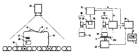
Fig. 3 shows a block diagram of the control and computer architecture of the
picking sys-
tern 1. This comprises the unit load measurement means 19 already generally
disclosed in
Figures 1 and 2, which comprises, in this case, the laser scanner 25 as well
as a measurement
processing module 29 connected thereto, with the help of which the measurement
operation
can be controlled and the data obtained from the laser scanner 25 can be
analyzed and/or
evaluated. The unit load properties a determined by the laser scanner 25 and
the measurement
processing module 29 are written into a data store 31 and stored there for
later use with the
help of the writing means 30 of the measurement processing module 29.
Along the route of the conveying system 9, there may be a monitoring and
classification
unit 32, which is adapted to detect a disruption during the transport of the
unit load 18 and
then classify the transport of the unit load 18 as disrupted or classify the
transport as disrup-
tion-free if no disruption was detected by means of the monitoring and
classification unit 32
during the transport of this unit load 18 within a specifiable observation
period. Specifically,
the monitoring and classification unit 32 comprises multiple sensors 33a, 33b
and a monitor-
ing/classification processing module 34 connected with them. In this example,
the sensor 33a
is specifically configured as a camera; the sensor 33b can be a current
sensor, for example,
which measures the motor current of the motor M. The sensors 33a, 33b capture
the unit
load 18' (which is the unit load 18 at a later point in time) and monitor the
transport of the unit
load 18' together with the monitoring/classification processing module 34.
The transport as such is controlled by means of the control 35, which
transmits, for that pur-
pose, operating parameters b to the conveying system 9. For example, an
operating parame-
ter b can be understood to mean rpm, or an rpm curve, of a motor M.
The unit load properties a from the data store 31 and a transport
classification c determined by
the monitoring and classification unit 32 are fed into a learning algorithm
36. This learning
algorithm 36 can compute a probability of the occurrence of a disruption
during the transport
of the unit loads 18 (in short: "disruption probability" d) from the data
which are received for
a plurality of unit loads 18, depending on the unit load properties a of the
unit loads 18. This
Date recue/Date Received 2022-06-06
CA 03163882 2022-06-06
- 21 -
disruption probability d can be displayed on an output unit 37 or serve as an
input parameter
for the control 35.
Fig. 3 shows the control and computer architecture of the picking system 1
with particular
reference to the learning process of the learning algorithm 36. In contrast,
Fig. 4 represents in
particular how the results of the learning algorithm 36 are used for the
operation of the pick-
ing system 1 during the operating phase.
As soon as the unit load properties a of a unit load 18 are acquired, they are
fed into the learn-
ing algorithm 36 (i.e. not only stored in the data store 31). At that point in
time, it is not
known yet whether this (precise) unit load 18 will cause a disruption during
the transport on
the conveying system 9 because this possible event is in the future. This is
why the arrow
from the monitoring and classification unit 32 to the learning algorithm 36 is
marked with a
dashed line in Fig. 4. However, it is known from the learning phase whether
unit loads 18
with the same or similar properties cause disruptions often or less often.
Accordingly, the
learning algorithm 36 can create a prediction for the unit load 18. This
prediction in the form
of the disruption probability d can be displayed on the output unit 37, or it
is fed into in the
control 35.
In summary, this results in the following procedure, which is visualized also
in Fig. 6 in the
form of a flow chart:
a) determining, with a unit load measurement means 19 of the picking system
1, unit load
properties a of a unit load 18 to be transported with a conveying system 9 of
the picking sys-
tem 1 (step 601),
b) issuing, with an output unit 37 of the picking system 1, a disruption
probability d of
the occurrence of a disruption and/or initiating, with a control 35 of the
picking system 1, a
measure which reduces the probability of the occurrence of this disruption if
the occurrence of
a disruption is probable, based on the respective determined unit load
properties a (step 602),
c) storing the determined unit load properties a in a data store 31
assigned to the unit
load 18 (step 603),
d) transporting the unit load 18 with the conveying system 9 of the picking
sys-
tem 1 (step 604),
Date recue/Date Received 2022-06-06
CA 03163882 2022-06-06
- 22 -
e) monitoring the transport of this unit load 18 by means of a
monitoring and classifica-
tion unit 32 of the picking system 1 and classifying the transport as
disrupted if a disruption
during the transport of this unit load 18 is detected by means of the
monitoring and classifica-
tion unit 32 or classifying as disruption-free the transport by means of the
monitoring and
classification unit 32 if no disruption is detected by means of the monitoring
and classification
unit 32 during the transport of this unit load 18 within a specifiable
observation peri-
od (step 605),
feeding the stored unit load properties a and the transport classification c
of the
transport of the unit load 18 determined in step e) into a learning algorithm
36 (step 606),
repeating steps a) to f) for a plurality of unit loads 18 and computing, with
the help of
the learning algorithm 36, a disruption probability d of the occurrence of a
disruption during
the transport of the different unit loads 18 for which steps a) to f) are run
through, depending
on their unit load properties a (loop 607).
In particular, it is possible, in this procedure, to execute step b) only
after a plurality of run-
throughs of steps a) and c) to f). This means that it is ensured that the
operating phase is pre-
ceded by a sufficiently long learning phase. It is conceivable in particular
that a learning algo-
rithm 36 which has already run through a learning phase is installed in a
picking system 1. In
other words, experiences from other picking systems 1 can be used in a picking
system 1. The
learning phase, therefore, does not start at "zero" but at an expected
behavior of the picking
systems 1. An adaptation to the real conditions prevailing in picking systems
1 can therefore
be done analogously more quickly. Evidently, the learning and operating phases
can also run
in parallel. In relation to a specific unit load 18, one then benefits from
experiences which
were gained during the transport of past unit loads 18 while simultaneously
creating new ex-
periences for future unit loads 18. This is indicated in Fig. 6 with the
dashed arrow, which
symbolizes the retroactive effect of the disruption probability d.
It should also be noted that steps 602 and 603 can also be executed in a
different sequence, or
simultaneously. This similarly applies to steps 604 and 605, which are equally
executed sim-
ultaneously.
Fig. 5 shows another variant of the control and computer architecture of the
picking system 1,
which is similar to the architecture shown in Figs. 3 and 4 but differs from
it with regard to
Date recue/Date Received 2022-06-06
CA 03163882 2022-06-06
- 23 -
the structure of the monitoring and classification unit 32 and the realization
of the data
store 31. In this case, the monitoring and classification unit 32 comprises a
mobile data acqui-
sition unit 38 with a reading means 39, with which an RFID tag 26 and/or a
barcode 27 on a
unit load 18 can be read. It is in particular also conceivable that the
reading means 39 is con-
figured for reading a position mark 24, which is arranged on the conveying
system 9, or at
least assigned to it (see Fig. 1). This position mark 24 can equally be
configured as an RFID
tag or a barcode.
It is conceivable that the data store 31 is contained in the RFID tag 26.
Accordingly, it is also
conceivable that the mobile data acquisition unit 38 detects the unit load
properties a directly.
This is represented in Fig. 5, from which it can also be seen that the unit
load properties a are
transmitted to the learning algorithm 36 by the monitoring and classification
unit 32, in this
case. This means that the unit load properties a assigned to the unit load 18
are read out from
the data store 31 (the RFID tag 26) arranged on the unit load 18, and the unit
load properties a
are transmitted to the learning algorithm 36 together with the transport
classification c.
Yet it is also conceivable that the mobile data acquisition unit 38 detects an
identification e of
the unit load 18, for instance by reading the barcode 27 or the RFID tag 26,
which, in this
embodiment, stores merely an identification e of the unit load 18 but not its
unit load proper-
ties a. In this case, also an identification e arranged on the unit load 18 is
determined, the unit
load properties a assigned to the identification e are read out from the data
store 31 and the
unit load properties a are transmitted to the learning algorithm 36 together
with the transport
classification c.
It should be noted in this context that the identification e of the unit load
18 need not neces-
sarily be determined by means of the mobile data acquisition unit 38, but a
unit load 18 can
also be determined by means of fixed-installation sensors 33a, 33b of the
monitoring and
classification unit 32, in particular by means of the camera 33a. For the sake
of completeness,
it should also be noted that the monitoring and classification unit 32 may
comprise both fixed-
installation sensors 33a, 33b and the mobile data acquisition unit 38.
There is therefore a number of options available for the measure for averting
a disruption ini-
tiated in step b), which options will be enumerated in an exemplary and non-
exhaustive man-
ner below:
Date recue/Date Received 2022-06-06
CA 03163882 2022-06-06
=
=
- 24 -
-) reloading the articles 16c contained in a loading aid 17a into
another loading aid 17b
at a reloading station 20, or initiating such a reloading.
-) taking into account, for the detection of the disruption
probability d, a disruption loca-
tion A at which a disruption occurs and in particular bypassing the predicted
disruption loca-
tion A or changing an operating parameter b of the conveying system 9 at the
predicted dis-
ruption location A.
-) taking into account an operating mode of the conveying system 9 at
the disruption
location A and in particular bypassing the predicted disruption location A or
changing an op-
erating parameter b of the conveying system 9 at the predicted disruption
location A if the
determined operating mode indicates this.
-) taking into account a disruption time which has elapsed up to the
occurrence of a dis-
ruption and/or a disruption path which the unit load 18 traveled up to the
occurrence of a dis-
ruption. In particular, one of the above-mentioned measures can be taken
automatically after
the disruption time has elapsed or after traveling the disruption path, or a
reevaluation of the
unit load 18 by means of the unit load measurement means 19 can be performed.
The measure for averting a disruption initiated in step b) can in particular
be initiated when-
ever the disruption probability d is above a specifiable threshold value. In
this manner, the
level of sensitivity with which the picking system 1 responds to predicted
disruptions can be
controlled. For example, a measure based on the disruption probability d of
the occurrence of
a disruption can be initiated in step b) if said disruption probability d is
above 10%,
above 20% or above a different specifiable value.
In detail, this means the following:
If the unit load 18 is a loading aid 17a loaded with articles 16c, the measure
initiated in step b)
can consist in reloading the articles 16c contained in the (source) loading
aid 17a into anoth-
er (target) loading aid 17b at the reloading station 20 of the picking system
1, or initiating
such a reloading, and subsequently continuing with step a) or transporting the
other (target)
loading aid 17b on the conveying system 9 of the picking system 1 without
running through
steps a) to g).
Date recue/Date Received 2022-06-06
CA 03163882 2022-06-06
- 25 -
This means that the articles 16c contained in the (source) loading aid 17a are
reloaded into
a (target) loading aid 17b for which the occurrence of a disruption is less
probable. If
the (target) loading aid 17b can, a priori, be classified as in order, this
loading aid can be
transported on the conveying system 9 of the picking system 1 without running
through
steps a) to g). If the proper condition of the (target) loading aid 17 cannot
be assumed a priori,
step a) can be carried out next. The reloading of the articles 16c from the
(source) loading
aid 17a onto the (target) loading aid 17b can be done manually or
automatically (as in this
case by means of the reloading robot 22) or combined manually and
automatically.
This operation is easily apparent in Fig. 1. For example, in case of a
disruption probability d
above 20%, it may be provided that the respective unit load 18 is directed, by
means of the
deflection device 23, to the reloading station 20, where the articles 16c are
reloaded as de-
scribed. If the disruption probability d is below that, the unit load 18 is
transported further on
the second storage section 10b (the loop). The deflection device 23 is
therefore configured for
transporting the unit loads 18 directly to the storage zone 8a. .8d or to the
reloading station 20,
depending on the disruption probability d.
It is also conceivable that a disruption location A at which a disruption
occurs is captured by
the monitoring and classification unit 32 in step e), fed into the learning
algorithm 36 in
step f) and taken into account in steps b) and g) in the sense that the
disruption probability d
of the occurrence of a disruption during the transport of the unit loads 18 is
specified depend-
ing on the unit load properties a of a unit load 18 and depending on the
disruption location A.
This ensures that locations in the picking system 1 which are critical for
specific classes of
unit load properties a, i.e. at which disruptions often occur during the
transport of these unit
loads 18, can be identified.
The measure initiated in step b) can in particular consist in transporting the
unit load 18 on the
conveying system 9 of the picking system I whilst bypassing the predicted
disruption location
A, in particular if, or only if, a disruption probability d is smaller as a
result of bypassing the
predicted disruption location A. This option presents itself in particular if
multiple transport
paths are optionally available for the unit load 18 inside the picking system
1. For example, it
may be provided to store the unit load 18 in the storage zone 8a, 8c, 8d, 8e
in which disrup-
tions during the storage operation (and optionally also during the retrieval
operation) are less,
or least, probable. This means that a storing in the storage zone 8b is
avoided because of the
Date recue/Date Received 2022-06-06
CA 03163882 2022-06-06
- 26 -
predicted disruption. It may also be provided that the unit load 18 is
transported to a specific
destination via the transport route for which disruptions during the transport
are less, or least,
probable. For example, the respective unit load 18 can be transported with an
autonomous
guided vehicle 11a..11c if there is danger of a disruption in case of a
transport on the station-
ary conveying system. It is also conceivable that a picking operation in the
picking zone 13
during which the unit load 18 functions as a source loading aid 17d is done at
the manual
picking station 15 if a disruption is probable for an alternative automatic
picking operation at
the automatic picking station 14, and vice versa.
The two above-mentioned variants can also be combined. Provided that the unit
load 18 is a
loading aid 17a loaded with articles 16c, the measure initiated in step b) may
consist in
i) transporting the unit load 18 on the conveying system 9 of the picking
system 1 whilst
bypassing the predicted disruption location A if this is possible or
ii) reloading the articles 16c contained in the loading aid 17a into
another loading aid 17b
at the reloading station 20 of the picking system 1 and subsequently
continuing with step a) or
transporting the other loading aid 17b on the conveying system 9 of the
picking system 1
without running through steps a) to g) if step i) is not possible.
In this variant, a (time-consuming) reloading operation is avoided where
possible, namely
whenever a predicted disruption can be averted by transporting the unit load
18 on the con-
veying system 9 of the picking system 1 whilst bypassing the predicted
disruption location A.
Optionally, step ii) can be executed even if, while step i) is generally
possible, the reduction
of the disruption probability d achievable with it is small, in particular
smaller than the reduc-
tion of the disruption probability d achievable by means of step ii).
It would also be conceivable that the measure initiated in step b) consists in
changing an oper-
ating parameter b of the conveying system 9 at the predicted disruption
location A, in particu-
lar if, or only if, a disruption probability d is lower when changing the
operating parameter b
at the predicted disruption location A. This option presents itself in
particular whenever ad-
justable operating parameters b for the conveying system 9 are available at
the predicted dis-
ruption location A. An operating parameter b is a control variable for
influencing the opera-
tion of the conveying system 9 which is adjustable for the conveying system 9.
An operating
parameter b can be understood to mean, for example, a conveyance speed on the
conveying
system 9 and/or an acceleration on the conveying system 9. For example, it
would be con-
Date recue/Date Received 2022-06-06
CA 03163882 2022-06-06
- 27 -
ceivable to reduce a conveyance speed and/or an acceleration during the
conveyance of the
unit load 18 at the predicted disruption location A.
It would be conceivable, once again, to execute only a conditional reloading
of articles 16c. If
the unit load 18 is a loading aid 17a loaded with articles 16c, for example,
the measure initiat-
ed in step b) may consist in
i) changing an operating parameter b of the conveying system 9 at the
predicted disrup-
tion location A if this is possible or
ii) reloading the articles 16c contained in the loading aid 17a into
another loading aid 17b
(at the reloading station 20 of the picking system 1) and subsequently
continuing with step a)
or transporting the other loading aid 17b on the conveying system 9 of the
picking system 1
without running through steps a) to g) if step i) is not possible.
In this variant, a (time-consuming) reloading operation is equally avoided
where possible,
namely whenever a predicted disruption can be averted by changing an operating
parameter b
of the conveying system 9 at the predicted disruption location A. Optionally,
step ii) can be
executed even if, while step i) is generally possible, the reduction of the
disruption probability
d achievable with it is small, in particular smaller than the reduction of the
disruption proba-
bility d achievable by means of step ii).
Further conceivable would be a combination of the variants for averting a
disruption present-
ed so far. Provided that the unit load 18 is a loading aid 17a loaded with
articles 16c, the
measure initiated in step b) may consist in
i) transporting the unit load 18 on the conveying system 9 of the picking
system 1 whilst
bypassing the predicted disruption location A if this is possible or
ii) changing an operating parameter b of the conveying system 9 at the
predicted disrup-
tion location A if this is possible or
iii) reloading the articles 16c contained in the loading aid 17a into
another loading aid 17b
at the reloading station 20 of the picking system 1 and subsequently
continuing with step a) or
transporting the other loading aid 17b on the conveying system 9 of the
picking system 1
without running through steps a) to g) if step i) or step ii) is not possible.
In this variant, a (time-consuming) reloading operation is avoided, once
again, where possi-
ble, namely whenever a predicted disruption can be averted by transporting the
unit load 18
Date recue/Date Received 2022-06-06
CA 03163882 2022-06-06
=
- 28 -
on the conveying system 9 of the picking system 1 whilst bypassing the
predicted disruption
location A or by changing an operating parameter b of the conveying system 9
at the predict-
ed disruption location A. Optionally, step iii) can be executed even if, while
step i) or step ii)
is generally possible, the reduction of the disruption probability d
achievable with it is small,
in particular smaller than the reduction of the disruption probability d
achievable by means of
step iii). For steps i) and ii), a fixed prioritization (i.e. execute step ii)
only if step i) is not pos-
sible or vice versa) or a prioritization according to the achievable reduction
of the disruption
probability d (i.e. execute the step out of steps i) or ii) for which the
largest reduction of the
disruption probability d is achievable) can be done.
It is advantageous if step 0 is skipped for those unit loads 18 for which the
measure initiated
in step b) consists in transporting the unit load 18 on the conveying system 9
of the picking
system 1 whilst bypassing the predicted disruption location A or for which the
measure initi-
ated in step b) consists in changing an operating parameter b of the conveying
system 9 at the
predicted disruption location A. This prevents the self-learning algorithm 36
from wrongly
assuming that a critical unit load 18 which has caused an active intervention
for avoiding dis-
ruptions is generally uncritical because it does not cause an actual
disruption (which fact,
however, is the result of the active intervention for avoiding disruptions).
For example, the
respective unit loads 18 can be "flagged" and excluded from the learning
process. They will
then be practically non-existent for the self-learning algorithm 36, as is
also the case when
reloading the articles 16c from one loading aid 17a into another loading aid
17b. In this case,
the unit load 18 (expected to be) causing the disruption is discarded (also
physically) and
therefore no longer appears in the further procedure. In addition to step f),
also step e) can be
skipped.
It is further conceivable that an operating mode of the conveying system 9 at
the disruption
location A is acquired in step e), fed into the learning algorithm 36 in step
f) and taken into
account in steps b) and g) in the sense that the disruption probability d of
the occurrence of a
disruption during the transport of the unit loads 18 is specified depending on
the unit load
properties a of a unit load 18, depending on the disruption location A and
depending on the
operating mode at the disruption location A. This ensures that an operating
mode at a disrup-
tion location A which is critical for specific classes of unit load properties
a, i.e. during which
disruptions often occur during the transport of these unit loads 18, can be
identified. An "op-
erating mode" of the conveying system 9 is in particular also the result of
specified operating
Date recue/Date Received 2022-06-06
CA 03163882 2022-06-06
- 29 -
parameters b. For example, values referring to the load of the conveying
system 9, such as
"idle run," "partial-load operation" or "full-load operation," or values
referring to a disrup-
tion, such as "normal operation" or "disrupted operation," may be provided.
Evidently, the
operating mode can also have more detailed characterizing values and in
particular describe a
disruption in more detail. For example, said "operating mode" can be
characterized by or de-
scribe vibrations of a conveying means, for example if a rotating part of the
conveying means
suffered bearing damage. For example, it would be conceivable that light unit
loads 18 drop
statistically more often off a vertical lift whose guide system is no longer
functioning properly
and on which stronger vibrations therefore occur.
It may in particular be provided that a bypassing of the predicted disruption
location A on the
conveying system 9 of the picking system 1 during the transport of the unit
load 18 or a
changing of an operating parameter b of the conveying system 9 at the
predicted disruption
location A is only initiated if a disruption is probable for the operating
mode which is in effect
at the predicted disruption location A. This variant takes into account that
operating modes of
the conveying system 9 can change over time. In particular, this relates to
repair work on the
conveying system 9, after which the operating mode may change abruptly for the
better. For
example, a disruption location A may suddenly be uncritical for specific
classes of unit load
properties a after a repair, whereby an unnecessary rerouting of unit loads 18
or an unneces-
sary intervention into the operating parameters b can be avoided. In
particular, this variant can
also be applied to steps i), ii) and iii) of the above-mentioned embodiments,
wherein the oper-
ating mode at the disruption location A is taken into account here. An example
would be the
repair of the defective guide system of the aforementioned vertical lift,
whereby excessive
vibrations can be avoided in the future. Also light unit loads 18 would then
statistically no
longer inadvertently drop off the vertical lift often (or no longer at all).
In another embodiment variant, a disruption time which elapsed from the point
in time where
the unit load 18 is handed over onto the conveying system 9 (at the goods-in
point 3) up to the
occurrence of a disruption at the disruption location A and/or a disruption
path traveled by the
unit load 18 on the conveying system 9 up to the occurrence of a disruption is
acquired by the
monitoring and classification unit 32 in step e), fed into the learning
algorithm 36 in step f)
and taken into account in steps b) and g) in the sense that the disruption
probability d of the
occurrence of a disruption during the transport of the unit loads 18 is
specified depending on
the unit load properties a of a unit load 18 and depending on the disruption
time and/or the
Date recue/Date Received 2022-06-06
CA 03163882 2022-06-06
=
- 30 -
disruption path. This helps detect whether the occurrence of disruptions
becomes more proba-
ble after a specific residence time of the unit loads 18 on the conveying
system 9 or after trav-
eling a specific path on the conveying system 9 and step b) should therefore
advantageously
be executed. The path mentioned may in particular relate to the distance
traveled (only) or
contain route information also. For example, disruptions are more likely if
the unit load 18
has often passed locations where there is a higher risk of changes in the unit
load properties a
occurring. For example, the passing of infeed and outfeed units could lead to
a disadvanta-
geous deforming of the unit load 18. A time span in which the unit load 18 was
stored in the
store 5 can be taken into account in the above considerations (i.e. in the
simplest case be de-
ducted from the time elapsed between the handover of the unit load 18 onto the
conveying
system 9 up to the occurrence of a disruption), as a substantial change in the
unit load proper-
ties a is not expected in case of mere storing. In particular, this relates to
a deformation of a
unit load 18.
Generally, steps a) to g) can be run through multiple times for one and the
same unit load 18.
This ensures that changes in the unit load properties a which occur over time
are taken into
account. This applies in particular in the above context of the disruption
time and the disrup-
tion path. In that context, it may be provided to run through step a) again as
an alternative to
executing step b), i.e. to detect the unit load properties a again.
It should be noted in this context that, in the structure represented in Fig.
1, a repeated detec-
tion of the unit load properties a is basically only possible with the support
of the autonomous
guided vehicles I1a..11c, or by reversing the first storage section 10a. The
arrangement of the
unit load measurement means 19 at the site represented in Fig. 1 is not
mandatory, however,
but the unit load measurement means 19 can also be arranged at a different
site, for example
in the second storage section 10b. It is also conceivable that multiple unit
load measurement
means 19 are provided along the route of the conveying system 9, in particular
in the region
of the retrieval conveying system 9c.
Further, it should also be noted in this context that there may be conveyors
(not represented in
Fig.1) from the retrieval side to the storage side in the picking system 1, on
which conveyors
loading aids 17a..17g which are no longer needed after the picking operation,
for example,
can be transported to the storage side. Also the autonomous guided vehicles
1la..11c can be
Date recue/Date Received 2022-06-06
CA 03163882 2022-06-06
-31 -
used for this purpose, of course. Accordingly, one and the same loading aid
17a..17g can cir-
culate in the picking system 1 for a relatively long time.
Finally, it is also conceivable that steps b), e), 0 and g) are executed
independent of a disrup-
tion time elapsed from the point in time where the unit load 18 is handed over
onto the con-
veying system 9 up to the occurrence of a disruption and/or independent of a
disruption path
traveled by the unit load 18 on the conveying system 9 up to the occurrence of
a disruption.
Tests have shown that disruptions often occur soon after the handover of a
unit load 18 onto
the conveying system 9 (in this case at the goods-in point 3) and are less
probable to occur
after that. In this variant, the taking into account of the disruption time
and/or of the disrup-
tion path is relinquished in favor of a simplified structure of the learning
algorithm 36.
In summary, the proposed measures ensure that disruptions which are caused by
a unit load
18 on the conveying system 9 of the picking systeml are attributed and/or
assigned to its unit
load properties a. Collecting the respective information for a plurality of
unit loads 18 enables
a "pattern" for the occurrence of disruptions to be identified (provided that
such a pattern ex-
ists). As soon as this knowledge from experience has been gathered,
disruptions can be pre-
dicted and a probability d of their occurrence can be determined and
displayed. Counter-
measures can further be initiated in order to avoid the actual occurrence of
the predicted dis-
ruption. In this manner, in particular negative influences on the picking
system 1 by means of
specific unit loads 18 which were not or could not be taken into account
during the planning
stage of the picking system lcan be identified retrospectively.
Finally, it should be noted that the scope of protection is determined by the
claims. However,
the description and the drawings are to be adduced for construing the claims.
Individual fea-
tures or feature combinations from the different exemplary embodiments shown
and described
may represent independent inventive solutions. The object underlying the
independent in-
ventive solutions may be gathered from the description.
In particular, it should also be noted that, in reality, the depicted devices
can also comprise
more, or also fewer, components than depicted. In some cases, the shown
devices and/or their
components may not be depicted to scale and/or be enlarged and/or reduced in
size.
Date recue/Date Received 2022-06-06
CA 03163882 2022-06-06
- 32 -
List of reference numbers
1 picking system 32 monitoring and classification
2 building unit
3 goods-in point 33a, 33b sensor
4 goods-out point 34 monitoring/classification
article store processing module
35 control
6 storage rack
7 storage and retrieval unit 36 learning algorithm
8a..8e storage zone 37 output unit
9 conveying system 38 mobile data acquisition unit
9a storage conveying system 39 reading means
9b warehouse conveying system
9c retrieval conveying system a property of unit loads
10a..10e storage section b operating parameter
transport classification
11a..11c autonomous guided vehicle d disruption probability
12a..12c retrieval section e identification
13 picking zone
14 automatic picking stations A disruption location
manual picking stations B target shape
indentation
16a..1 6h article(s) D bulge
17a..17g loading aids M motor
18 unit load
19 unit load measurement
means
reloading station
21a supply section
21b discharge section
22 reloading robot
23 deflection device
24 position mark
laser scanner
26 RFID tag
27 barcode
28 conveyor belt
29 measurement processing
module
writing means
31 data store
Date recue/Date Received 2022-06-06