Note: Descriptions are shown in the official language in which they were submitted.
CA 03164238 2022-06-09
WO 2021/133875
PCT/US2020/066780
CIRCULAR ECONOMY FOR PLASTIC WASTE TO POLYETHYLENE VIA
REFINERY CRUDE UNIT
BACKGROUND
[0001] The world has seen extremely rapid growth of plastics production.
According to
PlasticsEurope Market Research Group, the world plastics production was 335
million tons in
2016, 348 million tons in 2017 and 359 million tons in 2018. According to
McKinsey &
Company, the global plastics-waste volume was estimated about 260 million tons
per year in
2016, and projected to be 460 million tons per year by 2030 if the current
trajectory continues.
[0002] Single use plastic waste has become an increasingly important
environmental issue. At
the moment, there appear to be few options for recycling polyethylene and
polypropylene waste
plastics to value-added chemical and fuel products. Currently, only a small
amount of
polyethylene and polypropylene is recycled via chemical recycling, where
recycled and cleaned
polymer pellets are pyrolyzed in a pyrolysis unit to make fuels (naphtha,
diesel), stream cracker
feed or slack wax.
[0003] Processes are known which convert waste plastic into hydrocarbon
lubricants. For
example, U.S. Pat. No. 3,845,157 discloses cracking of waste or virgin
polyolefins to form
gaseous products such as ethylene/olefin copolymers which are further
processed to produce
synthetic hydrocarbon lubricants. U.S. Pat. No. 4,642,401 discloses the
production of liquid
hydrocarbons by heating pulverized polyolefin waste at temperatures of 150-500
C. and
pressures of 20-300 bars. U.S. Pat. No. 5,849,964 discloses a process in which
waste plastic
materials are depolymerized into a volatile phase and a liquid phase. The
volatile phase is
separated into a gaseous phase and a condensate. The liquid phase, the
condensate and the
gaseous phase are refined into liquid fuel components using standard refining
techniques. U.S.
Pat. No. 6,143,940 discloses a procedure for converting waste plastics into
heavy wax
compositions. U.S. Pat. No. 6,150,577 discloses a process of converting waste
plastics into
lubricating oils. EP0620264 discloses a process for producing lubricating oils
from waste or
virgin polyolefins by thermally cracking the waste in a fluidized bed to form
a waxy product,
optionally using a hydrotreatment, then catalytically isomerizing and
fractionating to recover a
lubricating oil.
[0004] Other documents which relate to processes for converting waste plastic
into lubricating
oils include U.S. Patent Nos. 6,288,296; 6,774,272; 6,822,126; 7,834,226;
8,088,961;
1
CA 03164238 2022-06-09
WO 2021/133875
PCT/US2020/066780
8,404,912 and 8,696,994; and U.S. Patent Application Publication Nos.
2019/0161683;
2016/0362609; and 2016/0264885. The foregoing patent documents are
incorporated herein by
reference in their entirety.
[0005] The current method of chemical recycling via pyrolysis cannot make a
big impact for
the plastics industry. The current pyrolysis operation produces poor quality
fuel components
(naphtha and diesel range products), but the quantity is small enough that
these products can be
blended into fuel supplies. However, this simple blending cannot continue if
very large
volumes of waste polyethylene and polypropylene are to be recycled to address
environmental
issues. The products as produced from a pyrolysis unit are of too poor quality
to be blended in
large amounts (for example 5-20 vol% blending) in transportation fuels.
[0006] In order to achieve recycling of single use plastics in an industrially
significant quantity
to reduce its environmental impact, more robust processes are needed. The
improved processes
should establish "circular economy" for the waste polyethylene and
polypropylene plastics
where the spent waste plastics are recycled effectively back as starting
materials for polymers
and high value byproducts.
SUMMARY
[0007] Provided is a continuous process for converting waste plastic into
naphtha for
polyethylene polymerization. The process comprises first selecting waste
plastics containing
polyethylene and/or polypropylene. These waste plastics are then passed
through a pyrolysis
reactor to thermally crack at least a portion of the polyolefin waste and
produce a pyrolyzed
effluent. The pyrolyzed effluent is separated into offgas, a pyrolysis oil and
wax comprising a
naphtha/diesel fraction and a heavy fraction, and char.
[0008] The incorporation of the process with an oil refinery is an important
aspect of the
present process, and allows the creation of a circular economy with a single
use waste plastic
such as polyethylene. Thus, the pyrolysis oil and wax recovered is passed to a
crude unit in a
refinery. A naphtha fraction (C5-C8) is recovered from the distillation
column, and the naphtha
fraction is passed to a steam cracker for ethylene production.
[0009] The refinery will generally have its own hydrocarbon feed flowing
through the refinery
units. The flow volume of pyrolysis oil and wax generated from the pyrolysis
of waste plastic
to the refinery units can comprise any practical or accommodating volume % of
the total flow
to the refinery units. Generally, the flow of the pyrolysis oil and wax
generated from the waste
2
CA 03164238 2022-06-09
WO 2021/133875
PCT/US2020/066780
plastic pyrolysis, for practical reasons, can be up to about 50 vol. % of the
total flow, i.e., the
refinery flow and the pyrolysis flow. In one embodiment, the flow of the
pyrolysis oil and wax
is an amount up to about 20 vol. % of the total flow.
[0010] In another embodiment, a continuous process for converting waste
plastic comprising
polyethylene into a C3-C4 stream for polyethylene polymerization is provided.
The process
comprises selecting waste plastics containing polyethylene and polypropylene.
The selected
waste plastics are passed through a pyrolysis reactor to thermally crack at
least potion of the
polyolefin waste and produce a pyrolyzed effluent. The pyrolyzed effluent is
separated into
offgas, a pyrolyzed oil and wax comprising a naphtha/diesel/heavy fraction,
and char. The
pyrolysis oil and/or optionally wax is passed to a crude unit distillation
column in a refinery. A
portion of a propane and butane (C3-C4) fraction is recovered from the
distillation column, and
then passed to a steam cracker for ethylene production.
[0011] Among other factors, it has been found that by adding refinery
operations one can
upgrade the waste pyrolysis oil and wax to higher value products such as
gasoline, and diesel.
Also, by adding refinery operations it has been found that clean naphtha (C5-
C8) or C3-C4 can
be efficiently and effectively produced from the waste pyrolysis oil and wax
for ultimate
polyethylene polymer production. Positive economics are realized for the
overall process from
recycled plastics to a polyethylene product with product quality identical to
that of virgin
polymer.
BRIEF DESCRIPTION OF THE DRAWINGS
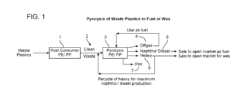
[0012] FIG. 1 depicts the current practice of pyrolyzing waste plastics to
produce fuel or wax
(base case).
[0013] FIG. 2 depicts a present process for establishing a circular economy
for waste plastics.
[0014] FIG. 3 depicts the plastic type classification for waste plastics
recycling.
DETAILED DESCRIPTION
[0015] In the present process, provided is a method to recycle waste
polyethylene and/or
polypropylene back to virgin polyethylene to establish a circular economy by
combining
distinct industrial processes. A substantial portion of polyethylene and
polypropylene polymers
are used in single use plastics and get discarded after its use. The single
use plastic waste has
become an increasingly important environmental issue. At the moment, there
appear to be few
3
CA 03164238 2022-06-09
WO 2021/133875
PCT/US2020/066780
options for recycling polyethylene and polypropylene waste plastics to value-
added chemicals
and fuel products. Currently, only a small amount of
polyethylene/polypropylene is recycled
via chemical recycling, where recycled and cleaned polymer pellets are
pyrolyzed in a
pyrolysis unit to make fuels (naphtha, diesel), steam cracker feed or slack
wax.
[0016] Ethylene is the most produced petrochemical building block. Ethylene is
produced in
hundreds of millions tons per year via steam cracking. The steam crackers use
either gaseous
feedstocks (ethane, propane and/or butane) or liquid feed stocks (naphtha or
gas oil). It is a
noncatalytic cracking process that operates at very high temperatures, up to
850 C.
[0017] Polyethylene is used widely in various consumer and industrial
products. Polyethylene
is the most common plastic, over 100 million tons of polyethylene resins are
produced
annually. Its primary use is in packaging (plastic bags, plastic films,
geomembranes, containers
including bottles, etc.). Polyethylene is produced in three main forms: high-
density
polyethylene (HDPE, 0.940-0.965 g/cm-3), linear low-density polyethylene
(LLDPE, -0.915-
0.940 g/cm-3) and low-density polyethylene (LDPE, (<0.930 g/cm-3), with the
same chemical
formula (C2H4)n but different molecular structure. HDPE has a low degree of
branching with
short side chains while LDPE has a very high degree of branching with long
side
chains. LLDPE is a substantially linear polymer with significant numbers of
short branches,
commonly made by copolymerization of ethylene with short-chain alpha-olefins.
[0018] Low density polyethylene (LDPE) is produced via radical polymerization
at 150 ¨ 300
C and very high pressure of 1,000-3,000 atm. The process uses a small amount
of oxygen
and/or organic peroxide initiator to produce polymer with about 4,000 ¨ 40,000
carbon atoms
per the average polymer molecule, and with many branches. High density
polyethylene
(HDPE) is manufactured at relatively low pressure (10-80 atm) and 80-150 C
temperature in
the presence of a catalyst. Ziegler-Natta organometallic catalysts
(titanium(III) chloride with
an aluminum alkyl) and Phillips-type catalysts (chromium(IV) oxide on silica)
are typically
used, and the manufacturing is done via a slurry process using a loop reactor
or via a gas phase
process with a fluidized bed reactor. Hydrogen is mixed with ethylene to
control the chain
length of the polymer. Manufacturing conditions of linear low-density
polyethylene (LLDPE)
are similar to those of HDPE except copolymerization of ethylene with short-
chain alpha-
olefins (1-butene or 1-hexene).
[0019] Today, only a small portion of spent polyethylene products is collected
for recycling,
due to the inefficiencies and ineffectiveness of the recycling efforts
discussed above.
4
CA 03164238 2022-06-09
WO 2021/133875
PCT/US2020/066780
[0020] FIG. 1 shows a diagram of pyrolysis of waste plastics fuel or wax that
is generally
operated in the industry today. As noted above, generally, polyethylene and
polypropylene
wastes are sorted together 1. The cleaned polyethylene/polypropylene waste 2
is converted in a
pyrolysis unit 3 to offgas 4 and pyrolysis oil (liquid product), and at times
wax. The offgas 4
from the pyrolysis unit is used as fuel to operate the pyrolysis unit 3. An on-
site distillation
unit (not shown) separates the pyrolysis oil to produce naphtha and diesel
products 5 which are
sold to fuel markets. The heavy pyrolysis oil fraction 6 is recycled back to
the pyrolysis unit 3
to maximize the fuel yield. Char 7 is removed from the pyrolysis unit 3. The
heavy fraction 6
is rich in long chain, linear hydrocarbons, and is very waxy (i.e., forms
paraffinic wax upon
cooling to ambient temperature). The wax can be separated from the heavy
fraction 6 and sold
to wax markets.
[0021] The present process converts pyrolyzed polyethylene and/or
polypropylene waste
plastic in large quantities by integrating the waste polymer pyrolysis product
streams into an oil
refinery operation. The resulting processes produce the feedstocks for the
polymers (naphtha
or C3-C4 for ethylene cracker), high quality gasoline and diesel fuel, and/or
quality base oil.
[0022] Generally, the present process provides a circular economy for
polyethylene plants.
Polyethylene is produced via polymerization of pure ethylene. Clean ethylene
can be made
using a steam cracker. Either naphtha or a C3-C4 stream can be fed to the
steam cracker. The
ethylene is then polymerized to create polyethylene.
[0023] By adding refinery operations to upgrade the waste pyrolysis oil and
wax to higher
value products (gasoline and diesel) and to produce clean LPG and naphtha for
steam cracker
for ultimate polyethylene polymer production, one is able to create positive
economics for the
overall process from recycled plastics to polyethylene product with quality
identical to that of
the virgin polymer.
[0024] A pyrolysis unit produces poor quality products containing
contaminants, such as
calcium, magnesium, chlorides, nitrogen, sulfur, dienes, and heavy components,
which
products cannot be used in large quantity for blending in transportation
fuels. It has been
discovered that by having these products go through the refinery units, the
contaminants can be
captured in pre-treating units and their negative impacts diminished. The fuel
components can
be further upgraded with appropriate refinery units with chemical conversion
processes, with
the final transportation fuels produced by the integrated process being of
higher quality and
meeting the fuels quality requirements. The integrated process will generate a
much cleaner
CA 03164238 2022-06-09
WO 2021/133875
PCT/US2020/066780
naphtha stream for stream cracker feedstock for ethylene generation and for
polyethylene
production. These large on-spec productions allow "cyclical economy" for the
recycle plastics
feasible.
[0025] The carbon in and out of the refinery operations are "transparent,"
meaning that all the
molecules from the waste plastic do not necessarily end up in the exact olefin
product cycled
back to the polyolefin plants, but are nevertheless assumed as "credit" as the
net "green" carbon
in and out of the refinery is positive. With the integrated processes, the
amount of virgin feeds
needed for polyethylene plants will be reduced substantially.
[0026] FIG. 2 shows the present integrated process, integrating refinery
operations with recycle
for effective polyethylene production. In FIG. 2, mixed waste plastics are
sorted together 21.
The cleaned waste plastic 22 is converted in a pyrolysis unit 23 to offgas 24
and a pyrolysis oil
(liquid product), and at times a wax (solid product at ambient temperature).
The offgas 24 from
the pyrolysis unit can be used as fuel to operate the pyrolysis unit 23. The
pyrolysis oil is
separated, generally at an on-site distillation unit, into a naphtha/diesel
fraction 25 and a heavy
fraction 26. Char 27 is removed from the pyrolysis unit 23 after completion of
the pyrolysis
step.
[0027] The pyrolysis unit can be located near the waste plastics collection
site, which site could
be away from a refinery, near a refinery, or within a refinery. If the
pyrolysis unit is located
away from the refinery, then pyrolysis product(naphtha/diesel and heavies) can
be transferred
to the refinery by truck, barge, rail car or pipeline. It is preferred,
however, that the pyrolysis
unit is within the plastics collection site or the refinery.
[0028] The preferred starting material for the present process is sorted waste
plastics
containing predominantly polyethylene and polypropylene (plastics recycle
classification types
2, 4, and 5). The pre-sorted waste plastics are washed and shredded or
pelleted to feed to a
pyrolysis unit for thermal cracking. FIG. 3 depicts the plastic type
classification for waste
plastics recycling. Classification types 2, 4, and 5 are high density
polyethylene, low density
polyethylene and polypropylene, respectively. Any combination of the
polyethylene and
polypropylene waste plastics can be used. For the present process, at least
some polyethylene
waste plastic is preferred.
[0029] Proper sorting of waste plastics is very important in order to minimize
contaminants
such as N, Cl, and S. Plastics waste containing polyethylene terephthalate
(plastics recycle
classification type 1), polyvinyl chloride (plastics recycle classification
type 3) and other
6
CA 03164238 2022-06-09
WO 2021/133875
PCT/US2020/066780
polymers (plastics recycle classification type 7) need to be sorted out to
less than 5%,
preferably less than 1% and most preferably less than 0.1%. The present
process can tolerate a
moderate amount of polystyrene (plastics recycle classification type 6). Waste
polystyrene
needs to be sorted out to less than 30%, preferably less than 20% and most
preferably less than
5%.
[0030] Washing of waste plastics removes contaminants such as sodium, calcium,
magnesium,
aluminum, and non-metal contaminants coming from other waste sources. Non-
metal
contaminants include contaminants coming from the Periodic Table Group IV,
such as silica,
contaminants from Group V, such as phosphorus and nitrogen compounds,
contaminants from
Group VI, such as sulfur compounds, and halide contaminants from Group VII,
such as
fluoride, chloride and iodide. The residual metals, non-metal contaminants,
and halides need to
be removed to less than 50 ppm, preferentially less than 30 ppm and most
preferentially to less
than 5 ppm.
[0031] If the washing does not remove the metals, non-metal contaminants, and
halide
impurities adequately, then a separate guard bed can be used to remove the
metals and non-
metal contaminants.
[0032] The pyrolyzing is carried out by contacting a plastic material
feedstock in a pyrolysis
zone at pyrolysis conditions, where at least a portion of the feed(s) is
cracked, thus forming a
pyrolysis zone effluent comprising olefins and n-paraffins. Pyrolysis
conditions include a
temperature of from about 400 C. to about 700 C., preferably from about 450
C. to about
650 C. Conventional pyrolysis technology teaches operating conditions of
above-atmospheric
pressures. See e.g., U.S. Pat. No. 4,642,401. Additionally, it has been
discovered that by
adjusting the pressure downward, the yield of a desired product can be
controlled. See, e.g.,
U.S. Pat. No. 6,150,577. Accordingly, in some embodiments where such control
is desired, the
pyrolysis pressure is sub-atmospheric.
[0033] FIG. 2 shows the present integrated process where the entire pyrolysis
oil and wax from
the pyrolysis unit is sent to a refinery crude unit desalter 28. The crude
unit desalter eliminates
any contaminants in the pyrolysis product, then the product is sent to a crude
unit distillation
column (not shown as part of the refinery crude unit). Alternatively, the
pyrolysis oil and wax
can be treated at the pyrolysis site to remove the contaminants, and then
injected directly to the
refinery crude distillation unit.
7
CA 03164238 2022-06-09
WO 2021/133875
PCT/US2020/066780
[0034] The refinery crude unit separates crude oil into multiple fractions
such as liquefied
petroleum gas (LPG), naphtha, kerosene, diesel and gas oil which will be
further treated into
useful petroleum products. The refinery crude unit has a crude treating
section, commonly
known as a desalter, and a crude oil distillation or fractionation section.
The distillation section
typically includes an atmospheric distillation unit and a vacuum distillation
unit.
[0035] The pyrolysis oil (and wax) is fed to the desalter which removes the
salts and solids
contained in the oil to protect downstream equipment from the harmful effects
of the
contaminants. To remove the salts, water is mixed with the oil and typically
heated to
temperatures between about 215 F to about 280 F and allowed to separate in
the desalter unit.
[0036] The refinery will generally have its own hydrocarbon feed flowing
through the refinery
units. The flow volume of pyrolysis oil and wax generated from the pyrolysis
of waste plastic
to the refinery units can comprise any practical or accommodating volume % of
the total flow
to the refinery units. Generally, the flow of the pyrolysis oil and wax
generated from the waste
plastic pyrolysis, for practical reasons, can be up to about 50 vol. % of the
total flow, i.e., the
refinery flow and the pyrolysis flow. In one embodiment, the flow of the
pyrolysis oil and wax
is an amount up to about 20 vol. % of the total flow. In another embodiment,
the flow of the
pyrolysis oil and wax is an amount up to about 10 vol. % of the total flow.
About 20 vol. % has
been found to be an amount that is quite practical in its impact on the
refinery while also
providing excellent results and being an amount that can be accommodated. The
amount of
pyrolysis oil and wax generated from the pyrolysis can of course be controlled
so that the
fraction passed to the refinery units provide the desired volume % of the
flow.
[0037] Desalted oil and wax is sent to an atmospheric distillation unit heated
to about 340-372
C (644-700 F) at the bottom of the distillation column, and liquid is removed
at various points
of the fractional distillation column to produce various fuels. The fuels from
the crude units
can be sent to various upgrading units in the refinery to remove impurities
(nitrogen, sulfur)
and to catalytically transform the fractions to improve the product
properties, such as octane
and cetane numbers. The bottom residue from the atmospheric distillation
column, also known
as atmospheric residue, is typically sent to a vacuum distillation column to
produce vacuum gas
oil (650 ¨ 1050 F) and vacuum residue. The vacuum gas oil may be used to
produce lube oil
or further cracked to produce gasoline, jet and diesel fuel. The overall
process can produce
LPG (<80 F), gasoline (80-400 F), jet fuel (360-500 F), and diesel fuel
(300-700 F). The
boiling points for these fractions are adjusted depending on the season and
local specifications.
8
CA 03164238 2022-06-09
WO 2021/133875
PCT/US2020/066780
[0038] From the refinery crude distillation unit, a C5-C8 naphtha stream 29,
preferentially a C5-
C7 naphtha and most preferentially a C5-C6 naphtha stream is collected. The
light naphtha
stream is rich in linear paraffins and is a very good light naphtha feed for a
steam cracker 30 to
generate ethylene. The ethylene is passed on to a polymerization unit 40 to
produce
polyethylene. The polyethylene is processed further to produce various
polyethylene products
41 to fit the needs of consumer products. The heavy portion of the pyrolysis
oil can be
combined with hydrocarbon from the crude unit distillation and sent to
appropriate refinery
units as a heavy naphtha, diesel, atmospheric gas oil stream 31 for upgrading
into clean
gasoline, diesel, or jet fuel.
[0039] The ethylene polymerization unit is preferably located near the
refinery so that the
feedstocks (propane, butane, naphtha) can be transferred via pipeline. For a
petrochemical
plant located away from the refinery, the feedstock can be delivered via
truck, barge, rail car or
pipeline.
[0040] In another embodiment, a C3-C4 fraction 32 is recovered from the
refinery crude unit
28. This stream can also be fed to the steam cracker 30 for the production of
ethylene. The
ethylene is passed on to a polymerization unit 40 to produce polyethylene. The
polyethylene is
processed further to produce various polyethylene products 41 to fit the needs
of consumer
products.
[0041] The benefits of a circular economy and an effective and efficient
recycling campaign
are realized by the present integrated process.
[0042] The following examples are provided to further illustrate the present
process and its
benefits. The examples are meant to be illustrative and not limiting.
[0043] Example 1: Properties of Pyrolysis Oil and Wax From Commercial Sources
[0044] Pyrolysis oil and wax samples were obtained from commercial sources and
their
properties are summarized in Table 1. These pyrolysis samples were prepared
from waste
plastics containing mostly polyethylene and polypropylene via thermal
decomposition in a
pyrolysis reactor at around 400-600 C, near atmospheric pressure without any
added gas or a
catalyst. A pyrolysis unit typically produces gas, liquid oil product,
optionally wax product,
and char. The pyrolysis unit's overhead gas stream containing thermally
cracked hydrocarbon
was cooled to collect condensate as pyrolysis oil (liquid at ambient
temperature) and/or
pyrolysis wax (solid at ambient temperature). The pyrolysis oil is the main
product of the
9
CA 03164238 2022-06-09
WO 2021/133875 PCT/US2020/066780
pyrolysis units. Some units produce pyrolysis wax as a separate product in
addition to the
pyrolysis oil.
Table 1
Properties of As-Received Oil and Wax from Pyrolysis of Waste Plastics
Pyrolysis Oil Pyrolysis Oil Pyrolysis Oil
Pyrolysis Oil Pyrolysis Wax
Sample A Sample B Sample C Sample D Sample E
Specific Gravity at 60 F 0.814 0.820 0.774 - 0.828
Simulated Distillation, F
0.5% (Initial Boiling Point) 87 299 18 86 325
5% 179 306 129 154 475
10% 214 309 156 210 545
30% 322 346 285 304 656
50% 421 447 392 421 733
70% 545 585 517 532 798
90% 696 798 663 676 894
95% 772 883 735 743 939
99.5% (Final Boiling Point) 942 1079 951 888 1064
Carlo-Elba Hydrocathon Analysis
Catbon, wt% 87.6 84.21 85.46 85.97 85.94
Hydrogen, wt% 12.7 12.25 14.1 14.0 14.15
Sum of C + H, wt% 100.3 96.46 99.5 100.0 100.1
H/C Molar Ratio 1.73 1.75 1.98 1.96 1.98
Bromine Number, g/ 100 g 49 60 40 44 14
Hydrocathon Type
Total Aromatics, vol% 23.3 22.8 5.1 8.7 13.3
Total Olefins & Naphthenes, vol% 39.0 50.2 42.4 38.2
42.1
Total Paraffins, vol% 37.7 27 52.5 53.1 44.6
Contaminants
Total S, ppm 48 29 7.8 99 6.3
Total N, ppm 751 1410 318 353 237
Total Cl, ppm 113 62 41 70 4.7
0 in naphtha & distillate, ppm 250 - 574 -
Trace Elemental Impurities
Al, PP111 <1.1 <0.56 0.6 <0.53 <0.68
Ca, ppm 1.4 11.5 <0.5 <0.53 <0.68
Fe, ppm 4.9 11.9 1.6 <1.1 3.1
Mg, ppm <0.51 1.3 <0.52 <0.53 <0.68
Na, ppm 2.5 <0.54 <1.1 <2.2 <2.7
Ni, ppm <0.51 <0.54 <0.52 2 <0.68
V, ppm <0.51 <0.54 <0.52 4 <0.68
13, PM 8.2 9.9 <1.6 <2.2 20.2
Si, ppm 82.5 49.6 13 17 3.1
[0045] ASTM D4052 method was used for specific gravity measurements. Simulated
boiling
point distribution curve was obtained using ASTM D2887 method. Carlo-Erba
analysis for
carbon and hydrogen was based on ASTM D5291 method. Bromine number measurement
was
based on ASTM D1159 method. Hydrocarbon-type analysis was done using a high
resolution
magnetic mass spectrometer using the magnet scanned from 40 to 500 Daltons.
Total sulfur
was determined using XRF per ASTM D2622 method. The nitrogen was determined
using a
modified ASTM D5762 method using chemiluminescence detection. The total
chloride
content was measured using combustion ion chromatography instrument using
modified ASTM
CA 03164238 2022-06-09
WO 2021/133875
PCT/US2020/066780
7359 method. The oxygen content in naphtha and distillate boiling range was
estimated using
GC by GC/MS measurements with electron ionization detector for m/Z range of 29-
500. Trace
metal and non-metal elements in oil were determined using inductively coupled
plasma-atomic
emission spectrometry (ICP-AES).
[0046] Industrial pyrolysis process of sorted plastics, sourced predominantly
from polyethylene
and polypropylene waste, produced quality hydrocarbon streams with specific
gravity ranging
0.7 to 0.9, and a boiling range from 18 to 1100 F as in pyrolysis oil or
pyrolysis wax.
[0047] The pyrolysis product is rather pure hydrocarbon made of mostly carbon
and hydrogen.
The hydrogen to carbon molar ratio varies from 1.7 to near 2Ø The Bromine
Number is in the
range of 14 through 60 indicating varying degrees of unsaturation coming from
olefins and
aromatics. The aromatic content is in the range of 5 to 23 volume % with a
higher severity unit
producing more aromatics. Depending on the process conditions of the pyrolysis
unit, the
pyrolysis products show paraffinic content ranging from mid-20 vol. % to mid-
50 vol. %. The
pyrolysis product contains a substantial amount of olefins. Samples A and B,
pyrolysis oil
produced under more severe conditions such as higher pyrolysis temperature
and/or longer
residence time, contain higher aromatic and lower paraffinic components,
resulting H/C molar
ratio of around 1.7 and high Bromine Number of 50-60. Samples C and D were
produced at
less severe conditions, and the pyrolysis oils are more paraffinic, resulting
H/C molar ratio of
close to 2.0 and Bromine Number around 40. Sample E, pyrolysis wax, is mostly
paraffinic,
saturated hydrocarbon with a substantial amount of normal hydrocarbons (as
opposed to
branched hydrocarbons) with low Bromine Number of only 14.
[0048] The following Examples 2 through 5 show the evaluation of waste
plastics pyrolysis oil
for transportation fuel.
[0049] Example 2: Fractionation of Pyrolysis Oil for Evaluation As
Transportation Fuel
[0050] Sample D was distilled to produce hydrocarbon cuts representing
gasoline (350 F-), jet
(350 ¨ 572 F), diesel (572 ¨ 700 F) and the heavy (700 F+) fractions. Table
2 summarizes
the boiling point distribution and impurity distributions among the distilled
product fractions.
11
CA 03164238 2022-06-09
WO 2021/133875
PCT/US2020/066780
Table 2
Distillation of Pyrolysis Oil into Fuel Fractions
Sample ID Sample D Sample F . Sample G Sample
H Sample I
Intended Fraction Gasoline Cut Jet Cut Diesel Cut
Unconverted
Cut Point Target, F 350- . 350-572 572-700 700+
Distillation Actual Yields, wt% 37.2 38.0 15.0 9.3
Simulated Distillation, F
IBP (0.5 wt%) 86 27 299 539 640
wt% 154 98 345 557 684
wt% 210 147 365 574 696
30 wt% 304 222 416 597 727
50 wt% 421 270 457 619 758
70 wt% 532 291 492 644 808
90 wt% 676 337 546 674 898
95 wt% 743 347 554 683 953
FBP (99.5 wt%) 888 385 591 711 1140
Total S, ppm 99 52 35 80 320
Total N, ppm 353 215 556 232 467
Total Cl, ppm 70 181 27 12 13
[0051] Example 3: Evaluation of Pyrolysis Oil Cut for Gasoline Fuel
[0052] Sample F, a pyrolysis oil cut for gasoline fuel boiling range, was
evaluated to assess its
potential to use as gasoline fuel. Sample F has the carbon number range of C5
¨ C12, typical
of the gasoline fuel.
[0053] Due to the olefinic nature of the pyrolysis oil, oxidation stability
(ASTM D525) and
gum forming tendency (ASTM D381) were identified as the most critical
properties to
examine. Research octane number (RON) and motor octane number (MON) are also
the
critical properties for engine performance. The RON and MON values were
estimated from
detailed hydrocarbon GC analysis.
Table 3
Evaluation of Pyrolysis Oil Naphtha Fraction for Gasoline Fuel
Oxidation Washed Gum, RON MON
Stability, mm mg/100 ml,
Sample F 90 5.0 71.4 67.7
Reference gasoline >1440 1 95.8 86.2
4/96 vol.% Blend of Sample F with >1440 2.0 94.5 85.1
reference gasoline
15/85 vol.% Blend of Sample F with >1440 2.2 91.8 83.1
reference gasoline
[0054] Sample F, a pyrolysis oil cut for gasoline fuel boiling range, cannot
be used by itself as
automotive gasoline fuel due to its poor quality. The gasoline fraction from
the pyrolysis oil
12
CA 03164238 2022-06-09
WO 2021/133875
PCT/US2020/066780
showed very poor oxidation stability in that Sample F failed only after 90 min
compared to the
target stability of longer than 1440 minutes. The pyrolysis gasoline exceeded
the wash gum
target of 4 mg/ 100 mL suggesting severe gum forming tendency. The pyrolysis
gasoline has
poor octane numbers compared to the reference gasoline. A premium unleaded
gasoline was
used as the reference gasoline.
[0055] We also examined the potential of blending of the pyrolysis gasoline
cut for a limited
amount to the reference gasoline. Our study showed that possibly up to 15
volume % of
Sample F can be blended to the refinery gasoline while still meeting the fuels
property targets.
By integrating the pyrolysis gasoline product with a refinery fuel, the
overall product quality
can be maintained.
[0056] These results indicate that the as-produced gasoline fraction of
pyrolysis oil has limited
utility as gasoline fuel. Upgrading in a refinery unit is preferred to convert
this gasoline
fraction of the pyrolysis oil into hydrocarbon that meets the gasoline fuel
property targets.
[0057] Example 4: Evaluation of Pyrolysis Oil Cut for Jet Fuel
[0058] Sample G, a pyrolysis oil cut for jet fuel boiling range, was evaluated
to assess its
potential to use as jet fuel. Sample G has the carbon number range of C9 ¨
C18, typical of the
jet fuel.
[0059] Due to the olefinic nature of the pyrolysis oil, jet fuel thermal
oxidation test (D3241)
was considered as the most critical test. The pyrolysis oil jet cut as-is,
Sample G, had only 36
minutes of oxidation stability suggesting the pure pyrolysis jet cut is
unsuitable for use as jet
fuel.
[0060] We prepared a 5 volume % blend of pyrolysis jet cut (Sample G) with
refinery
produced jet. The blend still failed for the jet fuel oxidation test as shown
in Table 4.
Table 4
Evaluation of Pyrolysis Oil Jet Fraction for Jet Fuel
Jet Fuel Thermal Oxidation Test
Reference jet fuel Passed
5/95 vol.% Blend of Sample G with reference jet fuel Failed
[0061] These results indicate that the as-produced jet fraction of pyrolysis
oil is completely
unsuitable for jet fuel, and upgrading in a refinery unit is required to
convert this jet fraction of
the pyrolysis oil into hydrocarbon that meets the jet fuel property targets.
[0062] Example 5: Evaluation of Pyrolysis Oil Cut for Diesel Fuel
13
CA 03164238 2022-06-09
WO 2021/133875
PCT/US2020/066780
[0063] Sample H, a pyrolysis oil cut for diesel fuel boiling range, was
evaluated to assess its
potential to use as diesel fuel. Sample H has the carbon number range of C14 ¨
C24, typical of
the diesel fuel.
[0064] Sample H contains a substantial amount of normal hydrocarbons. Since
normal
hydrocarbons tends to exhibit waxy characteristics, cold flow properties such
as pour point
(ASTM D5950-14) and cloud points (ASTM D5773) were considered as the most
critical tests.
[0065] We prepared two blends at 10 and 20 volume % of Sample H with refinery
produced
diesel fuel. However, both blends still failed for the target pour point of
less than -17.8 C (0
F) pour points.
Table 5
Evaluation of Pyrolysis Oil Diesel Fraction for Diesel Fuel
Cloud Point ( C) Pour Point ( C) Pour Point Test
Reference diesel fuel -17.1 -19.0 Passed
10/90 vol.% Blend of Sample H with -11.1 -12.0 Failed
reference diesel fuel
20/80 vol.% Blend of Sample H with -5.5 -7.0 Failed
reference diesel fuel
[0066] These results indicate that the pyrolysis oil as-is is completely
unsuitable for diesel fuel,
and upgrading in a refinery unit is required to covert the diesel fraction of
pyrolysis oil into
hydrocarbon that meets the diesel fuel property targets.
[0067] Examples 6: Coprocessing of Pyrolysis Product to Crude Unit or Desalter
Unit
[0068] Results from Table 1 showed that industrial pyrolysis process of sorted
plastics, sourced
predominantly from polyethylene and polypropylene waste, produced quality
pyrolysis oil or
pyrolysis wax made of mostly carbon and hydrogen. With good sorting and
efficient pyrolysis
unit operation, the nitrogen and sulfur impurities are at low enough levels
that a modem
refinery can handle cofeeding of pyrolysis feedstocks to their processing
units with no
detrimental impacts.
[0069] However, some pyrolysis oils or wax may still contain high amounts of
metals (Ca, Fe,
Mg) and other non-metals (P, Si, Cl, 0) that could negatively affect the
performance of
conversion units in a refinery. For pyrolysis products with high impurity
levels are
preferentially fed to a desalter unit before by the crude unit so that bulk of
impurities are
removed effectively by the desalter.
[0070] By feeding the entire pyrolysis feedstock to a crude unit or to a
desalter unit before the
crude unit, the pyrolysis oil and wax will be fractionated into multiple
components and then
14
CA 03164238 2022-06-09
WO 2021/133875
PCT/US2020/066780
converted in the subsequent conversion units including paraffin isomerization
unit, jet
hydrotreating unit, diesel hydrotreating unit, fluid catalytic cracking unit
(FCC), alkylation unit,
hydrocracking unit and/or coker unit to make gasoline, jet and diesel fuel
with satisfactory
product properties. The conversion units (FCC or hydrocracking unit) will also
convert the
heavy cut (corresponding to Sample I) or wax (Sample E) into quality
transportation fuels.
[0071] After the crude unit, the pyrolysis oil and wax will be converted
further in the
subsequent conversion units. The following Examples 7 and 8 demonstrate the
conversion of
waste plastics pyrolysis product into quality transportation fuel in a
refinery conversion unit,
using a FCC unit as an example.
[0072] Example 7: Conversion of Pyrolysis Oil in FCC
[0073] To study the impact of coprocessing of waste plastics pyrolysis oil to
FCC, series of
laboratory tests were carried out with Samples A and C. Vacuum gas oil (VGO)
is the typical
feed for FCC. FCC performances of 20% blend of pyrolysis oil with VGO and pure
pyrolysis
oil were compared with that of the pure VGO feed.
[0074] The FCC experiments were carried out on a Model C ACE (advanced
cracking
evaluation) unit fabricated by Kayser Technology Inc. using regenerated
equilibrium catalyst
(Ecat) from a refinery. The reactor was a fixed fluidized reactor using N2 as
fluidization gas.
Catalytic cracking experiments were carried out at the atmospheric pressure
and 900 F reactor
temperature. The cat/oil ratio was varied between 5 to 8 by varying the amount
of the catalyst.
A gas product was collected and analyzed using a refinery gas analyzer (RGA),
equipped with
GC with FID detector. In-situ regeneration of a spent catalyst was carried out
in the presence
of air at 1300 F, and the regeneration flue gas was passed through a LECO
unit to determine
the coke yield. A liquid product was weighted and analyzed in a GC for
simulated distillation
(D2887) and C5- composition analysis. With a material balance, the yields of
coke, dry gas
components, LPG components, gasoline (C5-430 F), light cycle oil (LCO, 430-
650 F) and
heavy cycle oil (HCO, 650 F) were determined. The results are summarized below
in Table 6.
Table 6
Evaluation of Pyrolysis Oil Cofeeding to FCC
Feed 100% VGO 20/80 vol% blend, 20/80 vol% blend,
100% 100%
Sample A/ VGO Sample Cl VGO Sample A Sample C
Cat/Oil, wt/wt 6.0 6.0 6.0 6.0 6.0
Conversion, wt%* 81.3 83.15 83.09 76.1 78.82
WLP Impurity**
Total 0, ppm 81 76 62 54 67
Total N, ppm 27 30 33 50 21
Yields
CA 03164238 2022-06-09
WO 2021/133875
PCT/US2020/066780
Coke, wt% 4.45 4.35 4.20 3.56 2.90
Total Dry Gas, wt% 2.08 1.96 1.93 1.55 1.43
Hydrogen 0.16 0.12 0.12 0.05 0.04
Methane 0.68 0.65 0.64 0.50 0.46
Ethane 0.44 0.43 0.41 0.33 0.28
Ethylene 0.76 0.74 0.72 0.63 0.61
Total LPG, wt% 21.25 21.08 21.50 20.17 24.40
Propane 1.78 1.76 1.72 1.47 1.53
Propylene 5.53 5.51 5.56 5.57 6.75
n-Butane 1.56 1.56 1.54 1.29 1.34
Isobutane 6.61 6.48 6.64 5.43 6.61
C4 olefins 5.77 5.77 6.04 6.41 8.16
Gasoline, wt% 53.53 55.75 55.46 62.53 61.75
LCO, wt% 12.89 12.23 11.93 10.37 8.03
HCO, wt% 5.81 4.63 4.98 1.82 1.50
Octane Number*** 88.05 84.57 82.79 73.75 75.41
*: Conversion - conversion of 430 F+ fraction to 430 F-
**: Impurity level of N and 0 in whole liquid product in fuels boiling range
by GC x GC, ppm
***: Octane number, (R+M)/2, was estimated from detailed hydrocarbon GC of FCC
gasoline.
[0075] The results in Table 6 show that up to 20 volume % cofeeding of
pyrolysis oil only
makes very slight changes in the FCC unit performance indicating coprocessing
of pyrolysis oil
up to 20% is readily feasible. The 20 volume % blending of Sample A or Sample
C led to very
slight reduction of coke and dry gas yields, slight increase in gasoline yield
and slight decrease
in LCO and HCO, which are favorable in most situations. With paraffinic nature
of pyrolysis
oil, the 20% blends of A and C lowered the Octane number by about 3-5 numbers.
With
refinery operational flexibility, these octane number debits can be
compensated with blending
or feeding location adjustments. By cofeeding the pyrolysis oil through the
FCC process unit
with a zeolite catalyst, the oxygen and nitrogen impurities in the fuel range
were reduced
substantially, from about 300-1400 ppm N to about 30 ppm N and from about 250-
540 ppm 0
to about 60-80 ppm 0. The hydrocarbon composition of all these cofeeding
products are well
within the typical FCC gasoline range.
[0076] The FCC runs of 100% pyrolysis oil showed substantial debits of Octane
numbers by
about 13-14 numbers. This shows that coprocessing of pyrolysis oil is
preferred over
processing of pure 100% pyrolysis oil.
[0077] Example 8: Coprocessing of Pyrolysis Wax in FCC
[0078] To study the impact of coprocessing of waste plastics pyrolysis wax to
FCC, series of
laboratory tests were carried out with Sample E and VGO. FCC performances of
20% blend of
pyrolysis wax with VGO and pure pyrolysis wax were compared with that of the
pure VGO
feed, similar to Example 7. The results are summarized below in Table 7.
16
CA 03164238 2022-06-09
WO 2021/133875
PCT/US2020/066780
Table 7
Evaluation of Pyrolysis Wax Cofeeding to FCC
Feed 100% VGO 20/80 vol% blend, 100%
Sample E/ VGO Sample E
Cat/Oil, wt/wt 6.5 6.5 6.5
Conversion, wt%* 82.75 84.17 91.31
Yields
Coke, wt% 4.78 4.76 4.26
Total Diy Gas, wt% 2.11 2.05 1.79
Hydrogen 0.16 0.14 0.07
Methane 0.69 0.67 0.58
Ethane 0.44 0.43 0.37
Ethylene 0.78 0.77 0.73
Total LPG, wt% 21.71 23.15 31.79
Propane 1.87 1.93 2.28
Propylene 5.54 5.98 8.59
n-Butane 1.65 1.74 2.15
Isobutane 6.91 7.25 8.88
C4 olefins 5.74 6.25 9.89
Gasoline, wt% 54.16 54.21 53.47
LCO, wt% 12.42 11.59 6.71
HCO, wt% 4.83 4.24 1.99
Octane Number** 89.95 88.38 83.52
*: Conversion - conversion of 430 F+ fraction to 430 F-
**: Octane number, (R+M)/2, was estimated from detailed hydrocarbon GC of FCC
gasoline.
[0079] The results in Table 7 shows that up to 20 volume % cofeeding of
pyrolysis wax only
makes very slight changes in the FCC unit performance indicating coprocessing
of pyrolysis
wax up to 20% is readily feasible. The 20 volume % blending of Sample E led to
very slight
reduction to no change of coke and dry gas yields, noticeable increase in LPG
olefin yield, very
slight increase in gasoline yield and slight decrease in LCO and HCO, which
are all favorable
in most situations. With paraffinic nature of pyrolysis wax, the 20% blend of
Sample E
lowered the Octane number slightly by 1.5 number. With refinery blending
flexibility, this
octane number debit can be easily compensated with minor blending adjustments.
[0080] The FCC run of 100% pyrolysis wax showed substantial increase in
conversion, and
debit of the Octane number by 6. This shows that coprocessing of pyrolysis wax
is preferred
over processing of 100% pyrolysis wax.
[0081] Example 9: Feedstocks of C3-C4 and/or Naphtha Generation from Waste
Plastics
Pyrolysis Product Cofeeding to Refinery Crude Unit
[0082] By feeding of the entire pyrolysis feedstock to a crude unit or to a
desalter unit before
the crude unit, the pyrolysis oil and wax will be fractionated into multiple
components. With
the pyrolysis oil cofeeding, the refinery crude unit produces a substantial
amounts of clean
propane, butane, and naphtha streams, as well as other streams for refinery
conversion units.
17
CA 03164238 2022-06-09
WO 2021/133875
PCT/US2020/066780
[0083] Example 10: Feeding of Recycle C3-C4 and/or Naphtha to Steam Cracker
for
Ethylene Production, Followed by Productions of Polyethylene Resin and
Polyethylene
Consumer Products
[0084] The propane, butane and naphtha streams, produced via cofeeding of
pyrolysis products
to a crude unit per Example 9, are good feedstocks to cofeed to a steam
cracker for production
of ethylene with a recycle content. At least a portion of the streams, if not
all, are fed to the
steam cracker. The ethylene is processed to a polymerization unit to produce
polyethylene
resin containing some recycled-polyethylene/ polypropylene derived materials
while the quality
of the newly produced polyethylene is indistinguishable to the virgin
polyethylene made
entirely from virgin petroleum resources. The polyethylene resin with the
recycled material is
then further processed to produce various polyethylene products to fit the
needs of consumer
products. These polyethylene consumer products now contains chemically
recycled, circular
polymer while quality of the polyethylene consumer products are
indistinguishable from those
made entirely from virgin polyethylene polymer. These chemically recycled
polymer products
are different from the mechanically recycled polymer products whose qualities
are inferior to
the polymer products made from virgin polymers.
[0085] As used in this disclosure the word "comprises" or "comprising" is
intended as an open-
ended transition meaning the inclusion of the named elements, but not
necessarily excluding
other unnamed elements. The phrase "consists essentially of' or "consisting
essentially of' is
intended to mean the exclusion of other elements of any essential significance
to the
composition. The phrase "consisting of' or "consists of' is intended as a
transition meaning
the exclusion of all but the recited elements with the exception of only minor
traces of
impurities.
[0086] All patents and publications referenced herein are hereby incorporated
by reference to
the extent not inconsistent herewith. It will be understood that certain of
the above-described
structures, functions, and operations of the above-described embodiments are
not necessary to
practice the present invention and are included in the description simply for
completeness of an
exemplary embodiment or embodiments. In addition, it will be understood that
specific
structures, functions, and operations set forth in the above-described
referenced patents and
publications can be practiced in conjunction with the present invention, but
they are not
essential to its practice. It is therefore to be understood that the invention
may be practiced
otherwise that as specifically described without actually departing from the
spirit and scope of
the present invention as defined by the appended claims.
18