Note: Descriptions are shown in the official language in which they were submitted.
CA 03164816 2022-06-14
WO 2021/125949
PCT/NL2020/050793
Feeding system and method for feeding animals
The invention relates to a feeding system for feeding animals, in particular
cows, such as dairy cows or meat cows.
EP 2134161 Al discloses an automatic feeding system for animals. The
feeding system comprises a mixing device, a control device, a plurality of
feeding areas
and a feed measurement arrangement. The animals are usually divided into
groups, for
example based on the lactation stage or milk yield, with each group having a
different
feed requirement. Each group of animals has access to one of the feeding
areas. The
control device controls the mixing device in order to prepare a batch of feed
according to
a selected recipe. The batch of mixed feed is accommodated in an automatic
feeding
device which takes the batch of mixed feed to the feeding areas, so that the
animals are
able to eat from it. The feed measurement arrangement repeatedly measures the
quantity
of mixed feed which is present at the feeding areas. The control device
repeatedly
compares the measured remaining quantity of mixed feed in the feeding areas
with a
threshold value. The threshold value can be set separately for each feeding
area, for
example by a farmer. If the measured remaining quantity of mixed feed in one
of the
feeding areas falls below the threshold value, the control device sends a
command to the
mixing device to prepare a subsequent batch of feed according to the selected
recipe.
The threshold value is chosen such that there is sufficient time to mix the
subsequent
batch of feed and supply it to the feeding areas before the feed for the
animals at the
feeding areas finishes. In other words, the preparation of a subsequent batch
of feed is
started well before the remaining quantity of feed at one of the feeding areas
is 0.
Therefore, the animals are always able to eat. It is well-known that this is
particularly
desirable for the milk yield of dairy cows.
However, the operation of this feeding system is not optimal. The threshold
values are set in such a way that there is always feed present in the feeding
areas, but if
the feed is left for a prolonged period of time, the quality of the feed
diminishes. When
choosing the threshold values, the farmer has to find a compromise between on
the one
hand ensuring that the animals can always eat and on the other hand
maintaining the
quality of the feed, in particular the freshness. It is difficult to choose
such threshold values
accurately, and even carefully selected threshold values are always
excessively high for
a large part of each day (24 hours). The reason for this is the fact that the
feed
consumption varies throughout the day. The animals eat significantly more, for
example,
at the start of the morning or in the afternoon than they do at night.
Nevertheless, the
CA 03164816 2022-06-14
WO 2021/125949
PCT/NL2020/050793
2
threshold value is chosen such that the animals are always able to eat feed.
In other
words, the threshold value is set on the basis of the highest rate of
consumption. The
threshold value is so high that a subsequent batch of feed, when the animals
eat quickest,
is delivered at the feeding area in time. But at any other point in time
during the day, when
the animals eat less quickly, the same threshold value is applied. This means
that a
subsequent batch of feed is virtually always delivered at the feeding area
unnecessarily
early, i.e. while there is still sufficient feed. In other words, the known
feeding system does
not take variations in the feed consumption into account, in particular the
day and night
rhythm of the animals. Consequently, the feed is less fresh, as a result of
which the feed
intake of the animals is not optimal.
It is an object of the invention to provide an improved feeding system, in
which, in particular, the feed intake by the animals is increased.
According to the invention, this object is achieved by a feeding system for
feeding animals, in particular cows, such as dairy cows or meat cows, at at
least one
feeding place feed from a feed supply, i.e. the feeding system may comprise a
feed supply
of feed for the animals, and one or more feeding places for feeding the
animals feed from
the feed supply, at least when the feeding system is in operation and/or
installed on a
farm, and wherein the feeding system comprises the following:
- at least one autonomous feeding device comprising a container for
accommodating a
batch of feed from the feed supply, wherein the autonomous feeding device is
configured
to take feed held in the container to one or more of the feeding places and
dispensing it
at those one or more feeding places,
- a feed-quantity measuring device for repeatedly measuring a feed-quantity
value for the
quantity of feed which is available and/or present for consumption by the
animals at the
or each feeding place, and
- a control system which is configured to receive the feed-quantity values
from the feed-
quantity measuring device measured at the or each feeding place at different
measurement instants,
wherein the control system is configured to store a plurality of feed-
quantity values received from the feed-quantity measuring device in a memory,
and the
control system is furthermore configured to calculate, on the basis of the
feed-quantity
values stored in the memory, one or more values of a feed variable, which in
particular
relates to the course of the feed-quantity values over time, i.e. the values
of the feed
variable depend on the changes of the feed-quantity value over time, at one or
more
points in time after the last measurement instant.
CA 03164816 2022-06-14
WO 2021/125949
PCT/NL2020/050793
3
With the above-mentioned known feeding system, each measured quantity
of feed is compared to a threshold value and discarded or deleted after this
comparison.
In each case, only one measured quantity of feed is compared to the threshold
value. If
the measured quantity of feed is greater than the threshold value, no action
is taken, and
if the measured quantity of feed is smaller than the threshold value, the
control device
controls the mixing device so as to mix a subsequent batch of feed. In
contrast to this
known feeding system, the measured values for the quantity of feed according
to the
invention are not discarded or deleted, but stored in a memory of the control
system, such
as a memory on a computer at the farm, on a server at the manufacturer of the
feeding
system, in a cloud storage or in yet another manner.
The plurality of feed-quantity values which have been measured at different
measurement instants contain information about variations in the rate of
consumption,
i.e. the rate with which the quantity of feed at the or each feeding place
decreases. The
rate of consumption depends, for example, on the day and night rhythm of the
animals.
According to the invention, storing a plurality of feed-quantity values
measured at the or
each feeding place at different points in time makes it possible to deduce the
course of
the feed-quantity values over time. This course over time depends on
variations in the
feed consumption, i.e. the rate of consumption. If the control system
calculates one or
more values of a feed variable, such as the feed quantity or another feed
variable which
represents the course of the feed-quantity values over time, on the basis of
the feed-
quantity values for the or each feeding place stored in the memory at one or
more points
in time after the last measurement instant, i.e. after the time of the feed-
quantity value
measured last and stored in the memory, this calculation therefore takes into
account any
variations in the rate of consumption.
Incidentally, the one or more points in time at which the values of the feed
variable are calculated and which are later than the last measurement instant
may
comprise instants in the past, the current instant ("real time") and/or future
instants. If, for
example, the last feed-quantity value was measured an hour ago, the control
system may
calculate a value of the feed variable for half an hour ago and/or at the
current instant
and/or at one or more future instants. Calculating values of the feed variable
at such
instants yields particular advantages.
The control system can use the calculated value(s) of the feed variable in
various ways to control the feeding system more reliably and accurately. In
particular, the
control system may be configured to control the feeding system based on the
calculated
value(s) of the feed variable to determine when a subsequent batch of feed
should be
CA 03164816 2022-06-14
WO 2021/125949
PCT/NL2020/050793
4
supplied to the feeding place by the autonomous feeding device. According to
the
invention, calculating the value(s) of the feed variable at points in time
after the last
measurement instant makes it possible, for example, to accurately predict when
the feed
at the or each feeding place will finish or how much time remains until this
is the case.
Based on the calculated value(s) of the feed variable, the control system
according to the
invention can control the feeding system in such a way that it loads a
subsequent batch
of feed into the autonomous feeding device and/or causes the autonomous
feeding
device to take it to the feeding place. In this case, for example, the time it
takes to prepare
this subsequent batch of feed and to take it to the feeding places and
dispense it by
means of the autonomous feeding device is taken into account. The feeding
system
according to the invention can therefore not only ensure that there is always
feed present
at the feeding places, but it also makes it possible to deliver the subsequent
batch of feed
at the feeding places at a more accurate time ("on-time feeding"). As a result
thereof, the
quality of the feed at the feeding places is preserved more efficiently, so
that the feed
intake by the animals is increased and feed losses are reduced.
In a preferred embodiment according to the invention, the feed variable is
the feed quantity for the quantity of feed which is available and/or present
for consumption
by the animals at the or each feeding place. In other words, according to the
invention it
is preferable for the control system to be configured to calculate, on the
basis of the feed-
quantity values stored in the memory, one or more feed-quantity values for the
quantity
of feed which is available and/or present for consumption by the animals at
the or each
feeding place at one or more points in time after the last measurement
instant. However,
instead of or in addition to calculating feed-quantity values after the last
measurement
instant, the control system may also be configured to calculate, on the basis
of the feed-
quantity values stored in the memory, one or more values for at least one
other feed
variable at the or each feeding place which characterizes the course of the
feed-quantity
values over time, at one or more points in time after the last measurement
instant.
For example, the feed variable is representative for the rate of consumption
after the last measurement instant at which the quantity of feed which is
available and/or
present for consumption by the animals at the or each feeding place decreases
at this
feeding place. The control system may be configured to determine a rate of
consumption
at the or each feeding place after the last measurement instant on the basis
of the feed-
quantity values stored in the memory, for example up to the current instant,
i.e. the rate
of consumption at the or each feeding place in "real time", or in the future,
such as 2 hours
or 6 hours or 12 hours in advance. The rate of consumption at the or each
feeding place
CA 03164816 2022-06-14
WO 2021/125949
PCT/NL2020/050793
is understood to mean the rate at which the quantity of feed which is
available for
consumption by the animals decreases at this feeding place. Once the rate of
consumption has been determined, the control system can, on the basis thereof,
adjust
for example the feeding system so that it delivers a subsequent batch of feed
at the or
5 each
feeding place at a desired point in time. Thus, the timing for adding feed can
be
made more accurate. This results in a significantly improved feed intake and
reduced
feed loss.
It is furthermore possible for the feed variable to be representative of a
time
duration, for example until a next feeding action is desired, such as
replenishing feed at
one or more feeding places. In this case, a time duration until the subsequent
desired
feeding action may in each case be added to each measured feed-quantity value
stored
in the memory. In other words, the control system may first convert the
measured feed-
quantity values to an associated time duration until the next desired feeding
action. Then,
the control system is able to calculate, on the basis of the converted values
of the time
duration until the next desired feeding action, one or more values for this
time duration at
the or each feeding place at one or more points in time after the last
measurement instant.
In this case, the control system does not have to calculate any feed-quantity
values at
points in time after the last measurement instant, but, at those points in
time, the control
system can calculate directly how long it will take until the next feeding
action is desired.
In a preferred embodiment according to the invention, the feeding system
comprises a feed-loading system for loading feed from the feed supply into the
container
of the autonomous feeding device. According to the invention, the feed-loading
system
may be configured in different ways.
It is possible, for example, for the container of the autonomous feeding
device to comprise a mixing device for mixing the feed held in the container.
The feed-
loading system can load feed from the feed supply, in particular different
types of feed,
into the container of the autonomous feeding device, after which the mixing
device of the
autonomous feeding device mixes the feed held in the container to produce a
mixed batch
of feed. The autonomous feeding device then takes the mixed batch of feed to
the one or
more feeding places. Incidentally, the feed in the container of the autonomous
feeding
device may already be prepared, i.e. the batch of feed may be loaded
beforehand, before
the autonomous feeding device starts taking the feed to the one or more
feeding places.
However, according to the invention, it is also possible for the feed-loading
system to comprise a stationary mixing device for mixing feed. The stationary
mixing
device is for example configured to accommodate a quantity of feed which
corresponds
CA 03164816 2022-06-14
WO 2021/125949
PCT/NL2020/050793
6
to a single batch of feed in the container of the autonomous feeding device.
In this case,
the feed-loading system is configured to load feed from the feed supply into
the stationary
mixing device, and to load the mixed feed from the stationary mixing device
into the
container of the autonomous feeding device in order to form a mixed batch of
feed therein.
Subsequently, the autonomous feeding device transports the mixed batch of feed
to the
feeding places. In this case as well, the batch of feed may already have been
made
available premixed in the stationary mixing device before the mixed feed is
loaded into
the container of the autonomous feeding device.
Furthermore, the stationary mixing device may be configured to
accommodate a quantity of feed which corresponds to a plurality of batches of
feed in the
container of the autonomous mixing device. For example, the feed in the
stationary mixing
device is premixed in order to form a stock quantity of mixed feed therein, a
portion of
which can then be loaded into the container of the autonomous feeding device
in order to
form the mixed batch of feed for dosing out at the one or more feeding places.
In other
words, the stock quantity of mixed feed is prepared beforehand in the
stationary mixing
device in order to load a batch of feed into the container of the autonomous
feeding device
therefrom.
Irrespective of the embodiment of the feed-loading system, it is preferable
for the control system to be configured to control, on the basis of the one or
more
calculated values of the feed variable, the feed-loading system and/or the
autonomous
feeding device to load a subsequent batch of feed into the container of the
autonomous
feeding device and/or to take a subsequent batch of feed which has been loaded
into the
container of the autonomous feeding device to the feeding place. In
particular, the control
system is configured to control, on the basis of the one or more calculated
values of the
feed variable, the feed-loading system and/or the autonomous feeding device to
start
loading a subsequent batch of feed into the container of the autonomous
feeding device
or to take a subsequent batch of feed which has already been loaded into the
container
of the autonomous feeding device to the feeding place.
In this case, it is possible for the control system to be configured to
determine a starting time to start loading a subsequent batch of feed and/or
to take a
loaded subsequent batch of feed to the feeding place on the basis of the one
or more
calculated values of the feed variable. The control system may in this case be
configured
to send a start command to the feed-loading system at the starting time to
start loading
the subsequent batch of feed or to the autonomous feeding device to start
taking an
already loaded batch of feed to the feeding place.
CA 03164816 2022-06-14
WO 2021/125949
PCT/NL2020/050793
7
In an embodiment in which the feed is mixed in the container of the
autonomous feeding device, loading a subsequent batch of feed into the
container of the
autonomous feeding device is started by sending a start command to the feed-
loading
system to transfer feed from the feed supply to the container of the
autonomous feeding
device. If a batch of feed has already been loaded into the container of the
autonomous
feeding device, it is possible to start taking this batch of feed to the
feeding places
immediately - the autonomous feeding device then receives a corresponding
start
command.
With a feed-loading system comprising a stationary mixing device which in
each case mixes only one batch of feed, starting to load a subsequent batch of
feed into
the container of the autonomous feeding device may be understood to mean that
the
feed-loading system receives a start command to load feed from the feed supply
into the
stationary mixing device in order to form the mixed batch of feed therein,
following which
the mixed batch of feed from the stationary mixing device is loaded into the
container of
the autonomous feeding device. The feed is loaded into the container of the
autonomous
feeding device via the stationary mixing device.
If a relatively large stock quantity of mixed feed has been prepared in the
stationary mixing device, then starting to load a subsequent batch of feed
into the
container of the autonomous feeding device means that the feed-loading system
receives
a start command to load feed from this stationary mixing device into the
container of the
autonomous feeding device in order to form a mixed batch of feed therein.
According to the invention, it is preferable with the above-described and
other possible embodiments of the feed-loading system for the control system
to control
the loading of a subsequent batch of feed and/or the taking of an optionally
already loaded
batch of feed to the one or more feeding places on the basis of the calculated
value(s) of
the feed variable. As a result thereof, the control system can accurately set
a desired
moment at which feed from this subsequent batch of feed is dosed out at the or
each
feeding place, i.e. the feeding system according to the invention is able to
add feed to the
feeding places at the desired time much more precisely. For example, the
control is such
that the animals always have fresh feed of high quality available to them.
In a preferred embodiment according to the invention, the control system is
programmed with a self-learning or machine-learning algorithm which is
configured to
receive a plurality of feed-quantity values stored in the memory, wherein the
control
system is configured to calculate the one or more values of the feed variable
at the one
or more points in time after the last measurement instant using the self-
learning or
CA 03164816 2022-06-14
WO 2021/125949
PCT/NL2020/050793
8
machine-learning algorithm. Using the self-learning or machine-learning
algorithm makes
it possible to produce more accurate calculations of the one or more values of
the feed
variable at points in time after the last measurement instant.
In a preferred embodiment according to the invention, the self-learning
algorithm is configured to determine one or more values which are
representative of the
rate of consumption at the or each feeding place at and/or after the last
measurement
instant on the basis of the feed-quantity values stored in the memory, and the
control
system is configured to calculate the one or more values of the feed variable
at the or
each feeding place at the one or more points in time after the last
measurement instant
on the basis of the feed-quantity value at that feeding place measured last
and stored in
the memory and this value for the rate of consumption at this feeding place.
In this case, the self-learning or machine-learning algorithm determines, for
the or each feeding place, a value which is representative for the rate of
consumption at
this feeding place at and/or after the last measurement instant. Then, the
control system
calculates the value(s) of the feed variable, in particular the feed-quantity
value or values,
after the last measurement instant at the or each feeding place by taking the
feed-quantity
value measured last and stored in the memory as a starting point and
subtracting the
decrease in the feed-quantity value over time on the basis of the rate of
consumption. As
a result thereof, the calculated values of the feed variable for points in
time after the last
measurement instant are particularly accurate.
The algorithm may be configured in various ways. For example, the self-
learning algorithm is configured to receive examples, preferably for each
feeding place
separately, which each comprise a value which is representative of one of the
measurement instants, a feed-quantity value at that measurement instant and an
associated value for the rate of consumption. The examples may comprise
further time-
dependent parameters, such as the time elapsed since the last feed delivery at
the
feeding place and/or the quantity of feed (kg) which was dispensed at the
feeding place
during an elapsed period of a preset duration, for example the past 5 hours or
10 hours.
The self-learning algorithm is trained by means of such examples which, for
example,
have been collected as historical data for a period of one or two months or
longer. The
more examples are available for the algorithm, the better the algorithm is
able to learn.
The algorithm may be fed, for example, a first example of a feed-quantity
value measured at a first measurement instant ti, a value which is
representative of that
measurement instant ti, and any further time-dependent parameters as input,
and an
associated value for the rate of consumption at that first instant ti as
output, a second
CA 03164816 2022-06-14
WO 2021/125949
PCT/NL2020/050793
9
example of a feed-quantity value measured at a second instant t2, a value
which is
representative of that measurement instant t2, and again any further time-
dependent
parameters as input, and a feed-quantity value measured at that second instant
t2 as
output, etc.
The algorithm is configured to recognize correlations, i.e. statistical
relations, between the feed-quantity values measured at different measurement
instants
and stored in the memory dependent on one or more associated time-dependent
parameters at the or each feeding place as input and the values for the rate
of
consumption as output. The algorithm uses pattern recognition. Based on the
correlations
recognized, the algorithm can then determine a value for the rate of
consumption at the
feeding place at and/or after the last measurement instant as output, in
particular predict
it for the future, if a measured feed-quantity value stored in the memory
having the value
which is representative of that last measurement instant and, optionally, the
further time-
dependent parameters as input is presented to the algorithm. Preferably, the
control
system uses the last-measured feed-quantity value at the or each feeding place
stored in
the memory. The last-measured feed-quantity value is an important parameter
for an
accurate prediction.
After the self-learning algorithm has been trained sufficiently, the self-
learning algorithm is able to determine the value for the rate of consumption
at the or
each feeding place at and/or after the last measurement instant on the basis
of pattern
recognition in the examples received. Subsequently, the control system may
calculate
the value(s) of the feed variable, in particular the feed-quantity value or
values, at one or
more points in time after the last measurement instant on the basis of that
value for the
rate of consumption. By using the algorithm, variations in the feed
consumption by the
animals, such as the day and night rhythm, are intrinsically taken into
account, so that the
feeding system can deliver the subsequent batch of feed to the feeding place
(virtually)
exactly on time ("on-time feeding"). This is advantageous for the feed intake
of the
animals and reduces feed losses.
In a particularly preferred embodiment according to the invention, the
control system is configured to divide the feed-quantity values stored in the
memory into
groups over time, which each start with a feed-quantity value which is
measured
immediately after the delivery of feed and end with a feed-quantity value
which is
measured immediately before the delivery of feed. In this case, it is possible
for the control
system to be configured to calculate, for each of these groups of feed-
quantity values (h_
n) , in particular by a function fit (or "curve fit"), a value for a parameter
A in an exponential
CA 03164816 2022-06-14
WO 2021/125949
PCT/NL2020/050793
function with em, such as N. eAt , wherein A is representative of the rate of
consumption and
t is the time, and N is a constant, such as 100. In this case, the self-
learning algorithm
may be configured to receive examples which each comprise a feed-quantity
value at a
measurement instant and an associated calculated value for the parameter A,
wherein
5 the self-learning algorithm is furthermore configured to determine a
value for the
parameter A in an exponential function with e, in particular the above-
mentioned function
N.em, which runs through the last-measured feed-quantity value stored in the
memory.
The control system is configured to then calculate the value(s) of the feed
variable, in
particular the feed-quantity value or values, at the one or more points in
time after the last
10 measurement instant by means of this exponential function using the
value for the
parameter A determined by the self-learning algorithm. In this particular
preferred
embodiment, it is assumed that the feed-quantity values have an exponential
course over
time. As a result thereof, deviating measurements are forced into that
exponential course,
as it were. Surprisingly, it was found that the self-learning algorithm is
very accurate as a
result thereof.
Instead of calculating feed-quantity values at one or more points in time
after
the last measurement instant by first determining a rate of consumption, it is
also possible,
according to the invention, for the self-learning algorithm to directly
predict one or more
feed-quantity values after the last measurement instant, based on an input
which
comprises the measured feed-quantity values stored in the memory, in
combination with
values which are representative of associated measurement instants and
optionally
further time-dependent parameters. Such an algorithm may also be trained and
lead to
satisfactory prediction results. Therefore, in an alternative embodiment
according to the
invention, the self-learning algorithm may be configured to determine one or
more feed-
quantity values at the or each feeding place after the last measurement
instant as output,
based on the measured feed-quantity values stored in the memory as input. In
this case,
the control system may be configured to determine the starting time based on
those one
or more calculated feed-quantity values at the or each feeding place. On the
basis of a
plurality of feed-quantity values stored in the memory, the algorithm
according to the
invention can learn the course of the feed-quantity values over time and
predict feed-
quantity values after the last measurement instant. In other words, at the or
each feeding
place, the control system determines the quantity of feed after the last
measurement
instant. Based on the one or more calculated feed-quantity values, the control
system
then determines the starting time to start loading a subsequent batch of feed
and/or to
deliver an already loaded batch of feed. As a result thereof, it is also
possible to ensure
CA 03164816 2022-06-14
WO 2021/125949 PC
T/NL2020/050793
11
that the animals at the feeding places can virtually always eat, while
simultaneously
maintaining the quality of the feed at the feeding places at a high level by
adding feed as
late as possible.
In a particular preferred embodiment according to the invention, the control
system is configured to determine a future depletion time or instant for the
or each feeding
place on the basis of the calculated value of the feed variable. In
particular, the depletion
time is determined by the point in time at which the feed-quantity value at
this feeding
place falls below a preset threshold value for the quantity of feed at this
feeding place. If
the control system calculates the feed-quantity values at points in time after
the last
measurement instant, the control system is able to determine when the feed-
quantity
value drops below the threshold value. The control system is furthermore
configured to
determine the starting time on the basis of that future depletion time for the
or each
feeding place. The threshold value corresponds to a residual quantity of feed
which is
substantially no longer suitable for consumption by the animals or will, in
practice, no
longer be eaten by the animals. In other words, the threshold value is
effectively a zero
value ¨ when the threshold value is reached, the feed is finished, even though
there is
still a small residual quantity of feed present. The point in time at which
the feed finishes
at the or each feeding place is the depletion time. The control system is able
to predict
the depletion time accurately and reliably for the future and, on the basis
thereof,
determine the starting time to start loading the subsequent batch of feed
and/or delivering
an already loaded batch of feed.
It should be noted that the effective zero threshold value according to the
invention differs from the above-mentioned threshold value known from EP
2134161 Al.
As has already been explained, this known feeding system compares each
measured
quantity of feed to a threshold value, and if the measured quantity of feed
falls below this
threshold value, then this is a trigger for mixing the subsequent batch of
feed. This
threshold value is always chosen to be greater than 0 in such a way that there
is sufficient
time to mix the next batch and deliver it to the animals. However, the
threshold value
according to the invention is an effective zero value, i.e. corresponds to an
"empty"
feeding place. The measured feed-quantity values are not compared to the
effective zero
value, and obviously this threshold value also does not constitute a trigger
to prepare a
subsequent batch of feed ¨ after all, the feed is already finished when this
threshold value
is reached. The threshold value according to the invention is only used to
determine when
the feed actually finishes, i.e. the depletion time.
According to the invention, it is preferred that the control system is
CA 03164816 2022-06-14
WO 2021/125949
PCT/NL2020/050793
12
configured to determine the starting time by calculating back from that future
depletion
time for the or each feeding place at least by such a time interval, that the
subsequent
batch of feed is dispensed at these one or more feeding places by the
autonomous
feeding device before the animals have substantially eaten the feed at the one
or more
feeding places. The animals have substantially eaten the feed if only a
residual quantity
of feed remains which is essentially no longer suitable for consumption by the
animals or
will, in practice, no longer be eaten by the animals. In other words, when the
animals have
substantially eaten the feed, there may still be a small residual quantity of
feed present at
the feeding places. The time interval for calculating back the starting time
depends, in
particular, on the required time duration for loading the next batch of feed
and/or
delivering that feed. When the control system has determined the depletion
time, the
control system determines a starting time which precedes the depletion time by
at least
said time interval to start loading the next batch of feed and/or supplying a
loaded
subsequent batch of feed to one or more of the feeding places. This ensures
that there is
always feed present for the animals, while that feed is added as late as
possible. This
results in a high feed intake, reduced loss of feed and maintains the quality
of the feed
for a longer period of time.
Said time interval for the or each feeding place is chosen, for example, to
be a fixed period in the control system. The fixed time interval may be input
manually into
the control system by a farmer or service technician, or may be calculated by
the control
system and be set automatically. The fixed time interval is, for example,
between 30
minutes and 3 hours. Such a time interval is usually sufficient in practice to
prepare a
subsequent batch of feed, to load it and take it to the feeding places and
dispense it.
In a particular embodiment according to the invention, the control system is
furthermore configured to determine the time interval for the or each feeding
place on the
basis of a selected ration which is used to load the next batch of feed.
According to the
invention, various rations may be stored in the memory of the control system.
The control
system may select a ration from the rations stored in the memory, following
which the
next batch of feed is loaded in accordance with that selected ration. A ration
comprises
different types of feed in a predetermined ratio (kg). In general, the feeding
system
according to the invention is adapted to be able to compose a batch of feed in
accordance
with different rations, as the feed requirements of the animals vary with
time. For example,
the feed requirement of dairy cows depends on the lactation stage.
Furthermore, the dairy
cows are in practice usually divided into groups, based on the lactation stage
or milk yield,
with each group having a different feed requirement. The farmer can select one
of the
CA 03164816 2022-06-14
WO 2021/125949
PCT/NL2020/050793
13
rations manually, or the control system is configured to automatically select
a ration on
the basis of a feed requirement at one or more of the feeding places. In
particular, the
control system determines the feed requirement for a specific ration in
dependence on
the feeding place where the feed-quantity values were measured. However,
preparing
one ration may take more time than preparing another ration. In order to
further refine the
timing of adding feed, the control system may take the time required to
prepare a
subsequent batch of feed in accordance with a selected ration into account.
In addition, the time which the autonomous feeding device takes to reach
the various feeding places may differ. One feeding place may be closer to the
feed supply
than another feeding place. In order to make the timing for delivering the
feed more
accurate, it is possible, according to the invention, for the control system
to be configured
to determine a delivery or travel time for taking the feed held in the
container to the one
or more feeding places by means of the autonomous feeding device, wherein the
control
system is furthermore configured to determine the time interval for the or
each feeding
place based on this delivery or travel time.
In a particular embodiment according to the invention, the control system is
configured to calculate a depletion time duration for the or each feeding
place, in particular
by determining the time period until the calculated feed-quantity value at
this feeding
place decreases to below a preset threshold value for the quantity of feed at
this feeding
place, and wherein the control system is furthermore configured to determine
the starting
time on the basis of this depletion time duration for the or each feeding
place. Instead of
or in addition to predicting a future depletion time or instant, it is
possible, according to
the invention, to calculate the depletion time duration, i.e. how long it
takes until the feed
at the or each feeding place is effectively finished. In this case, it is
possible for the control
system to be configured to compare this depletion time duration for the or
each feeding
place to a time interval for loading the subsequent batch of feed and/or
delivering that
feed. Said time interval may be determined as described above.
In a particular preferred embodiment according to the invention, the feed-
quantity measuring device is fitted to the autonomous feeding device, wherein
the feed-
quantity measuring device is configured to measure the feed-quantity value at
the or each
feeding place when the autonomous feeding device moves past this feeding
place.
Preferably, the autonomous feeding device furthermore comprises a feed-pushing
device
for pushing feed in a direction at right angles to the direction of movement
or travel of the
autonomous feeding device. For example, the feed-pushing device is configured
to push
feed which was situated along a feed fence and was pushed away from the feed
fence
CA 03164816 2022-06-14
WO 2021/125949
PCT/NL2020/050793
14
by the animals while eating, back to the feed fence.
According to the invention, it is furthermore possible for the container of
the
autonomous feeding device to comprise a dispensing device for dispensing feed
from the
container, wherein the feed-quantity measuring device is fitted to the
autonomous feeding
device in such a way with respect to the dispensing device that, when
measuring the
feed-quantity value, the quantity of feed which was just dispensed by the
dispensing
device is included. In other words, the quantity of feed which is dosed out by
the
autonomous feeding device is immediately included when measuring the quantity
of feed
which is present at the or each feeding place for consumption by the animals.
In this case,
the feed-pushing device may be configured to push feed which was dispensed by
the
autonomous feeding device. In other words, when the feed is discharged from
the
container of the autonomous feeding device, this feed is immediately formed
into piles by
pushing. Then, the feed-quantity measuring device measures the pushed or piled-
up
feed, which comprises both feed which was already present at the feeding place
and
freshly dosed-out feed.
With the feeding system known from EP 2134161 Al, the feed-measuring
system comprises a plurality of measuring units ¨ each feeding area has its
own
measuring unit. These measuring units have to be connected to the control
device in
order to transmit the measured remaining quantities of mixed feed at the
feeding areas.
A wired connection is cumbersome and complicated, whereas a wireless
connection in
an animal shed virtually always suffers from connectivity problems. Although
not
described in the above-mentioned patent publication, it would be possible to
use only a
single measuring unit by attaching it to the automatic feeding device. This is
known, for
example, from the automatic feeding system Vector by Lely. While the
automatic
feeding device travels past the feeding areas, this measuring unit measures
the remaining
quantities of feed. However, in order to guarantee that a new batch of feed is
delivered to
the feeding area in time, using the method known from EP 2134161 Al, regular
checks
would have to be performed to ascertain that sufficient feed is still
available at the feeding
areas. The automatic feeding device would have to travel past the feeding
areas relatively
often in order in each case to measure the remaining quantity of feed at every
feeding
area and compare it to the threshold value. This means that the automatic
feeding device
would often travel with an empty container only for the purpose of measuring,
and without
delivering feed to the feeding areas or pushing feed. As a result, the
capacity of the
feeding system would decrease, the automatic feeding device would be less
efficient,
have a relatively high power consumption and the service life of parts, such
as batteries,
CA 03164816 2022-06-14
WO 2021/125949
PCT/NL2020/050793
would be adversely affected.
Due to the fact that the feeding system according to the invention, in
contrast
to the method known from EP 2134161 Al, calculates one or more values of a
feed
variable, in particular feed-quantity values, at points in time after the
measurement
5 instants, and on the basis thereof determines when the next batch should be
loaded
and/or delivered to the feeding places, the autonomous feeding device
according to the
invention has to drive around less often. Although the rate of consumption at
a feeding
place may, in exceptional cases, be so low, that it is desirable to measure
additional feed-
quantity values in the interim, i.e. in addition to driving the autonomous
feeding device to
10 dispense feed and/or pile it up, this is usually not necessary. The
autonomous feeding
device according to the invention virtually only travels to the feeding places
to actually
deliver feed or to pile it up. Each time the autonomous feeding device
delivers feed at one
or more of the feeding places or piles up the feed, the feed-quantity values
at these
feeding places are measured. The feed-quantity values measured at those
instants are
15 sufficient for the control system according to the invention to
determine the starting time
for adding feed. As a result thereof, the capacity of the feeding system
according to the
invention is optimal, and the autonomous feeding device with the incorporated
feed-
quantity measuring device according to the invention can operate in a
particularly
effective and energy-efficient manner.
The feeding places may be configured in different ways. It is preferable if
the or each feeding place comprises a feed fence for feeding the animals, such
as in an
animal shed, wherein the autonomous feeding device is configured to
autonomously take
a batch of feed held in the container from the feed supply to the feed fence
and to
autonomously dispense and/or dose that feed along the feed fence.
The invention also relates to a method for automatically feeding animals, in
particular cows, such as dairy cows or meat cows, by means of a feeding system
as
described above, the method comprising the following steps:
- repeatedly measuring a feed-quantity value for the quantity of feed which
is present for
consumption by the animals at the or each feeding place,
- storing a plurality of feed-quantity values measured at the or each feeding
place at
different measurement instants in the memory of the control system,
- calculating at least one value of a feed variable, which in particular
relates to the course
of the feed-quantity values overtime, at at least a point in time after the
last measurement
instant on the basis of the feed-quantity values stored in the memory.
The method according to the invention has the same technical effects and
CA 03164816 2022-06-14
WO 2021/125949
PCT/NL2020/050793
16
advantages as described above with regard to the feeding system according to
the
invention.
The invention will now be explained in more detail by means of the attached
figures, in which:
Figure 1 shows a diagrammatic top view of a feeding system according to
the invention.
Figures 2A, 2B show graphs of measured feed-quantity values during a day
and a plurality of days, respectively.
Figure 3 shows a diagrammatic graph of measured and calculated feed-
quantity values over time.
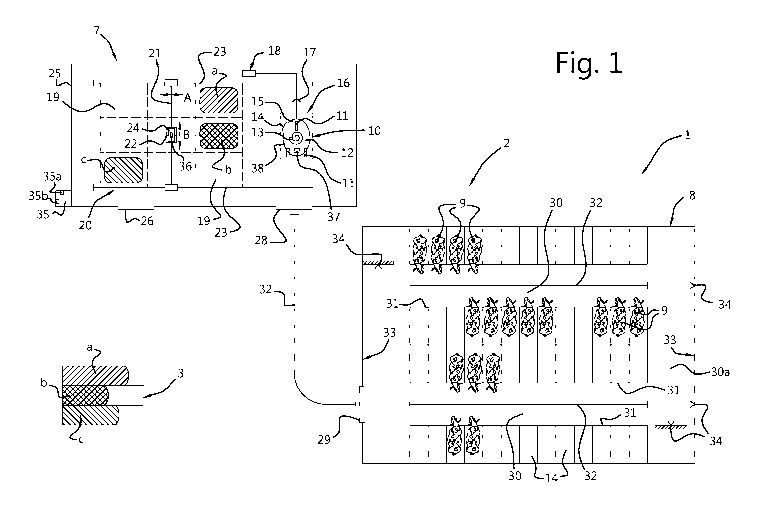
The feeding system for feeding animals, in particular cows, such as dairy
cows or meat cows, is denoted overall by reference numeral 1 in Figure 1. The
feeding
system 1 is arranged in an operational area 2. The feeding system 1 comprises
a feed
storage 3 containing a plurality of feed types a, b, c, a feed supply 7
containing the same
feed types a, b, c, an animal shed 8 containing the animals 9, and an
autonomous feeding
device 10 for feeding the animals 9 feed from the feed supply 7. Although the
feed storage
3 shown diagrammatically in Figure 1 comprises three adjacent silos containing
feed
types a, b, c, for example silage, the feed storage 3 may comprise further
storage devices
and/or types of feed, such as tower silos containing bulk feed, for example
corn, potatoes
and/or beets, or pressed bales. In the same way, the feed supply 7 may also
contain more
than the three feed types a, b, c shown in Figure 1. Obviously, the
operational area 2 may
optionally also contain a dwelling, one or more further animal sheds, sheds
and other
buildings (not shown).
In this exemplary embodiment, the autonomous feeding device 10 for
feeding the animals 9 is configured as a self-propelled feed wagon. Obviously,
it is
possible, according to the invention, for the feeding system 1 to comprise
more than one
autonomous feed wagon 10, in particular two autonomous feed wagons 10 (not
shown).
By means of wheels 11, the feed wagon 10 is movable across a floor, farmyard
or other
ground surface. The feed wagon 10 comprises a container 12 for accommodating a
batch
of feed. In this exemplary embodiment, a mixing device 13 for cutting and/or
mixing feed
is provided in the container 12. A dispensing device 14 is provided in order
to dispense
and/or dose the feed from the container 12. The dispensing device 14
comprises, for
example, a door which is displaceable between a closed and an open position.
The feed wagon 10 is autonomously displaceable by means of a driving and
steering system for driving and steering the feed wagon 10 (not shown). The
driving and
CA 03164816 2022-06-14
WO 2021/125949
PCT/NL2020/050793
17
steering system of the feed wagon 10 is controllable by means of a control
unit 15 of the
feed wagon 10. In this exemplary embodiment, the driving and steering system
comprises
an electrical drive motor (not shown) for each rear wheel 11. The electrical
drive motors
of the rear wheels 11 are controllable independently from one another. By
controlling the
rotary speed of the rear wheels 11, the feed wagon 10 can travel forwards or
backwards
in a straight line or make a bend.
The driving and steering system comprises a battery system for storing
electrical energy (not shown). The battery system is connected to the
electrical drive
motors. In Figure 1, the feed wagon 10 is situated at a feed loading station
16, at which
the container 12 of the feed wagon 10 is filled with feed. The feed loading
station 16
comprises a charging point 17 of a charging system 18 for charging the battery
system of
the feed wagon 10. The feed loading station 16 therefore also acts as a
charging station.
The control unit 15 of the feed wagon 10 is configured to control the mixing
device 13 in
such a way that the mixing device 13 mixes the feed contained in the container
12, while
the feed wagon 10 is connected to the charging point 17 and the battery system
of the
feed wagon 10 is charged by means of the charging system 18.
In this exemplary embodiment, the feed supply 7 forms a feed kitchen, i.e.
an intermediate feed storage. The feed kitchen comprises a number of feed
storage areas
19 to accommodate the feed types a, b, c and optionally further feed types
(not shown).
The feed storage areas 19 are separated from each other - the feed storage
areas 19
are, for example, formed by delineated spaces on a floor, on which a silage
block or a
pressed bale is situated. Also, one or more of the feed storage areas 19 may
comprise a
trough for accommodating bulk feed, such as corn, potatoes or beets. The
capacity of the
feed kitchen 7 is, for example, limited to a number of days. The quantities of
feed of the
feed types a, b, c which can be accommodated in the feed kitchen 7 are smaller
than the
quantities of feed of these feed types a, b, c which are stored in the feed
storage 3.
A feed-loading system 20 is provided for transferring feed from the feed
kitchen 7 to the container 12 of the feed wagon 10 if the feed wagon 10 is
positioned at
the feed loading station 16. In this exemplary embodiment, the feed-loading
system 20
comprises a movable carrying rail 21 which is displaceably (see arrow A)
arranged on
two fixed carrying rails 23 which are arranged mutually parallel to and spaced
apart from
each other. The movable carrying rail 21 comprises a trolley 22 which is
displaceable
along the former (see arrow B). The trolley 22 is provided with a vertically
displaceable
feed grab 24 to grab feed from the feed storage areas 19. The feed grab 24
suspended
from the trolley 22 can be displaced in a substantially horizontal plane so as
to be situated
CA 03164816 2022-06-14
WO 2021/125949
PCT/NL2020/050793
18
above each of the feed storage areas 19.
The feeding system 1 according to the invention comprises a control system
35 with a memory 35a. Although the control system 35 in Figure 1 is shown
diagrammatically on the left-hand side, the control system 35 could also be
arranged in a
different location. The memory 35a may comprise a storage facility on a
computer of the
farm or a server at the manufacturer of the feeding system 1 which is
connected to the
control system 35 via the internet, a cloud storage or something else.
The feed grab 24 is controlled by the control system 35. Ration data are
stored in the memory 35a. The ration data comprise, for example, a plurality
of rations for
different groups of animals 9. Based on the ration data of a selected ration,
i.e. mixed
feed of feed types in a desired ratio (kg), the feed grab 24 takes quantities
of the feed
types a, b, c from the feed storage areas 19 to the container 12 of the feed
wagon 10,
while the feed wagon 10 is situated at the feed loading station 16, in such a
way that that
the selected ration is accommodated in the container 10. By transferring a
plurality of feed
types to the container 12 of the feed wagon 10, a batch of mixed feed of feed
types is
produced therein according to the selected ration, i.e. a batch of mixed feed
(kg) of feed
types in a desired ratio.
In other words, in order to compose the batch of feed, the feed grab 24 in
each case takes a quantity of feed from one of the feed storage areas 19, the
feed grab
24 displaces that feed across the feed storage areas 19 until it is above the
container 12
of the feed wagon 10 and then drops that feed into the container 12. The feed
wagon 10
comprises a weighing device 37 which is configured to measure the weight (kg)
of the
feed which is accommodated in the container 12. The weighing device 37 is
connected
to the control system 35. When loading a batch of feed into the container 12
of the feed
wagon 10, the control system 35 monitors how much feed (kg) of each feed type
a, b, c
is loaded into the container 12.
Obviously, the feed supply 7 and the feed-loading system 20 may also be
configured differently. The feed grab 24 may, for example, also be
incorporated in the
feed wagon 10. In that case, the feed grab 24 of the feed wagon 10 loads the
container
12 with the desired quantity of feed of the desired composition, in particular
directly from
the feed storage 3. Furthermore, instead of or in addition to the feed storage
areas 19
shown in Figure 1, the feed supply 7 may comprise one or more other feed
supply
devices, such as a driven conveyor belt for holding pressed bales or blocks
cut from a
silo in combination with a releasing device for releasing feed from such a
bale or block,
for example a cutter or blade, in particular a so-called "bale shredder",
and/or a trough for
CA 03164816 2022-06-14
WO 2021/125949
PCT/NL2020/050793
19
bulk feed comprising an auger for the metered discharge of the feed, such as a
so-called
"commodity box", and/or a tower silo and/or something else. In this case, the
feed-loading
system may be provided with one or more driven conveyor belts for displacing
the feed
from the or each feed supply device to the container 12 of the feed wagon 10.
In addition, it is possible for the feed not to be mixed and/or cut in the
container 12 of the feed wagon 10, but in a stationary mixer which is arranged
near the
feed supply 7 (not shown). In that case, the feed grab 24 loads a batch of
feed from the
feed supply system 7 into the stationary mixer. Following mixing and/or
cutting by means
of the stationary mixer, the mixed feed is loaded into the feed wagon 10.
Thus, the
container 12 of the feed wagon 10 does not have to contain a mixing device. In
this case,
it is possible for the stationary mixer in each case to receive a quantity of
feed which
corresponds to a single batch of feed for the container 12 of the feed wagon
10. However,
the stationary mixer may also have capacity to accommodate and prepare a
plurality of
batches of feed for the container 12 of the feed wagon 10. The quantity of
feed in the
stationary mixer then forms a premixed quantity of feed which is supplied to
the container
12 of the feed wagon 10 in portions, i.e. for a plurality of feeding rounds.
The feed kitchen 7 is surrounded by a safety fence 25. An access door 26
is provided in the safety fence 25, so that, for example, a fork-lift truck or
tractor can enter
the feed kitchen 7 via the access door 26 in order to replenish the feed
storage areas 19
with the different feed types a, b, c from the feed storage 3. In addition,
the safety fence
comprises a passage door 28 for the feed wagon 10. The feed wagon 10 can enter
and exit the feed kitchen 7 via the passage door 28. Obviously, it is possible
that the
safety fence 25 only comprises one door, via which both the feed wagon 10 and
the
tractor or fork-lift truck can enter and exit the feed kitchen 7. Also, the
safety fence 25 in
25 Figure
1 may extend to the left of the feed loading station 16 and the passage door
26, in
which case the safety fence 25 protects the feed kitchen 7 containing the feed
storage
areas 19, but the feed loading station 16 is freely accessible via the passage
door 26 (not
shown).
In addition to the safety fence 25, the feeding system 1 may comprise further
safety features, for example an emergency stop by means of which the feed
wagon 10
and/or the feed-loading system 20 is stopped immediately. In this case, for
example, an
alarm may sound and/or a message may be sent to a user, such as an e-mail or
text
message.
The animal shed 8 comprises a door opening 29, via which the feed wagon
10 can enter and exit the animal shed 8. The door opening 29 is closable by
means of a
CA 03164816 2022-06-14
WO 2021/125949 PC
T/NL2020/050793
shed door which is preferably openable automatically. In this exemplary
embodiment, the
animal shed 8 has two feeding alleys 30. Obviously, more or fewer feeding
alleys may be
provided. In this exemplary embodiment, each feeding alley 30 is delimited on
either side
by a feeding fence 31. In other words, the animal shed 8 comprises four
feeding fences
5 31. The feeding fences 31 each form a feeding place for feeding the animals
9. The
animals 9 may be situated next to each other along the feeding fence 31. The
animals 9
are positioned with their head turned towards the feeding alley 30 and are
able to put
their head through the feeding fence 31 in order to eat feed which has been
deposited
along the feeding fence 31 by the feed wagon 10.
10 The feeding fences 31 in the animal shed 8 are situated at a
distance from
the feed loading station 16 of the feed kitchen 7. Each of the feeding fences
31 is
reachable by the feed wagon 10 from the feed loading station 16. Various
beacons are
arranged in the operational area 2. In this exemplary embodiment, the beacons
are
formed by strips 32 which are disposed in or on a floor or another ground
surface, walls
15 33 of the animal shed 8 and impact points 34. The feed wagon 10
comprises a sensor
system (not shown) which is configured to cooperate with the beacons 32, 33,
34. In
addition, the feed wagon 10 comprises a gyroscope (not shown) in order to
travel straight
ahead over a predetermined distance. The gyroscope is connected to the control
unit 15
of the feed wagon 10.
20 In addition to the ration data, the memory 35a of the control system
35
contains various other data, such as navigation data and operating data. The
navigation
data comprise beacon data of the beacons 32, 33, 34. On the basis of the
navigation
data, the feed wagon 10 can travel different routes from the feed loading
station 16 to and
through the animal shed 8. The operating data comprises, for example,
operating data
for operating the dispensing device 14 of the feed wagon 10.
According to the invention, the feed wagon 10 comprises a feed-quantity
measuring device 38 for measuring a feed-quantity value for the quantity of
feed for
consumption by the animals 9 which is situated along the feed fence 31 which
the feed
wagon 10 passes. The feed-quantity measuring device 38 comprises, for example,
a laser
which measures the feed height (h in cm) of the feed along the feed fence 31.
The quantity
of feed at the feed fence 31 can be calculated on the basis of the measured
feed height
h. In this exemplary embodiment, the feed-quantity measuring device 38 is
fitted to the
feed wagon 10. The feed-quantity measuring device 38 measures the feed-
quantity value
h while the feed wagon 10 drives past the feed fence 31. Every time the feed
wagon 10
drives past the feed fences 31, the feed-quantity measuring device 38 measures
the
CA 03164816 2022-06-14
WO 2021/125949
PCT/NL2020/050793
21
associated feed-quantity values h.
In this exemplary embodiment, the feed wagon 10 comprises a feed-
pushing device for pushing or piling up feed in a direction at right angles to
the direction
of travel of the feed wagon 10 (not shown), i.e. the feed-pushing device
pushes feed
which is situated along the feed fence 31 and which the animals 9 moved away
from the
feed fence 31 during eating, back towards that feed fence 31. The feed-
quantity
measuring device 38 is fitted to the feed wagon 10 in such a way that the feed
which has
just been deposited by the dispensing device 14 is included, i.e. the
dispensing device
14 first doses out the feed from the container 12 in front of the feed fence
31 and
immediately thereafter the feed-quantity measuring device 38 measures the feed-
quantity
value at that feed fence 31. This measured feed-quantity value depends on the
quantity
of feed which had not yet been eaten, i.e. was dispensed earlier and was
pushed back to
the feed fence 31, and on the quantity of fresh feed which was dosed out at
that feed
fence 31.
The control system 35 is configured to receive the feed-quantity values
measured along the feed fences 31. The feed-quantity values are first
temporarily stored
in a memory of the control unit 15 of the feed wagon 10. After the feed wagon
10 has
returned to the feed loading station 16, the measured feed-quantity values are
sent to the
control system 35 and stored in the memory 35a of the control system 35. The
longer the
feeding system 1 according to the invention is in operation, the more feed-
quantity values
are stored in the memory 35a, which have been measured at different
measurement
instants. By means of the memory 35a, the control system 35 is given large
quantities of
data regarding the course of the measured feed-quantity values over time at
each of the
various feed fences 31.
Figures 2A, 2B show graphs of measured feed-quantity values, which are
stored in the memory 35a, for two feed fences 31 during a day and a plurality
of days,
respectively. In reality, feed-quantity values are stored and retained in the
memory 35a
of the control system 35 for a plurality of months or more. As is illustrated
in the graphs,
the feed-quantity value at each feed fence 31 in each case decreases over time
until feed
from a subsequent batch of feed is dosed out at that feed fence 31. The rate
at which the
feed-quantity value decreases, i.e. the rate of consumption, is different for
each feed
fence 31. This depends, for example, on the number of animals 9 along the feed
fence
31 and the lactation stage of those animals 9, such as high-yield dairy cows,
low-yield
dairy cows, dry dairy cows, etc. In addition, the rate of consumption at each
feed fence
31 varies throughout the day (24 hours). The rate of consumption depends on
the day
CA 03164816 2022-06-14
WO 2021/125949
PCT/NL2020/050793
22
and night rhythm of the animals 9.
The control system 35 according to the invention is programmed by means
of a self-learning algorithm 35b which is configured to recognize
correlations, i.e.
statistical relations, between the feed-quantity values measured at different
measurement
instants and stored in the memory 35a. In this exemplary embodiment, the self-
learning
algorithm 35b is configured to receive examples of input and output for each
feed fence
31. The input of each example comprises a feed-quantity value at a measurement
instant,
a value which is representative of that measurement instant, and further time-
dependent
parameters, such as the time elapsed since the last feed deposit at that feed
fence 31
and/or the quantity of feed (kg) which has been dispensed at that feed fence
31 during a
previous period of a preset duration, for example the previous 5 hours or 10
hours. The
output ("target") of each example comprises an associated value for the rate
of
consumption. The self-learning algorithm 35b is trained by means of such
examples.
The examples for each feed fence 31 are analyzed by dividing the feed-
quantity values stored in the memory into groups overtime. Each group starts
with a feed-
quantity value which is measured directly after feed has been dispensed, and
ends with
a feed-quantity value which is measured immediately before feed from a
subsequent
batch is dispensed. The memory of the control system 35 stores the instances
when the
feed wagon 10 drives to dispense feed or to pile up feed, i.e. the control
system 35 records
whether a feed-quantity value is measured immediately after feed has been
dispensed at
the feed fence 31.
In this case, each group of feed-quantity values (ha) is analyzed, as is
illustrated in Figure 3, which diagrammatically shows a course of amount of
feed over
time at one of the feed fences 31. The feed-quantity values h_1, h_2, , h_n
measured at
different measurement instants are illustrated by means of closed dots. The
current time
is denoted by to. The feed-quantity values hi, h_2, , h-
n, which are situated to the left of
instant to in Figure 3, were measured in the past and stored in the memory 35a
of the
control system 35. Based on these feed-quantity values hi, h_2, ,
h_n, which may, in
practice, comprise for example two months, i.e. many more than the eight feed-
quantity
values hi, h_2, h-8 shown in Figure 3, the control system 35 calculates the
feed-quantity
values hi, h2, ,
hn after the last measurement instant, in this case in the future, using
the self-learning algorithm 35b.
To this end, the control system 35 first calculates, for each group of feed-
quantity values (ha), by means of a function fit ("curve fit"), a value for a
parameter A in
an exponential function with Net, in which A is representative of the rate of
consumption,
CA 03164816 2022-06-14
WO 2021/125949
PCT/NL2020/050793
23
t is the time, and N is a constant, such as 100. This means that the feed-
quantity values
in each case assume an exponential course over time. In this case, each
example with
which the self-learning algorithm 35b is fed comprises a feed-quantity value
h_n at a
measurement instant, a value which is representative of that measurement
instant, and
further time-dependent parameters as input, and an associated value for the
parameter
A as output ("target"), which value is calculated using a function fit.
The self-learning algorithm 35b is then able to recognize correlations, i.e.
statistical relations, between the input and the output. Based on the
recognized
correlations, the algorithm can then predict a value for the parameter A,
which forms a
measure for the rate of consumption at the feed fence 31 at and/or after the
last
measurement instant, as output. In other words, if the last-measured feed-
quantity value
stored in the memory is presented as input to the algorithm in combination
with an
associated value which is representative of that last measurement instant and
further
time-dependent parameters, the self-learning algorithm 35b produces a value
for the
parameter A as output. Thus, an exponential function N.em is fixed which runs
through the
last-measured feed-quantity value hi stored in the memory. The control system
35 can
then easily calculate the feed-quantity values hn at points in time after the
last
measurement instant on the basis of the predicted exponential function.
In this exemplary embodiment, the self-learning algorithm 35b therefore
uses the last-measured feed-quantity value hi stored in the memory 35a as a
starting
point for the prediction. This last-measured feed-quantity value hi and the
associated
time-dependent parameters together form an input for the self-learning
algorithm 35b.
Based on this input, the self-learning algorithm 35b, after having been
trained sufficiently
by means of pattern recognition in the received examples, determines the value
for the
rate of consumption in the form of the parameter A at the feed fence 31, at
and/or after
the last measurement instant, as output, i.e. a value which is representative
of the rate at
which the quantity of feed which is present at the feed fence 31 for
consumption by the
animals, decreases at that feed fence 31. By means of the calculated value for
the rate
of consumption, the control system 35 can then calculate the feed-quantity
values hi, h2,
... , hn at points in time after the last measurement instant by means of this
value for the
rate of consumption. These calculated feed-quantity values hi, h2, hn
are indicated by
open dots in Figure 3. As a result thereof, the feeding system 1 takes into
account
variations in the rate of consumption, so that the feeding system 1 can
deliver the
subsequent batch of feed at the feed fence 31 (virtually) exactly at a desired
time.
In this exemplary embodiment, the control system 35 assumes that the
CA 03164816 2022-06-14
WO 2021/125949
PCT/NL2020/050793
24
quantity of feed at the feed fence 31 exponentially decreases to an asymptotic
value 0.
In practice, the animals 9 do not finish the feed entirely, but a small
quantity of residual
feed remains at the feed fence 31 which is not, or hardly, eaten by the
animals 9. In this
exemplary embodiment, a threshold value a is chosen and set manually in the
control
system 35, for example by the farmer or a service technician, and corresponds
to a
residual feed quantity value which, in practice, occurs on the farm. The
control system 35
determines when the predicted, future feed-quantity value at the feed fence 31
drops
below this threshold value a. At the instant that the future feed-quantity
value drops below
the threshold value a, the feed fence 31 is effectively empty, i.e. the feed
has finished,
even if there is still a small quantity of residual feed present. That future
depletion time or
instant for the feed fence 31 is denoted by t2 in Figure 3.
The control system 35 determines a starting time ti to start loading a
subsequent batch of feed into the container 12 of the feed wagon 10 by
calculating back
from that future depletion time t2 by at least such a time interval x that the
subsequent
batch of feed is dispensed at the feed fence 31 by the feed wagon 10 before
the animals
9 have substantially finished the feed at that feed fence 31. In other words,
the control
system 35 sends a start command to the feed-loading system 20 at the starting
time ti to
start loading the subsequent batch of feed into the feed wagon 10, so that
there is
sufficient time to load and mix the subsequent batch of feed in the container
12 of the
feed wagon 10, drive to the feed fence 31 and dose out the feed before the
feed at that
feed fence 31 effectively finishes.
The time interval x may be chosen to be fixed for each feed fence 31 in the
control system 35. The fixed time interval x is input, for example manually,
into the control
system 35 by a farmer or service technician, preferably based on experiences
of the time
period which is required from the start command to the feed-loading system 20
to start
loading the subsequent batch of feed to the actual dosing out of the feed at
the feed fence
31 by the feed wagon 10. However, the fixed time interval x may also be
adjusted
automatically by the control system 35. The fixed time interval x is, for
example, between
minutes and 3 hours. In practice, such a time interval x is usually sufficient
to prepare
30 the subsequent batch of feed and take it to the feed fence 31 and
dispense it there.
However, it is also possible for the time interval x to be variable. The
control
system 35 determines the time interval x, for example in dependence on the
selected
ration. The required time period for preparing the subsequent batch of feed
depends on
the selected ration. The control system 35 can request for each ration how
long it takes
to prepare the subsequent batch of feed according to that ration in the feed
wagon 10. In
CA 03164816 2022-06-14
WO 2021/125949 PC
T/NL2020/050793
addition, the time the feed wagon 10 requires to drive to the various feed
fences 31 may
vary. The control system 35 may determine a delivery time or travel time for
driving a
route to the various feed fences 31, and also make the time interval x
dependent thereon.
After the control system 35 has given the start command to the feed-loading
5 system 20 at the starting time ti to start loading the subsequent batch
of feed according
to the selected ration into the feed wagon 10, the feed wagon 10 is loaded
with this
subsequent batch of feed and the feed wagon 10 then drives autonomously to the
one or
more feed fences 31 with a feed requirement in order to dose out the feed for
the animals
9.
10 In practice, a farm virtually always has a plurality of feed fences
31. When
the feed at one of the feed fences 31 finishes, the feed wagon 10 will
automatically add
feed at that feed fence 31. In this case, the feed wagon 10 may drive a route
along a
plurality of feed fences 31, so that feed-quantity values are measured at this
plurality of
feed fences 31. Since the feeding system 1 according to the invention stores
the
15 measured feed-quantity values in the memory 35a, and the control system
35 determines
the starting time ti to start preparing the subsequent batch of feed on the
basis of an
accurately predicted depletion time, it is hardly necessary, if at all, to
make the feed
wagon 10 drive just in order to collect feed-quantity values. If the feed
wagon 10 only
measures feed-quantity values when delivering feed or piling up feed, and in
doing so
20 drives a route along one or more of the feed fences 31, the control system
35 has
sufficient feed-quantity values to accurately determine the starting time ti.
Instead of or in addition to predicting the future depletion time t2, i.e. the
moment at which the feed at the feed fence 31 is effectively finished, the
control system
can predict a depletion time duration y for the feed fence 31 (see Figure 3).
The
25 depletion time duration y indicates how long it takes before the
predicted, future feed-
quantity value hn at the feed fence 31 drops below the preset threshold value
a for the
quantity of feed at that feed fence 31. The depletion time duration y may also
be
determined on the basis of the feed-quantity values h_n stored in the memory
35a, in
particular by means of the rate of consumption at the feed fence 31 determined
by the
30 self-learning algorithm 35b. The control system 35 then calculates the
starting time ti on
the basis of this depletion time duration y for the feed fence 31. To this
end, the control
system 35 may directly compare the depletion time duration y for the feed
fence 31 to the
time interval x for preparing the subsequent batch of feed and delivering that
feed. It is
therefore not necessary to explicitly determine the future depletion time t2
in the control
35 system 35.
CA 03164816 2022-06-14
WO 2021/125949
PCT/NL2020/050793
26
The invention is not limited to the exemplary embodiment illustrated in the
figures. The person skilled in the art may make various modifications without
departing
from the scope of the invention. Instead of calculating the future feed-
quantity values by
means of a predicted rate of consumption, the self-learning algorithm may also
directly
predict the future feed-quantity values on the basis of the measured feed-
quantity values
stored in the memory. In other words, in this case the self-learning algorithm
is fed
examples which each comprise a feed-quantity value measured at a measurement
instant in combination with associated values of time-dependent parameters as
input, and
a feed-quantity value measured after that measurement instant as output. After
sufficient
examples have been presented to the self-learning algorithm, the self-learning
algorithm
is able to predict one or more future feed-quantity values as output, based on
the last-
measured feed-quantity value and associated time-dependent parameters. In
addition,
the control system may be configured to calculate a value of a different feed
variable than
the feed-quantity value, such as a feed variable which is representative of a
time period
until a subsequent start command to start loading a subsequent batch of feed
is desired.
In this case, such a time period may be added in each case to each measured
feed-
quantity value stored in the memory. In other words, the control system may
first convert
the measured feed-quantity values to an associated time period until the next
start
command. Subsequently, the control system may calculate, on the basis of the
converted
values of this time period, one or more values for this time period at the or
each feeding
place at one or more points in time after the last measurement instant. In
this case, the
control system therefore does not have to predict feed-quantity values, but
the control
system can directly predict the time period until the next start command is
desired.
According to the invention, it is also possible for the control system to use
the one or more
calculated feed-quantity value or values of a different feed variable in a way
other than to
set the point in time at which feed from the subsequent batch of feed is
delivered at the
one or more feeding places. In addition thereto or instead thereof, the
control system
may, for example, send a message to a smartphone dependent on the calculated
feed-
quantity value(s).