Note: Descriptions are shown in the official language in which they were submitted.
WO 2021/155445
PCT/AU2021/050102
DIRECT LASER TRABECULOPLASTY METHOD AND APPARATUS
FIELD of INVENTION
This invention relates to an ophthalmic treatment of human eyes and more
specifically
to the treatment of glaucoma using a laser beam, whereby it is directed at the
trabecular
meshwork to initiate reactions that promote improved drainage of aqueous
humour
fluid.
The invention relates to an ophthalmic apparatus for treating glaucoma in a
patient's
eye.
The invention relates further to a method of treating glaucoma.
BACKGROUND
Glaucoma is a disease in which vision is impaired as a result of damage to the
optic
nerve or retina, and is responsible for about 25% of blindness in developed
countries.
A common contributor to this damage is elevated pressure of the fluid, known
as the
aqueous humour, within the eye. The increased intra-ocular pressure causes
progressive
death of retinal ganglion cells and damages axons that transfer visual
information to a
brain via an optic nerve. The aqueous fluid is constantly and slowly replaced
by the
body with the ingress coming from a ciliary body just beneath the iris and a
balancing
drainage taking place through an annular spongy tissue, known as a trabecular
meshwork around the edge of the iris where it meets the cornea which
transitions into
the sclera. Drainage takes place from the meshwork through to a structure
called
Schlemm' s canal and eventually into the body's circulatory system.
The primary cause of elevated pressure in an eye is due to an imbalance
between the
ingress and egress of fluid due to malfunctioning of the annular trabecular
meshwork.
This meshwork provides drainage of the fluid through ducts that are
distributed around
the trabecular annulus, however with age these ducts become blocked with
cellular
debris. Methods to improve the drainage have hitherto been attempted with
either
medication or surgical means. A more recent method, known as laser
trabeculoplasty,
relies on directing a pulsed, focused laser beam onto the trabecular meshwork
with
sufficient intensity that pigmented melanin cells suffer damage and initiate
biological
changes whereby laser-damaged sites are repopulated by cells from a non-
filtering
1
CA 03165061 2022- 7- 15
WO 2021/155445
PCT/AU2021/050102
region of the trabecular meshwork. These have been found to serve as stem
cells
producing fresh and functioning cells that have been found to restore the
drainage by
the trabecular meshwork.
Currently, delivery of a laser beam to the trabecular meshwork is achieved by
directing
a laser beam obliquely through the cornea of an eye with the aid of an optical
element
placed in contact with the eye, the element including a mirror to direct the
laser beam
sideways to the trabecular meshwork. This treatment method is known as
selective laser
trabeculoplasty or SLT. With this system an ophthalmic practitioner is
required to rotate
the optical element to treat multiple regions around the trabecular meshwork.
When
sufficient intensity is achieved, the reaction can be identified by production
of micro -
bubbles. It is the production of microbubbles that the detection of which
indicates that
the treatment laser energy is sufficient.
The shortcomings of this method are several-fold: It can be difficult for a
practitioner
to accurately direct the beam to a desired spot on the trabecular meshwork
(TM); the
procedure requires great skill to avoid risks of injury and infection; and
lastly the
procedure can be quite lengthy thereby causing discomfort to the patient.
An improvement to the technique has been proposed in a patent application by
Belkin
(US 2015 0 366 706 Al) in which a treatment laser beam is directed at the
trabecular
meshwork through the sclera. The deficiency in this method is that neither the
ideal
dose nor the exact location of a TM is known, both of these parameters are
assumed in
the application whereas in reality the exact position of the TM is unknown and
the
required energy dose is speculative. The position or diameter of the TM
relative to the
iris varies between individuals and generally it cannot be seen through a
sclera. The
intensity of beam necessary to induce damage to the melanin cells cannot be
readily
determined as it depends on scattering and absorption in a sclera, the extent
of which
varies between individuals and on the location along the trabecular meshwork.
OBJECT of INVENTION
The object of this invention is to provide a method or apparatus for treating
a trabecular
meshwork in an eye in a fashion so that the treatment laser beam location and
intensity
has the potential to be automatically controlled and an operator has minimal
involvement with the procedure after it has been initiated.
2
CA 03165061 2022- 7- 15
WO 2021/155445
PCT/AU2021/050102
This objective is achieved by delivering a treatment laser beam through the
sclera of an
eye at a location and with an energy dose that is determined by detecting and
analysing
a back-scattered reflection of light from a probe light beam directed at one
or more
regions near the trabecular meshwork.
This invention provides an uncomplicated means to perform a selective laser
trabeculoplasty procedure through a sclera from the front of an eye without
any optics
contacting the eye.
Furthermore, in the broadest sense, the position of the trabecular meshwork
does not
need to be known accurately, though a method described below allows a
sufficiently
accurate method of determining its position.
This invention can be further described as a method or apparatus for treating
glaucoma
whereby a pulsed treatment laser beam is focused behind the sclera and through
to a
trabecular meshwork of an eye, the method characterised by including a probe
beam of
light coupled to an optical coherence tomography sub-system that both
identifies the
location of the meshwork and detects when micro-bubbles have been formed
during a
phase in which the energy of the treatment laser beam is increased.
In another form, this invention can be described as a method or apparatus for
treating
glaucoma whereby a treatment pulsed laser beam is focused behind the sclera
and
through to a trabecular meshwork of an eye, the method characterised by
sequentially
projecting, using scanning means, a multitude of segmented lines spanning
between an
inner and outer radii (with reference to the centre of an iris) and the laser
beam energy
being set to be sufficient to cause damage to the melanin cells in the
trabecular
meshwork.
The treatment laser beam energy is determined by performing an initial test in
which
the energy is increased after each radial scan until micro-bubbles are formed,
the
formation being detected by a change in the backscattered intensity of a probe
beam of
light, the change resulting from the gas-liquid interfaces that are generated.
The laser probe beam can either be the same as the treatment beam or a
separate laser
beam of more optimal wavelength and intensity.
In an alternative form of the invention, the location of the TM is determined
in a
multitude, such as 8 or 16 or more, radial locations and an interpolation
performed to
determine its location at different radial orientations. The locations are
recorded with
3
CA 03165061 2022- 7- 15
WO 2021/155445
PCT/AU2021/050102
reference to the outer diameter of the iris that is subsequently used as a
reference
location using digital imaging means.
In this description, it is recognised that a treatment beam will not focus
sharply behind
the sclera on account of scattering in the translucent tissue, nevertheless it
is this
condition that will be referred to as one in which a beam is focussed.
With regard to an additional aspect of the invention the task of the invention
is solved
by an ophthalmic apparatus for treating glaucoma in a patient's eye comprising
a
treatment laser module delivering a treatment laser beam, and comprising a
detection
system for detecting micro-cavitation, in particular micro-bubbles, formed on
account
of the treatment laser beam in the patient's eye, in particular at the
trabecular meshwork
of the patient's eye.
If the location, and/or the time, and/or the levels of micro-cavitation
respectively of
micro-bubbles is better known, it is possible to minimise the energy delivered
to the
eye and to minimise the duration of the treatment.
Insofar the detection system allows an additional position control to control
the position
of the micro-cavitation at the trabecular meshwork.
This alone is an advantageous further development of existing methods for the
treatment of glaucoma.
In regard to a further aspect of the invention the present task at hand is
solved by an
ophthalmic apparatus for treating glaucoma in a patient's eye comprising a
treatment
laser module delivering a treatment laser beam, and comprising a detection
system for
detecting the location in 2 or 3 dimensions and/or the shape, in particular a
possible
asymmetry, of the trabecular meshwork of the patient's eye.
If the location and/or the shape is better known before treatment, it is
possible to
minimise the energy delivered to the eye and to minimise the duration of the
treatment.
Therefore, on the one hand the detection system can be equipped with an
additional
position control to detect the position of the trabecular meshwork and its
shape,
preferably before activation the treatment laser module.
Thus, the setup can also comprise an ophthalmic apparatus for measuring the
eye, in
particular the trabecular meshwork of the eye.
On the other hand, the detection system allows for a position control to
control the
position of the micro-cavitation.
4
CA 03165061 2022- 7- 15
WO 2021/155445
PCT/AU2021/050102
This alone is an advantageous further development of existing methods for the
treatment of glaucoma.
It is also possible to correct the position of the micro-cavitation,
preferably live during
the treatment.
In both cases it is possible to modulate the treatment laser beam in
dependence of the
information provided by the detection system.
The detection system may be constructed in different ways.
Constructively simple yet precise solutions can be realised if the detection
system
comprises a tomography system for detecting micro-cavitation.
Cumulatively or alternatively the detection system can comprise an optical
coherence
tomography (OCT) system for detecting the location and/or the shape,
especially a
possible asymmetry and/or micro-cavitation.
The detection system can comprise more components, like a camera, a
controller, a
processor, a scanner or the like.
It is further advantageous, if the apparatus comprising an eye-probe sub-
system emits
a co-axial probe beam. This allows the treatment site in the eye to be
observed
particularly well.
If beams focused behind the sclera of a patient's eye and through to a
trabecular
meshwork of a patient's eye, contactless treatment of the eye can be carried
out without
any problems.
The task of the invention is additionally fulfilled by an ophthalmic apparatus
for
treating glaucoma comprising a treatment laser module delivering a treatment
laser
beam to a scanner and an objective focusing lens, and comprising a co-axial
probe beam
emitted from an eye-probe sub-system, said beams focused behind the sclera and
through to a trabecular meshwork of a patient's eye, the apparatus including a
detector
preferably within the eye-probe sub-system that senses backscattered light
from the
probe beam and detects the formation of micro-bubbles formed on account of the
treatment laser beam inducing damage to the melanin cells in the trabecular
meshwork.
This solution describes a concrete possible apparatus with which the invention
can be
well realised. Especially, it is possible to minimise the energy delivered to
the eye and
to minimise the duration of the treatment, as well.
CA 03165061 2022- 7- 15
WO 2021/155445
PCT/AU2021/050102
Furthermore, it is particularly advantageous, if the apparatus comprises an
energy
control system, which modulates the treatment laser beam in dependence on
information of the detection system. In this case, the required energy for the
treatment
laser beam can depend on the formation of micro-cavitation or micro-bubbles,
and/or
on the shape of the areas of the eye to be treated, in particular the
trabecular meshwork.
In particular, with a suitably designed energy control system, the intensity,
the duration
or the like of the energy level of the treatment laser beam can be determined
in
dependence on the onset, the progress, the intensity or the like of a
formation of micro-
cavitation or micro-bubbles.
With regard to an alternative construction method, it is advantageous, if an
eye-probe
sub-system comprises an optical coherence tomography (OCT) system that further
determines the location of the trabecular meshwork prior to delivery of the
treatment
laser beam. This allows the apparatus to be realised in a structurally simple
way.
If an eye-probe sub-system comprises a photo-detector, the observation of
specific
treatment areas of the eye can be performed more compactly.
It is understood that the treatment laser beam and the probe beam can be
provided
independently from each other. If the probe beam is identical with the
treatment laser
beam, it is possible to further simplify the construction of the apparatus.
A particularly robust and error-free design with regard to the laser beams
used can be
achieved, if the wavelength of the treatment laser beam is in the absorption
range of
melanin cells and the probe beam is infra-red.
With regards to a further aspect of the invention the present task is solved
by a method
for treating glaucoma characterised by determining through a sclera the
location and/or
the shape of a trabecular meshwork and delivering a treatment laser beam to
that
location with a beam's energy sufficient to generate micro-bubbles. This
results in a
particularly locally precise treatment, whereby the energy required to
generate the
micro-bubbles can he set extremely precisely.
Hereby it is possible to minimise the energy delivered to the eye and to
minimise the
duration of the treatment.
In a very advantageous version of the process the energy is controlled and
adjusted
depending on the effect of micro-bubbles and/or the size of the micro-
cavitation, and/or
of the shape and/or location of the trabecular meshwork.
6
CA 03165061 2022- 7- 15
WO 2021/155445
PCT/AU2021/050102
Furthermore, it is advantageous, if an optical coherence tomography system in
a first
step is used to identify the location of the trabecular meshwork, whereupon
the
treatment laser beam is directed at that location and either a preset laser
energy dose is
delivered to the location or the energy dose is increased until the tomography
system
detects micro-cavitation. This allows the treatment site on the eye to be
determined
particularly precisely and then to be processed particularly gently with a
suitably
intensive laser beam.
A particularly preferred process variant provides that the beams follow a
pattern in
accordance with inputs from an energy control system, in particular a
processor and
controller. In this way it can be particularly advantageous to ensure that
only enough
energy can be applied to the treatment area until the micro-bubbles are
formed, which
indicates sufficient treatment of the trabecular meshwork.
Also, it is advantageous, that the pattern comprises radial lines or radial
segments
extending from an inner radius R1 to an outer radius R2, the radii
corresponding to
extremes of the likely position of a trabecular meshwork. This ensures that
only those
areas of the eye are treated with the treatment laser beam, which are
absolutely
necessary for the treatment of glaucoma.
At this point, it is also claimed that the described methods can also be
supplemented by
further technical features described herein, in particular by features of the
apparatus, in
order to advantageously further develop the methods or to be able to represent
or
formulate method specifications even more precisely.
Here it may be explicitly noted, that any characteristics of the previous
figures and/or
claims may be combined if desired to combine and accomplish the effects,
characteristics and advantages cumulatively.
Naturally, the previously mentioned examples of embodiment are only first
design of
the invention. Therefore, the embodiment of the invention is not restricted to
these
variants.
All described characteristics in thc application are claimed as essential to
the invention
as long as they are novel in relation to the state of art, either on their own
or in any
possible combination.
7
CA 03165061 2022- 7- 15
WO 2021/155445
PCT/AU2021/050102
DESCRIPTION of INVENTION
The invention can be better understood by describing two preferred embodiments
illustrated in the accompanying figures in which:
Figure 1 shows a cross-section of an eye featuring a trabecular meshwork.
Figure 2 shows a front-on view of an eye
Figure 3 shows possible laser spot patterns projected onto an eye.
Figure 4 shows a schematic of a preferred embodiment of the invention.
Referring to figure 1, a cornea 1 of a left eye 25 of a patient (not shown)
connects to a
sclera 2. The fluid-filled anterior chamber 3 is contained by the pigment
epithelium or
iris 4 that surrounds the lens 5. The posterior chamber 6 contains vitreous
humor and
represents the largest volume of an eye. Nestled between the outer edges of
the cornea
and the iris is the trabecular meshwork 7, through which drainage is effected
into
Schlem's canal 8. The trabecular meshwork 7 has a triangular cross-section.
Figure 2 shows a left eye 25 as it might be presented to a practitioner. It
shows a pupil
9 surrounded by an iris 10. The adjacent white sclera 11 conceals a trabecular
meshwork 12, shown having exaggerated width within dashed lines.
The width of this meshwork 7 or 12 is typically in the order of 350 microns
with a depth
of 50 ¨ 150 microns.
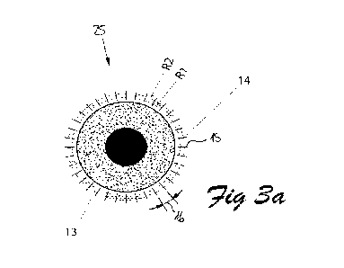
In one preferred embodiment of the invention a system delivers a probe beam 38
(cf.
figure 4) of light that is scanned in a pattern as shown in Figure 3a.
Referring to the figure 3a, a trabecular meshwork 13 lies within an
'uncertainty
annulus' 14 having an inner radius R1 and an outer radius R2.
A probe beam traverses along short radial tines 15 between the inner and outer
radius
R1 and R2, repeating for different orientations around the eye 25 separated by
some
angle 16 of about 1 ¨ 10 degrees.
The choice of angle 16 being a compromise between treatment duration and
sufficient
density of trabecular tissue damage.
While radial lines 15 are shown, other options are possible that traverse
between an
inner and outer radius RI and R2 such as a zig-zag segment 15 in Figure 3b
following
a circular path or angled radial lines 15 such as in Figure 3c.
8
CA 03165061 2022- 7- 15
WO 2021/155445
PCT/AU2021/050102
Curved forms of these patterns could also be used.
While the term 'lines' has been used, this refers to the path of the beam even
though on
a microscopic level the reactive path comprises discrete spots corresponding
to the
digitized location of the probe beam 38 arranged in a line.
The pattern is generated by a conventional galvanometer two-axis scanner 22
(cf. figure
4) or other devices.
Another key aspect of the treatment is determining the energy necessary to
achieve
damage to the melanin cells in the trabecular meshwork 7, 12 resp. 13.
It has been recognised with conventional SLT that one way to ensure damage has
been
achieved is to increase the energy until a vapour gas bubble is fon-tied
within the
meshwork 7, 12 resp. 13.
Conventionally this occurrence is observed by a practitioner, however with
this
invention the production of micro-bubbles is detected by a change in the
backscattered
reflection of an observation or treatment laser beam 21 (cf. figure 4), though
preferably
an observation beam.
Figure 4 illustrates a schematic of a first possible embodiment of the optical
arrangement to achieve delivery of a treatment laser beam 21 and bubble
detection.
Referring to the figure 4, a treatment laser module 20 generates an input
laser treatment
beam 21.
This treatment laser module 20 includes any necessary attenuators, beam
conditioners
and shutters (not shown separately).
The laser treatment beam 21 exiting the treatment laser module 20 is directed
at a 2-
axis scanner 22 that transmits through a dichroic or partial reflector 23 and
through a
focusing lens 24 and onto an eye 25.
An eye-probe system 27 comprises a probe beam of light 38 and a detection
system 40
that will be discussed in more detail below.
The light, especially the probe beam 38, leaving and entering the eye-probe
system 27
has an optical path 41 that is substantially coincident with the treatment
laser beam path
42, with a combination of the paths 41 and 42 achieved with reflector 26.
This reflector 26 is preferably a dichroic mirror (not referenced additional)
tailored for
the reflecting and transmitting wavelengths concerned.
9
CA 03165061 2022- 7- 15
WO 2021/155445
PCT/AU2021/050102
To position and monitor the eye 25, a camera 28 captures light reflected off
the reflector
23.
This camera 28 also provides an image which can be used to determine a scan
pattern
and to provide a record for future reference.
To assist in minimising movement of a patient's eye 25, a fixation spot (not
referenced
additional) is provided at which a patient stare. This fixation spot is
generated by a
visible lamp 29, collimated by lens 30 introduced into the further optical
path 43 of the
camera 28 by partial reflector 31.
The treatment laser module 20 and scanner 22 are controlled by a controller
32, while
a processor 33 performs the necessary electronic and data processing from the
operator,
camera 28 and eye-probe system 27. A display 34 provides an operator
interface.
Other components common with ophthalmic systems such as viewing binoculars for
an
operator, illumination slit lamps or aiming beams have not been shown for ease
of
clarity, however they can be integrated with those components shown in figure
4 by
anyone skilled in the art of medical laser engineering.
The whole system is able to be translated with respect to an eye 25, in order
to focus
the beams 21, 38.
Notably the camera 28 focus is a few hundred microns closer than that of the
treatment
laser 21 and probe beam 38, ensuring that the treatment and probe beams 21 and
38 are
focussed below the sclera 2, 11 if the camera 28 is focussed on the sclera 2
respectively
11.
The eye-probe system 27 will now be discussed in more detail as it can take
several
forms.
Especially the eye probe system 27 or components thereof can realise the
present
detection system 40 or at least components thereof, or vice versa.
In one form suitable for the embodiment described above, the eye-probe system
27
comprises a photo detector 45 able to detect the reflected beam 38 of a probe
beam 38
oh light.
This probe beam 38 of light may be the same as the treatment laser beam 21 or
can be
a separate light beam optimised for the function.
CA 03165061 2022- 7- 15
WO 2021/155445
PCT/AU2021/050102
In order to determine the laser energy of the treatment laser beam 21 required
to produce
damage of melanin cells of the trabecular meshwork 7, 12 or 13, the treatment
laser
beam 21 is repeatedly scanned along one path of a radial segment 15 whilst
increasing
the laser energy until bubble formation is detected.
This threshold power is recorded and stored with a margin, such as 20%, to
ensure
vaporisation is achieved with other segments. The whole pattern is then
scanned with
the laser set at the stored energy.
While the above embodiment and method may be functional, it is desirable to
better
locate the position of the trabecular meshwork 7, 12 resp. 13 in order to
minimise the
energy delivered to the eye and to minimise the duration of the treatment.
The specific location of a trabecular meshwork 7, 12 or 13 can be located by
having
especially the eye-probe system 27 include an optical coherence tomography
(OCT)
system 48. This arrangement represents that of a second preferred embodiment.
The OCT method has been used successfully for determining laser doses in
retinal
treatments as described in an article in Vol 9, No. 7 of Biomedical Optics
Express ¨
"Selective retina therapy enhanced with optical coherence tomography for
dosimetry
control and monitoring: a proof of concept study" by Daniel Kauffman. The
application
in that instance is for the retina, with a transparent medium adjacent the
layers of
interest.
However, in this invention the technique is applied through the sclera 2, 11
that is semi-
opaque, and despite both absorption and scattering, a profile of the outer
layers of the
eye 25. including the TM, can be generated.
OCT provides a few methods of operation, notably a static depth profiling
referred to
as an A-scan; a traversal along the surface of the object (eye in this
instance), referred
as a B-scan; and a movie of an A-scan referred to as an M-scan.
It is while performing an M-scan that a change in the reflectivity of a
region, for
example by the generation of a micro-bubble, can be detected.
OCT systems are commercially available and are based on either a scanning or a
spectrometer principle.
For expediency, it is preferred that a spectrometer principle be used for this
invention.
In this invention, the profile around the trabecular meshwork 7, 12 resp. 13
is generated
by scanning the OCT beam radially outwards about 1 ¨ 2 mm from the sclera-
cornea
11
CA 03165061 2022- 7- 15
WO 2021/155445
PCT/AU2021/050102
junction. From this profile the trabecular meshwork 7, 12 resp. 13 can be
identified and
located with good precision and its radial location relative to the outer iris
or sclera-
cornea boundary can be digitally recorded.
Repeating this exercise at various locations around the eye 25 allows a
trabecular
meshwork map to be generated by the processor through interpolation of
results.
After locating the target for treatment, the probe beam 38 associated with the
OCT is
positioned at the target and remains there in A-scan mode while the treatment
laser 21
beam is activated.
The treatment laser beam 21 delivers pulses of increasing energy until a
reaction is
detected by the OCT system.
This energy is recorded and used for subsequent deliveries to other regions
along the
circumference of the trabecular meshwork 7, 12 resp. 13.
An alternative for determining the dose is to maintain the treatment laser
beam 21 at a
single location focussed on the trabecular meshwork 7, 12 resp. 13 and deliver
repeated
low energy pulses until a reaction is detected by the OCT in A-scan mode,
after which
the treatment is paused and the target moves to a next site.
The key to this method is that pulses of energy must be delivered at a rate
higher than
the relaxation of the cells so that the total energy in the cell increase to
the point of
micro-bubble formation.
Another alternative is to start at a lower dose energy and deliver repeated
pulses of
increasing energy to the same location on the trabecular meshwork 7, 12 resp.
13
while monitoring the OCT signal for a change corresponding to micro-bubble
formation. When that reaction is achieved, the treatment laser beam 21 is
paused and
progressed to the next location.
This alternative method works well if the pulse rate is slower than the
thermal
relaxation of the cells and the cells are able to dissipate the energy from
the previous
pulse prior to the next pulse arriving.
Both these methods will provide some dose information to use for subsequent
locations on the trabecular meshwork 7, 12 resp. 13.
While a pulsed laser is referred to here, a continuous wave (CW) laser may
also be
used.
12
CA 03165061 2022- 7- 15
WO 2021/155445
PCT/AU2021/050102
The treatment laser beam 21 is of suitable wavelength to be absorbed by the
melanin
cells, typically green lasers (532 nm) are used for SLT, but longer
wavelengths up to
800nm could be used for better penetration through the sclera 2, 11.
The OCT system 48 would operate in the rage of the infrared wavelength for
good
transmission through the sclera 2, 11 (800nin to 1550nni).
Both the treatment and OCT lasers can be combined into a single module,
ensuring
their co-linearity during integration into the remainder of the system.
Preferably the imaging camera observes the entire eye in near infra-red, such
as 700
nm to 900 nm, light which can be produced by LEDs mounted near the objective
lens.
To modulate the energy of the treatment laser beam 21 the apparatus 18
comprises an
energy control system 50, which is preferred one part of the detection system
40.
This makes it particularly easy to adjust the expended energy resp. beam
energy in
relation to detected micro-cavitation, in particular micro-bubbles, and/or in
relation to
detected location and/or shape, in particular asymmetry, of the trabecular
meshwork
7, 12 or 13.The above provides an overview of the essence of the invention
without
including components or details that are either common in the field or are
well
understood by engineers in an opto-mechanical field.
13
CA 03165061 2022- 7- 15
WO 2021/155445
PCT/AU2021/050102
REFERENCES
1 cornea
2 sclera
3 anterior chamber
4 iris
lens
6 posterior chamber
7 trabecular meshwork
8 Schlein's canal
9 pupil
iris
11 sclera
12 trabecular meshwork
13 trabecular meshwork
14 uncertainty annulus
radial lines or radial segment
16 angle
18 ophthalmic apparatus
treatment laser module
21 input treatment laser beam
22 2-axis scanner
23 dichroic or partial reflector
24 focusing lens
eye
26 reflector
27 eye-probe sub-system
28 camera
29 red lamp
lens
31 partial reflector
32 controller
33 processor
34 display
38 probe beam
14
CA 03165061 2022- 7- 15
WO 2021/155445
PCT/AU2021/050102
40 detection system
41 optical path of probe beam
42 treatment laser beam path
43 further optical path
45 photo detector
48 optical coherence tomography (OCT) system
50 energy control system
inner radius R1
outer radius R2
CA 03165061 2022- 7- 15