Note: Descriptions are shown in the official language in which they were submitted.
WO 2021/150942
PCT/US2021/014691
METHANOL PRODUCTION METHOD
FIELD
[0001] The present disclosure relates to systems and
methods for methanol
production, and more particularly to systems and methods including a steam
reforming unit
and a methanol synthesis unit.
SUMMARY
[0002] In a first aspect, a method of producing methanol
within a combination of
a steam reforming unit and a methanol synthesis unit is described. The method
comprises
reforming, in a bayonet reforming reactor tube of the steam reforming unit,
reactants
comprising steam and a hydrocarbon to produce a reformate syngas at a first
temperature;
cooling the reformate syngas within the bayonet reforming reactor tube to a
second
temperature less than the first temperature; compressing the reformate syngas
in at least one
compressor of the methanol synthesis unit, the at least one compressor driven
by a driver;
and processing the compressed reformate syngas in a methanol synthesis reactor
of the
methanol synthesis unit to form a gas comprising steam and methanol.
[0003] In some embodiments, the driver comprises a gas
turbine, a steam turbine
utilizing inlet steam at a temperature greater than 550 C, a combination of a
natural gas
turbine and steam turbine, or an electric motor. In some embodiments, the
driver is not
driven by steam raised in the steam reforming unit. In some embodiments, the
first
temperature is at least 850 C. In some embodiments, the second temperature is
less than
6000 C. In some embodiments, the reactants comprise the steam and the
hydrocarbon at a
ratio of steam molecules to carbon atoms less than 3Ø In some embodiments,
at least 70%
of steam raised in the steam reforming unit is consumed in the steam reforming
unit to
reform the reactants. In some embodiments, the method further comprises
generating the
steam by heating feed water in at least a first heat exchanger configured to
transfer heat from
a furnace that heats the bayonet reforming reactor tube and a second heat
exchanger
configured to transfer heat from the reformate syngas. In some embodiments,
the method
further comprises cooling the gas comprising steam and methanol to yield
liquid water
containing methanol and a hydrocarbon gas. In some embodiments, the method
further
-1-
CA 03165707 2022- 7- 21
WO 2021/150942
PCT/US2021/014691
comprises recirculating at least a portion of the hydrocarbon gas as a fuel to
a burner of the
steam reforming unit.
[0004] In a second aspect, a method of producing methanol
within a combination
of a steam reforming unit and a methanol synthesis unit is described. The
method comprises
reforming, in a steam reforming furnace of the steam reforming unit, reactants
comprising
steam and a hydrocarbon to produce a reformate syngas, wherein the steam
reforming
furnace is heated by a regenerative burner or a recuperative burner;
compressing the syngas
in at least one compressor of the methanol synthesis unit, the at least one
compressor driven
by a driver; and processing the compressed reformate syngas in a methanol
synthesis reactor
of the methanol synthesis unit to form a gas comprising steam and methanol.
[0005] In some embodiments, the driver comprises a gas
turbine, a steam turbine
utilizing inlet steam at a temperature greater than 5500 C, a combination of a
natural gas
turbine and steam turbine, or an electric motor. In some embodiments, the
driver is not
driven by steam raised in the steam reforming unit. In some embodiments, the
reactants
comprise the steam and the hydrocarbon at a ratio of steam molecules to carbon
atoms less
than 3Ø In some embodiments, at least 70% of steam raised in the steam
reforming unit is
consumed in the steam reforming unit to reform the reactants. In some
embodiments, the
method further comprises generating the steam by heating feed water in at
least a first heat
exchanger configured to transfer heat from a furnace that heats the bayonet
reforming reactor
tube and a second heat exchanger configured to transfer heat from the
reformate syngas. In
some embodiments, the method further comprises cooling the gas comprising
steam and
methanol to yield liquid water containing methanol and a hydrocarbon gas. In
some
embodiments, the method further comprises recirculating at least a portion of
the
hydrocarbon gas as a fuel to a burner of the steam reforming unit. In some
embodiments, the
regenerative burner or the recuperative burner is configured to preheat
combustion air against
combustion products of the regenerative burner or of the recuperative burner.
In some
embodiments, the combustion air is preheated to a temperature greater than
5000 C.
BRIEF DESCRIPTION OF THE DRAWINGS
[0006] FIG. 1 shows a schematic of a hydrogen production
unit of the present
technology according to one embodiment.
-2-
CA 03165707 2022- 7- 21
WO 2021/150942
PCT/US2021/014691
[0007] FIG. 2 shows a schematic of a hydrogen production
unit of the present
technology according to another embodiment.
[0008] FIG. 3 shows a schematic of a hydrogen production
unit of the present
technology according to another embodiment.
[0009] FIG. 4 shows a schematic of a hydrogen production
unit in combination
with a methanol synthesis unit of the present technology according to one
embodiment.
DETAILED DESCRIPTION
[0010] Methanol is commonly produced via the steam
reforming process to
produce a syngas combined with additional carbon monoxide to produce a mixture
containing about 2.25 moles of hydrogen to one mole of carbon monoxide. This
syngas can
be compressed and synthesized into methanol. The synthesis process consumes
energy for
compression of syngas from the steam reforming unit and for the recompression
of recycle
gas from the synthesis loop to a pressure of typically 150 to 300 bar-a for
processing in a
catalytic methanol synthesis unit. Energy efficiency of methanol production
can be
improved via reductions in the compression energy needed, for example, by
lowering the
pressure losses in the methanol synthesis unit or performing the synthesis at
lower pressures.
[0011] Conventional steam reforming produces copious
quantities of steam in
excess of the steam reforming requirements. Being otherwise unneeded, the
excess or export
steam is normally utilized to drive compressors for the synthesis unit.
Although this usage of
steam is seen as synergistic, the steam exported from the steam reforming
unit, also referred
to herein as the hydrogen production unit, is poorly suited for use in a steam
turbine. In the
steam reforming unit, steam is generated in the recoveries of heat from syngas
and from the
combustion gases exiting the reformer. Because the syngas must be cooled
quickly,
normally against boiler feed water, to temperatures below those at which the
syngas is
corrosive to the equipment and thereby minimize such corrosion, the steam
cannot
conventionally be heated to temperatures above the range of 500' to 550 C.
Even at
elevated pressure, steam of this quality provides only about 30% thermal
efficiency when
used in a steam turbine. By comparison, hotter steam, a gas turbine, or a
combined cycle of
natural gas and steam turbines could reach thermal efficiencies of up to 60%.
To take
advantage of higher thermal efficiencies for driving compressors without
forfeiting the
-3-
CA 03165707 2022- 7- 21
WO 2021/150942
PCT/US2021/014691
energy value of excess steam from reforming, it is necessary to either utilize
the excess steam
in another, more effective way or reduce the amount of excess low-quality
steam created by
the reformer. Accordingly, in some embodiments of the present technology, a
methanol
synthesis unit includes compressors driven by drivers that are not driven by
steam raised in
an associated steam reforming unit.
[0012] Bayonet reactors may be used for steam reforming.
They consist of two
concentric tubes. The outer tube is open at a first end and blocked at a
second end. A mixed
feed of steam and hydrocarbons is introduced into an annulus between the tubes
at the first
end, flows to the second end of the tube through a catalytic reactor in the
annulus, traverses
at the second end to the inner tube through which the reformed syngas flows
back to the first
end and exits the bayonet tube. The heat of reaction is provided by both the
furnace outside
the outer tube and from the heat recovered from the return gas in the inner
tube.
[0013] Regenerative and recuperative burners may be used
for a variety of
heating applications, but are not typically used or known to be economical or
useful for
methanol production via steam reforming followed by a methanol synthesis
process for the
novel purposes identified in the present disclosure.
[0014] Certain embodiments of the present disclosure at
least partially replace the
conventional use of excess steam from a steam reforming unit with a more
energy efficient
resource such as a gas turbine or a natural gas turbine combined with a steam
turbine to drive
compressors used in methanol production. Some embodiments advantageously
reduce the
steam consumption of the steam reformer used for methanol production.
Moreover, some
embodiments reduce or eliminate the heat exchanger requirements for raising
steam from the
flue gases and from the hot syngas of the steam reformer. Other advantages of
the present
technology will be observed by one skilled in the art.
[0015] In accordance with the present technology, a mixed
feed of steam and one
or more hydrocarbons can be reformed to produce a syngas containing hydrogen
and oxides
of carbon in a bayonet catalytic reactor. The feed may also contain carbon
dioxide or carbon
monoxide. Reforming is preferably performed to a peak temperature of at least
850 C and
more preferably at least 900 C. Reforming is preferably performed at a ratio
of steam
molecules to carbon atoms in the mixed feed (S/C ratio) less than 3.0 and more
preferably
less than 2.6. The reformed and cooled syngas preferably exits the inner tube
of the bayonet
-4-
CA 03165707 2022- 7- 21
WO 2021/150942
PCT/US2021/014691
reactor at a temperature less than 880 C. more preferably less than 600 C,
and most
preferably at a temperature less than 500 C. in some embodiments, the
reforming catalytic
reactor can advantageously be a structured packing.
[0016]
Heat is transmitted to the reforming reactor from a heater. In some
embodiments, the heater is a combustion fired furnace. In some embodiments,
the furnace is
fired by at least one of a recuperative and a regenerative burner, and in some
embodiments,
by recuperative burners. Recuperative burners perform the combustion air
preheat function
of the convective zone of conventional reformers and can replace at least some
of the
functions of the convective zone of recovering heat from the combustion
products to preheat
boiler feed water, feedstock, and mixed feed and to raise and superheat steam.
Recuperative
and regenerative burners recover heat from the combustion products mainly to
preheat the
combustion air, thereby reducing the amount of fuel needed for heating and the
amount of
heat contained in the combustion products exiting the radiant zone of the
furnace from which
to recover heat. Regenerative and recuperative burners are distinguished from
the
combustion air preheat sections of conventional convective zones in steam
reforming units in
at least one of two ways. The first way is that regenerative and recuperative
burners may
preheat combustion air to temperatures in excess of 500 C and up to about
1100 C, whereas
the air preheat sections of conventional convective zones in steam reforming
units typically
heat air to no more than 250-400 C. The second way is that air preheating is
performed at
multiple locations within or near multiple individual burners as opposed in a
central
convective section as is conventional in steam reforming. Systems
distinguished in at least
one of these two ways are defined herein as systems with recuperative or
regenerative
burners.
Recuperative burners are distinguished from regenerative burners in
that
recuperative burners utilize indirect heat transfer between combustion
products and
combustion air, and regenerative burners utilize direct heat transfer to and
from a heat
storage mass or checkers.
[0017]
Because the thermal mass of the combustion products is greater than
that
of the combustion air alone, recuperative and regenerative burners could be
advantageously
used for heating needs additional to preheating the combustion air. Example
uses include
boiler feed water preheating, steam raising, steam superheating, feedstock
preheating, and
mixed feed preheating.
-5-
CA 03165707 2022- 7- 21
WO 2021/150942
PCT/US2021/014691
[0018] The bayonet reactor provides numerous benefits,
particularly for methanol
production. By cooling the reformed syngas against inlet process gas to the
bayonet reactor,
heat is recovered to produce hydrogen rather than to produce excess low value
steam.
[0019] Secondly, single pass reforming reactor tubes can be
constrained by the
outlet system metallurgy to an outlet temperature of no more than about 880
C. Bayonet
reactors can reform to peak reforming temperatures in excess of 900 C with
existing
reformer tube metallurgy and then cool the syngas below 880 C before the gas
enters the
outlet system.
[0020] Lastly, it can be advantageous to lower the energy
requirements of the
steam reformer by lowering the steam-to-carbon (S/C) ratio as much as
possible. At lower
S/C ratios, more methane remains unconverted. By reforming to higher peak
temperatures
than are possible in single pass reactors, bayonet reforming reactors reform
more methane to
hydrogen and accommodate lower S/C ratios without leaving excessive amounts of
unreacted
methane in the syngas. The lower S/C ratios possible with bayonet reactors
lower the energy
consumption of the steam reformer. Syngas with less residual steam content
also requires
less heat exchanger surface area for the condensation of steam which is
necessary in the
cooling of the syngas.
[0021] The multiple compressors for compressing makeup and
recycle process
gas for methane synthesis are driven by means selected from the group of a
steam turbine
using inlet steam that is hotter than 550 C, a gas turbine, a combined cycle
gas turbine and
steam turbine unit, an electric motor, and any device generating power at
lower cost than
using the steam from a steam reforming unit. Use of the more efficient means
of driving
compressors results from the specific means by which the present art reduces
steam export.
[0022] At least 70%, preferably at least 80% and more
preferably at least 90% of
the steam raised in the hydrogen production unit is consumed in the hydrogen
production
unit.
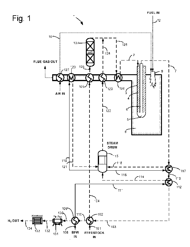
[0023] Figure 1 depicts an example embodiment of a hydrogen
production unit 1.
A mixed feed is conveyed via line 2 to bayonet reformer tube 3, entering the
annulus 4,
flowing to the tip 5, and returning via inner tube 6. The mixed feed is both
heated and
converted to syngas containing hydrogen in the annulus which contains a
catalyst, reaching a
-6-
CA 03165707 2022- 7- 21
WO 2021/150942
PCT/US2021/014691
first temperature at the tip and a second temperature lower than the first
temperature at the
outlet and outlet line 7.
[0024] The reformer tube is at least partially disposed
within a reformer furnace
8. A burner 9 heats the furnace, being supplied with air via line 10, and fuel
via line 12.
[0025] Line 101 conveys a hydrocarbon feedstock to heat
exchanger 102 wherein
the feedstock is preheated against syngas from line 103. The preheated
feedstock is
conveyed by line 104 from heat exchanger 102 to heat exchanger 105 wherein it
is further
heated against combustion products from the furnace to a temperature suitable
for
desulphurization. Line 106 conveys the further heated feedstock from heat
exchanger 105 to
desulphurization unit 107 wherein the feedstock is desulphurized.
[0026] Boiler feed water is conveyed via line 108 to heat
exchanger 109 wherein
it is heated against syngas from line 110. The heated boiler feed water is
conveyed via line
111 from heat exchanger 109 to heat exchanger 112 wherein it is vaporized to
steam against
syngas from line 113. The resultant steam is conveyed by line 114 from heat
exchanger 112
to steam drum 115. The steam drum distributes liquid phase water via line 116
to heat
exchanger 117 wherein it is vaporized against syngas from line 7 and whereupon
the
resultant steam is returned from heat exchanger 117 via line 118 to the steam
drum. The
steam drum also distributes liquid phase water via line 119 to heat exchanger
120 wherein it
is vaporized against combustion products from the furnace and whereupon the
resultant
steam is returned from heat exchanger 120 via line 121 to the steam drum.
[0027] Steam is conveyed from the steam drum via line 122
to heat exchanger
123 wherein it is superheated against combustion products from the furnace.
The
superheated steam is conveyed via line 124 from heat exchanger 123 to line 125
wherein the
superheated steam mixes with the feedstock exiting the desulphurization unit
107 via line
125. Line 125 further conveys the mixed feed to heat exchanger 126 wherein the
mixed feed
is preheated against combustion products from the furnace. The preheated mixed
feed is
conveyed via line 2 from heat exchanger 126 to the bayonet reformer tube.
[0028] Ambient air is inducted into heat exchanger 127
wherein it is preheated
against combustion products from the furnace. The preheated air is conveyed
via line 10
from heat exchanger 127 to the burner wherein it combusts with fuel to heat
the furnace.
-7-
CA 03165707 2022- 7- 21
WO 2021/150942
PCT/US2021/014691
[0029] The syngas exiting the reformer via line 7 is
sequentially cooled in heat
exchanger 117, conveyed via line 113 to heat exchanger 112 wherein it is
further cooled,
conveyed via line 103 to heat exchanger 102 wherein it is cooled against
feedstock, conveyed
via line 110 to heat exchanger 109 wherein it is cooled against boiler feed
water, conveyed
via line 130 to fin fan heat exchanger 131 wherein it is cooled against
ambient air and some
of the steam content of the syngas condenses, conveyed via line 132 to water
knockout unit
133 wherein condensed water is removed from the syngas, and conveyed via line
134 to a
methanol synthesis unit.
[0030] Upon combustion in the furnace, the products of
combustion sequentially
pass through heat exchangers 126, 123, 105, 120, and 127 and finally exit the
hydrogen
production unit.
[0031] The numerals in the figures correspond to equivalent
components of the
various figures.
[0032] Figure 2 illustrates another example embodiment of a
hydrogen
production unit 1. A mixed feed is conveyed via line 2 to single pass reformer
tube 3
containing a suitable catalyst wherein the mixed feed is both heated and
converted to a
syngas containing hydrogen. Syngas exits the tube via outlet line 7.
[0033] The reformer tube is at least partially disposed
within reformer furnace 8.
Recuperative or regenerative burners 9 heat the furnace, being supplied with
air via line 10
and fuel via line 12. The inducted air is preheated in heat exchanger 13
within the burner
against products of combustion from the furnace before the air is combusted
with fuel.
[0034] Preferably, steam line 14 conveys steam to heat
exchanger 15 preferably
within the burner wherein the steam is superheated against combustion products
from the
furnace. The superheated steam is conveyed via line 16 to line 2 wherein the
steam mixes
with mixed feed and is conveyed into the reformer tube.
[0035] Line 101 conveys a hydrocarbon feedstock to heat
exchanger 102 wherein
the feedstock is preheated against syngas from line 103. The preheated
feedstock is
conveyed by line 104 from heat exchanger 102 to heat exchanger 140 wherein it
is further
heated against syngas from line 141 to a temperature suitable for
desulphurization. Line 106
conveys the further heated feedstock from heat exchanger 140 to
desulphurization unit 107
wherein the feedstock is desulphurized.
-8-
CA 03165707 2022- 7- 21
WO 2021/150942
PCT/US2021/014691
[0036] Boiler feed water is conveyed via line 108 to heat
exchanger 109 wherein
it is heated against syngas from line 110. The heated boiler feed water is
conveyed via line
111 from heat exchanger 109 to heat exchanger 142 wherein the water is
vaporized to steam
against syngas from line 7. The resultant steam is conveyed by line 143 from
heat exchanger
142 to line 2 wherein the superheated steam mixes with the feedstock exiting
the
desulphurization unit via line 2. The resultant mixed feed is conveyed via
line 2 to the single
pass reformer tube.
[0037] The syngas exiting the reformer via line 7 is
sequentially cooled in heat
exchanger 142, conveyed via line 141 to heat exchanger 140 wherein it is
further cooled,
conveyed via line 103 to heat exchanger 102 wherein it is cooled, conveyed via
line 110 to
heat exchanger 109 wherein it is cooled, conveyed via line 130 to fin fan heat
exchanger 131
wherein it is cooled against ambient air and some of the steam content of the
syngas
condenses, conveyed via line 132 to water knockout unit 133 wherein condensed
water is
removed from the syngas, and conveyed via line 134 from the knockout unit to a
methanol
synthesis unit.
[0038] Line 14 conveys a second stream of steam from heat
exchanger 142 to
heat exchanger 15.
[0039] Upon exiting the furnace, the products of combustion
sequentially pass
through heat exchangers 15 and 13 wherein they are cooled and finally exit the
hydrogen
production unit I.
[0040] Figure 3 depicts an example embodiment of a hydrogen
production unit 1.
A mixed feed is conveyed via line 2 to bayonet reformer tube 3, entering the
annulus 4,
flowing to the tip 5, and returning via inner tube 6. The mixed feed is both
heated and
converted to syngas containing hydrogen in the annulus which contains a
catalyst, reaching a
first temperature at the tip and a second temperature lower than the first
temperature at the
outlet and outlet line 7.
[0041] The reformer tube is at least partially disposed
within reformer furnace 8.
Recuperative burner 9 heats the furnace, being supplied with air via line 10
and fuel via line
12. The inducted air is preheated in heat exchanger 13 within the regenerative
burner against
products of combustion from the furnace before the air is combusted with fuel.
-9-
CA 03165707 2022- 7- 21
WO 2021/150942
PCT/US2021/014691
[0042] Line 101 conveys a hydrocarbon feedstock to heat
exchanger 102 wherein
the feedstock is preheated against syngas from line 103. The preheated
feedstock is
conveyed by line 104 from heat exchanger 102 to heat exchanger 150 wherein it
is further
heated against syngas from line 151 to a temperature suitable for
desulphurization. Line 106
conveys the further heated feedstock from heat exchanger 150 to
desulphurization unit 107
wherein the feedstock is desulphurized.
[0043] Boiler feed water is conveyed via line 108 to heat
exchanger 109 wherein
it is heated against syngas from line 110. The heated boiler feed water is
conveyed via line
111 from heat exchanger 109 to heat exchanger 142 wherein the water is
vaporized to steam
against syngas from line 7. The resultant steam is conveyed by line 143 from
heat exchanger
142 to heat exchanger 15 within the burner wherein the steam is superheated
against
combustion products from the furnace. The superheated steam is conveyed via
line 16 from
heat exchanger 15 to line 2 wherein the superheated steam mixes with the
feedstock exiting
the desulphurization unit via line 2. The resultant mixed feed is conveyed via
line 2 to the
bayonet reformer tube.
[0044] The syngas exiting the reformer via line 7 is
sequentially cooled in heat
exchanger 142, conveyed via line 151 to heat exchanger 150 wherein it is
further cooled,
conveyed via line 103 to heat exchanger 102 wherein it is cooled, conveyed via
line 110 to
heat exchanger 109 wherein it is cooled, conveyed via line 130 to fin fan heat
exchanger 131
wherein it is cooled against ambient air and some of the steam content of the
syngas
condenses, conveyed via line 132 to water knockout unit 133 wherein condensed
water is
removed from the syngas, and conveyed via line 134 to a methanol synthesis
unit.
[0045] Upon combustion in the furnace, the products of
combustion sequentially
pass through heat exchangers 15 and 13 wherein they are cooled and finally
exit the
hydrogen production unit.
[0046] Figure 4 depicts a methanol production unit 400
consists of a combination
of a steam reforming hydrogen production unit 1 and a methanol synthesis unit.
Syngas
containing hydrogen and carbon monoxide is supplied by line 134 from the steam
reforming
hydrogen production unit 1 and a methanol synthesis unit. The hydrogen
production unit 1
may be any of the units 1 shown in Figures 1,2, or 3.
-10-
CA 03165707 2022- 7- 21
WO 2021/150942
PCT/US2021/014691
[0047] Syngas is conveyed via line 134 from hydrogen
production unit 1 to
compressor 401 wherein the syngas is compressed. The syngas is conveyed by
line 402 from
compressor 401 to compressor 403 wherein the syngas along with recirculated
gas from line
417 is compressed to a pressure suitable for methanol synthesis, such as 150
to 250 bar-g for
example. The fully compressed gas is conveyed via line 404 from compressor 403
to heat
exchanger 405 wherein the compressed gas is heated against methanol bearing
gas from line
406. The heated gas is conveyed via line 407 from heat exchanger 405 to
methanol synthesis
reactor 408 wherein it is exposed to a suitable catalyst and exothermically
reacts to a steam
of higher methanol concentration. The reacted gas is conveyed via line 409
from the reactor
to waste heat boiler 410 wherein it is cooled against boiler feed water,
resulting in the boiler
feed water being vaporized to steam. The cooled reacted gas is conveyed via
line 406 from
boiler 410 to heat exchanger 405 wherein it is further cooled against gas from
line 404. The
further cooled gas is conveyed via line 411 from heat exchanger 405 to heat
exchanger 412
wherein it is cooled against ambient air, some steam condenses, and some
methanol dissolves
in the steam condensate. The resultant gas and liquid are conveyed via line
413 from unit
412 to phase separator 414 wherein the liquid and gas phases are separated.
Liquid water
containing methanol exits the separator via line 416, and some of the
remaining gas is
recirculated via line 417 from the phase separator 414 to line 402 and then to
compressor 403
wherein the recirculated gas is repressurized for recirculation to the
methanol synthesis
reactor. A portion of the gas in line 417 is metered and purged to line 418
for use as fuel in
the furnace of the hydrogen production unit. The gas in line 418 is conveyed
to burners in
the steam reforming unit (shown in Figures 1, 2, and 3) wherein the gas is
combusted as fuel.
[0048] Compressor 401 is driven by driver 431, and
compressor 403 is driven by
driver 433. At least one of drivers 431 and 433 is at least one of a gas
turbine, a steam
turbine utilizing inlet steam at a temperature greater than 550 C and more
preferably greater
than 600 , and most preferably greater than 650 C, a combined cycle gas
turbine and steam
turbine, and an electric motor.
[0049] Although the present technology has been described
in terms of certain
preferred embodiments, various features of separate embodiments can be
combined to form
additional embodiments not expressly described. Moreover, other embodiments
apparent to
those of ordinary skill in the art after reading this disclosure are also
within the scope of this
-11 -
CA 03165707 2022- 7- 21
WO 2021/150942
PCT/US2021/014691
technology. Furthermore, not all the features, aspects and advantages are
necessarily
required to practice the present technology. Thus, while the above detailed
description has
shown, described, and pointed out novel features of the technology as applied
to various
embodiments, it will be understood that various omissions, substitutions, and
changes in the
form and details of the apparatus or process illustrated may be made by those
of ordinary
skill in the technology without departing from the spirit or scope of the
present disclosure.
The technology may be embodied in other specific forms not explicitly
described herein.
The embodiments described above are to be considered in all respects as
illustrative only and
not restrictive in any manner.
-12-
CA 03165707 2022- 7- 21