Note: Descriptions are shown in the official language in which they were submitted.
CA 03166089 2022-06-27
WO 2021/136616
PCT/EP2020/082297
ACHROMATIC LENSES FOR VISION TREATMENT
CROSS REFERENCE TO RELATED APPLICATIONS
[0001] This application claims priority to U.S. Provisional Patent Application
No. 62/955341,
.. filed on December 30, 2019, the entire contents of which are hereby
incorporated by reference.
BACKGROUND
[0002] Embodiments of the present disclosure relate to vision treatment
techniques and in
particular, to ophthalmic lenses such as, for example, contact lenses, corneal
inlays or onlays, or
intraocular lenses (IOLs) including, for example, phakic IOLs and piggyback
IOLs (i.e. IOLs
implanted in an eye already having an IOL).
[0003] Presbyopia is a condition that affects the accommodation properties of
the eye. As
objects move closer to a young, properly functioning eye, the effects of
ciliary muscle contraction
and zonular relaxation allow the lens of the eye to change shape, and thus
increase its optical power
and ability to focus at near distances. This accommodation can allow the eye
to focus and refocus
.. between near and far objects.
[0004] Presbyopia normally develops as a person ages and is associated with a
natural
progressive loss of accommodation. The presbyopic eye often loses the ability
to rapidly and
easily refocus on objects at varying distances. The effects of presbyopia
usually become noticeable
after the age of 45 years. By the age of 65 years, the crystalline lens has
often lost almost all elastic
properties and has only a limited ability to change shape.
[0005] Along with reductions in accommodation of the eye, age may also induce
clouding of
the lens due to the formation of a cataract. A cataract may form in the hard
central nucleus of the
lens, in the softer peripheral cortical portion of the lens, or at the back of
the lens. Cataracts can
be treated by the replacement of the cloudy natural lens with an artificial
lens. An artificial lens
replaces the natural lens in the eye, with the artificial lens often being
referred to as an intraocular
lens or
[0006] Monofocal IOLs are intended to provide vision correction at one
distance only, usually
the far focus. At the very least, since a monofocal IOL provides vision
treatment at only one
CA 03166089 2022-06-27
WO 2021/136616
PCT/EP2020/082297
distance and since the typical correction is for far distance, spectacles are
usually needed for good
vision at near distances and sometimes for good vision at intermediate
distances. The term "near
vision" generally corresponds to vision provided when objects are at a
distance from the subject
eye at equal; or less than 1.5 feet. The term "distant vision" generally
corresponds to vision
provided when objects are at a distance of at least about 5-6 feet or greater.
The term "intermediate
vision" corresponds to vision provided when objects are at a distance of about
1.5 feet to about 5-
6 feet from the subject eye. Such characterizations of near, intermediate, and
far vision correspond
to those addressed in Morlock R, Wirth RJ, Tally SR, Garufis C, Heichel CWD,
Patient-Reported
Spectacle Independence Questionnaire (PRSIQ): Development and Validation.
Am J
Ophthalmology 2017; 178:101-114.
[0007] There have been various attempts to address limitations associated with
monofocal IOLs.
For example, multifocal IOLs have been proposed that deliver, in principle,
two foci, one near and
one far, optionally with some degree of intermediate focus. Such multifocal,
or bifocal, IOLs are
intended to provide good vision at two distances, and include both refractive
and diffractive
multifocal IOLs. In some instances, a multifocal IOL intended to correct
vision at two distances
may provide a near (add) power of about 3.0 or 4.0 diopters.
[0008] Multifocal IOLs may, for example, rely on a diffractive optical surface
to direct portions
of the light energy toward differing focal distances, thereby allowing the
patient to clearly see both
near and far objects. Multifocal ophthalmic lenses (including contact lenses
or the like) have also
been proposed for treatment of presbyopia without removal of the natural
crystalline lens.
Diffractive optical surfaces, either monofocal or multifocal, may also be
configured to provide
reduced chromatic aberration.
[0009] Diffractive monofocal and multifocal lenses can make use of a material
having a given
refractive index and a surface curvature which provide a refractive power.
Diffractive lenses have
a diffractive profile which confers the lens with a diffractive power that
contributes to the overall
optical power of the lens. The diffractive profile is typically characterized
by a number of
diffractive zones. When used for ophthalmic lenses these zones are typically
annular lens zones,
or echelettes, spaced about the optical axis of the lens. Each echelette may
be defined by an optical
zone, a transition zone between the optical zone and an optical zone of an
adjacent echelette, and
an echelette geometry. The echelette geometry includes an inner and outer
diameter and a shape
2
CA 03166089 2022-06-27
WO 2021/136616
PCT/EP2020/082297
or slope of the optical zone, a height or step height, and a shape of the
transition zone. The surface
area or diameter of the echelettes largely determines the diffractive power(s)
of the lens and the
step height of the transition between echelettes largely determines the light
distribution between
the different powers. Together, these echelettes form a diffractive profile.
[0010] A multifocal diffractive profile of the lens may be used to mitigate
presbyopia by
providing two or more optical powers; for example, one for near vision and one
for far vision. The
lenses may also take the form of an intraocular lens placed within the
capsular bag of the eye,
replacing the original lens, or placed in front of the natural crystalline
lens. The lenses may also
be in the form of a contact lens, most commonly a bifocal contact lens, or in
any other form
mentioned herein.
[0011] Although multifocal ophthalmic lenses lead to improved quality of
vision for many
patients, additional improvements would be beneficial. For example, some
pseudophakic patients
experience undesirable visual effects (dysphotopsia), e.g. glare or halos.
Halos may arise when
light from the unused focal image creates an out-of-focus image that is
superimposed on the used
.. focal image. For example, if light from a distant point source is imaged
onto the retina by the
distant focus of a bifocal IOL, the near focus of the IOL will simultaneously
superimpose a
defocused image on top of the image formed by the distant focus. This
defocused image may
manifest itself in the form of a ring of light surrounding the in-focus image,
and is referred to as a
halo. Another area of improvement revolves around the typical bifocality of
multifocal lenses.
.. While multifocal ophthalmic lenses typically provide adequate near and far
vision, intermediate
vision may be compromised.
[0012] Improvements may also be found in the field of achromats. Achromatic
lenses may be
utilized to improve color contrast of a lens, however, if such achromats are
provided as diffractive
patterns then undesired visual effects may result, such as glare or halos.
Improvements in lenses
having achromats are thus desired.
BRIEF SUMMARY
[0013] Embodiments herein described include ophthalmic lenses including an
optic having a
central region disposed about an optical axis and a peripheral region
extending outward from the
central region, with a diffractive achromat positioned on the peripheral
region, and the central
3
CA 03166089 2022-06-27
WO 2021/136616
PCT/EP2020/082297
region lacking an achromat, and a base power for distance of the central
region being the same as
a base power for distance of the peripheral region.
[0014] The optic may include a transition between the central region and the
peripheral region
at which a base curvature of the optic changes. The central region may be
adjacent to the peripheral
region. The base power for distance of the peripheral region may have a
distance power of the
diffractive achromat combined with a distance refractive power of the
peripheral region. The optic
may also extends outward from the optical axis to an outer periphery of the
optic, and a base power
for distance of the optic may be the same from the optical axis to the outer
periphery of the optic.
[0015] The central region may be a refractive region, and the base power for
distance of the
central region may be a refractive power. The central region may extend
outward from the optical
axis to a radius of at least 1 millimeter, of at least 1.5 millimeters, or of
at least 2 millimeters. The
central region in other embodiments may comprise an extended depth of focus
diffractive region,
or utilize bifocality, trifocality, or aperiodic designs (or may be a
refractive extended depth of
focus region).
[0016] Embodiments herein described include a method including fabricating an
optic for an
ophthalmic lens, the optic having a central region disposed about an optical
axis and a peripheral
region extending outward from the central region, with a diffractive achromat
positioned on the
peripheral region, and the central region lacking an achromat, and a base
power for distance of the
central region being the same as a base power for distance of the peripheral
region.
[0017] The method may include receiving an ophthalmic lens prescription, and
fabricating the
optic based on the ophthalmic lens prescription. The method may include
determining a profile
of one or more of the central region or the diffractive achromat based on the
ophthalmic lens
prescription. The base power for distance of the peripheral region may
comprise a distance power
of the diffractive achromat combined with a distance refractive power of the
peripheral region.
This method of fabrication may be used to fabricate any lens disclosed herein.
[0018] Embodiments herein described include a system for fabricating an
ophthalmic lens. The
system may include a processor configured to determine at least a portion of a
profile of an optic
having a central region disposed about an optical axis and a peripheral region
extending outward
from the central region, with a diffractive achromat positioned on the
peripheral region, and the
4
CA 03166089 2022-06-27
WO 2021/136616
PCT/EP2020/082297
central region lacking an achromat, and a base power for distance of the
central region being the
same as a base power for distance of the peripheral region. The system may
include a
manufacturing assembly that fabricates the optic based on the profile.
[0019] The system may further include an input for receiving an ophthalmic
lens prescription,
.. and the processor may be configured to determine a profile of one or more
of the central region or
the diffractive achromat based on the ophthalmic lens prescription. The base
power for distance
of the peripheral region may comprise a distance power of the diffractive
achromat combined with
a distance refractive power of the peripheral region. The optic extends
outward from the optical
axis to an outer periphery of the optic, and a base power for distance of the
optic is the same from
the optical axis to the outer periphery of the optic. This system for
fabricating may be used to
fabricate any lens disclosed herein.
BRIEF DESCRIPTION OF THE DRAWINGS
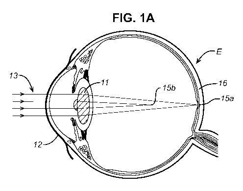
[0020] FIG. 1A illustrates a cross-sectional view of an eye with an implanted
multifocal
refractive intraocular lens.
[0021] FIG. 1B illustrates a cross-sectional view of an eye having an
implanted multifocal
diffractive intraocular lens.
[0022] FIG. 2A illustrates a front view of a diffractive multifocal
intraocular lens.
[0023] FIG. 2B illustrates a cross-sectional view of a diffractive multifocal
intraocular lens.
[0024] FIGS. 3A-3B are graphical representations of a portion of the
diffractive profile of a
conventional diffractive multifocal lens.
[0025] FIG. 4 illustrates a diffractive profile of a diffractive achromat.
[0026] FIG. 5 illustrates an embodiment of an optic including a central region
disposed about an
optical axis and having a peripheral region extending outward from the central
region.
[0027] FIG. 6 illustrates a chart of through frequency modulation transfer
function (MTF) for
an optic that does not include an achromat.
[0028] FIG. 7 illustrates a chart of through frequency MIT for an optic that
includes an achromat
along the entire optical surface.
5
CA 03166089 2022-06-27
WO 2021/136616
PCT/EP2020/082297
[0029] FIG. 8 illustrates a chart of through frequency MTF for an optic that
includes a central
region and a diffractive achromat on a peripheral region.
[0030] FIG. 9 illustrates a chart of point spread function (PSF) of the optic
of FIG. 7.
[0031] FIG. 10 illustrates a chart of point spread function (PSF) of the optic
of FIG. 8.
[0032] FIG. 11 illustrates an embodiment of a system.
DETAILED DESCRIPTION
[0033] FIGS. 1A, 1B, 2A, 2B, 3A and 3B illustrate multifocal IOL lens
geometries, aspects of
which are described in U.S. Patent Publication No. 2011-0149236 Al, which is
hereby
incorporated by reference in its entirety.
[0034] FIG. lA is a cross-sectional view of an eye E fit with a multifocal IOL
11. As shown,
multifocal IOL 11 may, for example, comprise a bifocal IOL. Multifocal IOL 11
receives light
from at least a portion of cornea 12 at the front of eye E and is generally
centered about the optical
axis of eye E. For ease of reference and clarity, FIGS. 1A and 1B do not
disclose the refractive
properties of other parts of the eye, such as the corneal surfaces. Only the
refractive and/or
diffractive properties of the multifocal IOL 11 are illustrated.
[0035] Each major face of lens 11, including the anterior (front) surface and
posterior (back)
surface, generally has a refractive profile, e.g. biconvex, plano-convex,
plano-concave, meniscus,
etc. The two surfaces together, in relation to the properties of the
surrounding aqueous humor,
cornea, and other optical components of the overall optical system, define the
effects of the lens
11 on the imaging performance by eye E. Conventional, monofocal IOLs have a
refractive power
based on the refractive index of the material from which the lens is made, and
also on the curvature
or shape of the front and rear surfaces or faces of the lens. One or more
support elements may be
configured to secure the lens 11 to a patient's eye.
[0036] Multifocal lenses may optionally also make special use of the
refractive properties of the
lens. Such lenses generally include different powers in different regions of
the lens so as to
mitigate the effects of presbyopia. For example, as shown in FIG. 1A, a
perimeter region of
refractive multifocal lens 11 may have a power which is suitable for viewing
at far viewing
distances. The same refractive multifocal lens 11 may also include an inner
region having a higher
6
CA 03166089 2022-06-27
WO 2021/136616
PCT/EP2020/082297
surface curvature and a generally higher overall power (sometimes referred to
as a positive add
power) suitable for viewing at near distances.
[0037] Rather than relying entirely on the refractive properties of the lens,
multifocal diffractive
IOLs or contact lenses can also have a diffractive power, as illustrated by
the IOL 18 shown in
FIG. 1B. The diffractive power can, for example, comprise positive or negative
power, and that
diffractive power may be a significant (or even the primary) contributor to
the overall optical
power of the lens. The diffractive power is conferred by a plurality of
concentric diffractive zones
which form a diffractive profile. The diffractive profile may either be
imposed on the anterior face
or posterior face or both.
[0038] The diffractive profile of a diffractive multifocal lens directs
incoming light into a
number of diffraction orders. As light 13 enters from the front of the eye,
the multifocal lens 18
directs light 13 to form a far field focus 15a on retina 16 for viewing
distant objects and a near
field focus 15b for viewing objects close to the eye. Depending on the
distance from the source
of light 13, the focus on retina 16 may be the near field focus 15b instead.
Typically, far field
focus 15a is associated with 0th diffractive order and near field focus 15b is
associated with the 1'
diffractive order, although other orders may be used as well.
[0039] Bifocal ophthalmic lens 18 typically distributes the majority of light
energy into two
viewing orders, often with the goal of splitting imaging light energy about
evenly (50%:50%), one
viewing order corresponding to far vision and one viewing order corresponding
to near vision,
although typically, some fraction goes to non-viewing orders.
[0040] Corrective optics may be provided by phakic IOLs, which can be used to
treat patients
while leaving the natural lens in place. Phakic IOLs may be angle supported,
iris supported, or
sulcus supported. The phakic IOL can be placed over the natural crystalline
lens or piggy-backed
over another IOL. It is also envisioned that the present disclosure may be
applied to inlays, onlays,
accommodating IOLs, pseudophakic IOLs, other forms of intraocular implants,
spectacles, and
even laser vision correction.
[0041] FIGS. 2A and 2B show aspects of a conventional diffractive multifocal
lens 20.
Multifocal lens 20 may have certain optical properties that are generally
similar to those of
multifocal IOLs 11, 18 described above. Multifocal lens 20 has an anterior
lens face 21 and a
7
CA 03166089 2022-06-27
WO 2021/136616
PCT/EP2020/082297
posterior lens face 22 disposed about an optical axis 24. The faces 21, 22, or
optical surfaces,
extend radially outward from the optical axis 24 to an outer periphery 27 of
the optic. The faces
21, 22, or optical surfaces, face opposite each other.
[0042] When fitted onto the eye of a subject or patient, the optical axis of
lens 20 is generally
aligned with the optical axis of eye E. The curvature of lens 20 gives lens 20
an anterior refractive
profile and a posterior refractive profile. Although a diffractive profile may
also be imposed on
either anterior face 21 and posterior face 22 or both, FIG. 2B shows posterior
face 22 with a
diffractive profile. The diffractive profile is characterized by a plurality
of annular diffractive
zones or echelettes 23 spaced about optical axis 24. While analytical optics
theory generally
assumes an infinite number of echelettes, a standard multifocal diffractive
IOL typically has at
least 9 echelettes, and may have over 30 echelettes. For the sake of clarity,
FIG. 2B shows only 4
echelettes. Typically, an IOL is biconvex, or possibly plano-convex, or convex-
concave, although
an IOL could be plano-plano, or other refractive surface combinations.
[0043] FIGS. 3A and 3B are graphical representations of a portion of a typical
diffractive profile
of a multifocal lens. While the graph shows only 3 echelettes, typical
diffractive lenses extend to
at least 9 echelettes to over 32 echelettes. In FIG. 3A, the height 32 of the
surface relief profile
(from a plane perpendicular to the light rays) of each point on the echelette
surface is plotted
against the square of the radial distance (r2 or p) from the optical axis of
the lens (referred to as r-
squared space). In multifocal lenses, each echelette 23 may have a diameter or
distance from the
optical axis which is often proportional to In, n being the number of the
echelette 23 as counted
from optical axis 24. Each echelette has a characteristic optical zone 30 and
transition zone 31.
Optical zone 30 typically has a shape or downward slope that is parabolic as
shown in FIG. 3B.
The slope of each echelette in r-squared space (shown in FIG. 3A), however, is
the same. As for
the typical diffractive multifocal lens, as shown here, all echelettes have
the same surface area.
The area of echelettes 23 determines the diffractive power of lens 20, and, as
area and radii are
correlated, the diffractive power is also related to the radii of the
echelettes. The physical offset
of the trailing edge of each echelette to the leading edge of the adjacent
echelette is the step height.
An exemplary step height between adjacent echelettes is marked as reference
number 33 in FIG.
3A. The step heights remain the same in r-squared space (FIG. 3A) and in
linear space (FIG. 3B).
The step offset is the height offset of the transition zone from the
underlying base curve.
8
CA 03166089 2022-06-27
WO 2021/136616
PCT/EP2020/082297
[0044] Diffractive profiles may be utilized to provide multifocality of lenses
and may be utilized
to correct chromatic aberrations. A diffractive achromat, including a
diffractive profile, may be
utilized with an optic to reduce chromatic aberrations. FIG. 4, for example,
illustrates a diffractive
profile of a diffractive achromat. The diffractive profile 400 of the
diffractive achromat is shown
relative to the Y axis 402, which represents the phase shift of the
diffractive profile 400. The
height is shown in units of millimeters (mm), and may represent the distance
from the base
spherical wavefront generated by the lens. In other embodiments, other units
or scalings may be
utilized. The height or phase shift of the diffractive profile 400 is shown in
relation to the radius
on the X axis 404 from the optical axis 406 in r-squared space. The radial
coordinate represents
the distance from the optical axis 406 in r-squared space, and is shown in
units of millimeters
squared, although in other embodiments, other units or scalings may be
utilized.
[0045] The diffractive profile 400 of the diffractive achromat includes a
repeating pattern of
echelettes (representative echelettes 408a, 408b, 408c are marked) that each
have the same width
in r-squared space. The step height of each echelette is also the same in the
diffractive profile 400.
.. Notably, the diffractive profile 400 of the diffractive achromat extends
along the entirety of the
optic, extending outward from the optical axis 406 towards the outer periphery
of the optic. The
entire optic may have the same base curvature, which may be reduced for the
entirety of the optic
to compensate for the additional optical power of the diffractive achromat.
[0046] FIG. 5 illustrates an embodiment of an optic including a central region
500 disposed
about an optical axis 502 and having a peripheral region 504 extending outward
from the central
region 500. The central region 500 may lack an achromat. A diffractive
achromat having a
diffractive profile 506 may be positioned on the peripheral region 504 and may
extend outward
from the central region 500. The base power for distance of the central region
500 may be the
same as a base power for distance of the peripheral region 504. In regard to
the diffractive profile
506, the diffractive profile 506 is shown relative to the Y axis 508, which
represents the phase shift
of the diffractive profile 506. The height is shown in units of millimeters
(mm), and may represent
the distance from the base spherical wavefront generated by the lens. In other
embodiments, other
units or scalings may be utilized. The height or phase shift of the
diffractive profile 506 is shown
in relation to the radius on the X axis 510 from the optical axis 502 in r-
squared space. The radial
coordinate represents the distance from the optical axis 502 in r-squared
space, and is shown in
9
CA 03166089 2022-06-27
WO 2021/136616
PCT/EP2020/082297
units of millimeters squared, although in other embodiments, other units or
scalings may be
utilized.
[0047] The diffractive profile 506 of the diffractive achromat may be
configured similarly as the
diffractive profile 400 shown in FIG. 4, and may comprise a plurality of
echelettes. The echelettes
may repeat on the peripheral region 504 and may have the same width in r-
squared space and step
height, although in other embodiments other configurations may be utilized.
The diffractive
profile 506 of the diffractive achromat may extend outward from a transition
512 with the central
region 500 to the outer periphery of the optic. In other embodiments, the
diffractive profile of the
diffractive achromat may extend for another radial distance as desired.
[0048] The central region 500 may include the portion of the optic that the
optical axis 502
extends through and may extend outward from the optical axis 502 to a desired
radial distance. In
certain embodiments, the distance may be to about 1.4 millimeters or to a
greater or lesser radius
as desired (e.g., 1 millimeter, 1.25 millimeters, 1.5 millimeters, 1.75
millimeters, 2 millimeters,
among others). The distance may be at least 1 millimeter, at least 1.5
millimeters, or at least 2
millimeters, among other lesser or greater distances. The central region 500
may be adjacent to
the peripheral region 504. An achromat, diffractive achromat, or other
diffractive profile is not
positioned on the central region 500. The central region may be configured to
correct ocular
aberrations of the patient's eye, including spherical optical aberrations
among others. The
diffractive achromat positioned on the peripheral region 504 may be configured
to correct
longitudinal chromatic aberrations.
[0049] The base curvature of the optic may be configured such that the base
curvature of the
central region 500 is greater than the base curvature of the peripheral region
504. The base
curvature of the optic is reduced in a direction outward from the optical axis
502 at the transition
512. The base curvature of the central region 500 may be greater than the base
curvature of the
peripheral region 504 such that the optic has the same base power for distance
across the central
region 500 and the peripheral region 504 including the diffractive profile 506
of the diffractive
achromat. The base power for distance of the peripheral region 504 may
comprise a distance
power of the diffractive achromat combined with a distance refractive power of
the peripheral
region 504. The base power for distance of the optic may be the same from the
optical axis 502 to
the outer periphery of the optic.
CA 03166089 2022-06-27
WO 2021/136616
PCT/EP2020/082297
[0050] The presence of the central region 500 may account for the dilation and
contraction of
the patient's pupil to provide desired optical effects. When the pupil is
contracted and small, the
radius of the central region 500 may be set such that light only passes
through the central region
500, to reduce the possibility of glare or other adverse optical effects that
may be caused by the
diffractive achromat. However, when the pupil is dilated and large, light may
be provided upon
the diffractive achromat, to allow for greater color contrast (which may be at
night when the need
for color contrast is highest).
[0051] The central region 500 may be a refractive region. The base power for
distance of the
central region 500 may be a refractive power. The central region 500 in other
embodiments may
comprise an extended depth of focus diffractive region or utilize bifocality,
trifocality, aperiodic
designs (or may be a refractive extended depth of focus region). Extended
depth of focus or
multifocality features (which may include a diffractive profile) may be
applied to the central region
500 or to the entire optic as desired.
[0052] FIG. 6 illustrates a chart of through frequency modulation transfer
function (MTF) for
an optic that does not include an achromat. MIT is shown on the Y axis 600,
and frequency is
shown on the X axis 602. FIG. 7 illustrates a chart of through frequency MIT
for an optic that
includes an achromat along the entire optical surface, similar to an
embodiment shown in FIG. 4.
MTF is shown on the Y axis 700, and frequency is shown on the X axis 702.
[0053] FIG. 8 illustrates a chart of through frequency MTF for an optic that
includes a central
.. region and a diffractive achromat on a peripheral region, for example as
shown in FIG. 5. MTF is
shown on the Y axis 800, and frequency is shown on the X axis 802. The MTF for
an embodiment
as shown in FIG. 5 is shown to preserve most of the contrast gain. However,
with reference to
FIGS. 9 and 10, which show scatter (point spread function), the embodiment
shown in FIG. 5 will
have lower incidences of visual symptoms than an embodiment as shown in FIG.
4.
[0054] FIG. 9 illustrates point spread function (PSF) with PSF shown on the Y
axis 900 and
angle shown on the X axis 902. The PSF is of an embodiment as shown in FIG. 7.
The cliff 904
in the profile represents a risk of visual symptoms. FIG. 10 illustrates point
spread function (PSF)
with PSF shown on the Y axis 1000 and angle shown on the X axis 1002 for an
embodiment as
shown in FIG. 8. The presence of the cliff is reduced, representing lower risk
of visual symptoms
for the embodiment shown in FIG. 8 than the embodiment shown in FIG. 7.
11
CA 03166089 2022-06-27
WO 2021/136616
PCT/EP2020/082297
[0055] An optic for an ophthalmic lens that includes a profile (both the
profile of the central
region and/or the profile of the diffractive achromat) disclosed herein may be
fabricated utilizing
a variety of methods. A method may include determining optical aberrations of
a patient's eye.
Measurements of a patient's eye may be made in a clinical setting, such as by
an optometrist,
ophthalmologist, or other medical or optical professional. The measurements
may be made via
manifest refraction, autorefraction, tomography, or a combination of these
methods or other
measurement methods. The optical aberrations of the patient's eye may be
determined. Physical
characteristics of the patient's eye may also be measured, such as pupil size
and dilated and
contracted sizes of the pupil may also be determined.
[0056] The measurements of the patient's eye may be placed in an ophthalmic
lens prescription,
which includes features of an optic that are intended to address the optical
aberrations of the
patient's eye, as well as features that address the pupillary size (including
dilated and contracted
sizes) of the patient.
[0057] The ophthalmic lens prescription may be utilized to fabricate an optic
for the ophthalmic
lens. A refractive profile of the central region of the optic may be
determined based on the
ophthalmic lens prescription, to correct for the optical aberrations of the
patient's eye. Such a
refractive profile may be applied to the optic. The desired diffractive
profile of the diffractive
achromat may also be determined. The power of the diffractive achromat may be
determined, and
the base curvature of the peripheral region having the diffractive achromat
may be reduced such
that the optic has the same base power for distance in the central region and
the peripheral region.
The pupillary size of the patient may be utilized to determine a size (radius)
of the central region
from the optical axis.
[0058] The determination of a profile of one or more of the central region or
the diffractive
achromat and the fabrication of the optic may be performed remotely from the
optometrist,
ophthalmologist, or other medical or optical professional that performed the
measurements of a
patient's eye, or may be performed in the same clinical facility of such an
individual. If performed
remotely, the fabricated optic may be delivered to an optometrist,
ophthalmologist, or other
medical or optical professional, for being provided to a patient. For an
intraocular lens, the
fabricated optic may be provided for implant into a patient's eye.
12
CA 03166089 2022-06-27
WO 2021/136616
PCT/EP2020/082297
[0059] The fabricated optic may be a custom optic fabricated specifically for
the patient's eye,
or may be fabricated in a manufacturing assembly and then selected by an
optometrist,
ophthalmologist, or other medical or optical professional for supply to a
patient, which may
include implantation in the patient's eye.
[0060] FIG. 11 illustrates an embodiment of a system 1100 that may be
utilized to perform all
or a portion of the methods disclosed herein. The system 1100 may include a
processor 1102, an
input 1104, and a memory 1106. In certain embodiments the system 1100 may
include a
manufacturing assembly 1108.
[0061] The processor 1102 may comprise a central processing unit (CPU)
or other form of
processor. In certain embodiments the processor 1102 may comprise one or more
processors. The
processor 1102 may include one or more processors that are distributed in
certain embodiments,
for example, the processor 1102 may be positioned remote from other components
of the system
1100 or may be utilized in a cloud computing environment. The memory 1106 may
comprise a
memory that is readable by the processor 1102. The memory 1106 may store
instructions, or
features of intraocular lenses, or other parameters that may be utilized by
the processor 1102 to
perform the methods disclosed herein. The memory 1106 may comprise a hard
disk, read-only
memory (ROM), random access memory (RAM) or other form of non-transient medium
for
storing data. The input 1104 may comprise a port, terminal, physical input
device, or other form
of input. The port or terminal may comprise a physical port or terminal or an
electronic port or
terminal. The port may comprise a wired or wireless communication device in
certain
embodiments. The physical input device may comprise a keyboard, touchscreen,
keypad, pointer
device, or other form of physical input device. The input 1104 may be
configured to provide an
input to the processor 1102.
[0062] The system 1100 may be utilized to perform the methods disclosed
herein, such as the
processes of determining a profile of one or more of the central region or the
diffractive achromat.
[0063] The processor 1102 may provide the profile of one or more of the
central region or the
diffractive achromat to the manufacturing assembly 1108, which may be
configured to fabricate
the optic for the ophthalmic lens based on the profile of one or more of the
central region or the
diffractive achromat. The manufacturing assembly 1108 may comprise one or more
apparatuses
.. for forming the optic, and may comprise a high volume manufacturing
assembly or a low volume
13
CA 03166089 2022-06-27
WO 2021/136616
PCT/EP2020/082297
manufacturing assembly. The manufacturing assembly 1108 may be used for
manufacture remote
to a clinic in which measurements of the individual's eye or made, or local to
such a clinic. The
manufacturing assembly may include apparatuses such as lathe tools, or other
lens formation
devices to fabricate the optic.
[0064] In one embodiment, the processor 1102 may be provided with an
ophthalmic lens
prescription for the individual's eye that may be provided as discussed
herein. The processor 1102
may receive the ophthalmic lens via the input 1104. The system 1100 may
fabricate the optic for
the ophthalmic lens based on the prescription.
[0065] The system 1100 may be configured to fabricate any of the
embodiments of ophthalmic
lenses disclosed herein.
[0066] In one embodiment, a profile as shown in FIG. 5 may be positioned on a
surface of a lens
that is opposite an aspheric surface. The aspheric surface on the opposite
side of the lens may be
designed to reduce corneal spherical aberration of the patient.
[0067] In one embodiment, one or both surfaces of the lens may be aspherical,
or include a
refractive surface designed to extend the depth of focus, or create
multifocality.
[0068] Any of the embodiments of lens profiles discussed herein may be
apodized to produce a
desired result. The apodization may result in the step heights and step
offsets of the echelettes
being gradually varied according to the apodization, as to gradually
increasing the amount of light
in the distance focus as a function of pupil diameter.
[0069] The features of the optics disclosed herein may be utilized by
themselves, or in
combination with refractive profiles of the optics and/or with other features
providing for
correction of chromatic aberrations.
[0070] The ophthalmic lenses disclosed herein in the form of intraocular
lenses are not limited
to lenses for placement in the individual's capsular bag. For example, the
intraocular lenses may
comprise those positioned within the anterior chamber of the eye. In certain
embodiments the
intraocular lenses may comprise "piggy back" lenses or other forms of
supplemental intraocular
lenses.
[0071] Features of embodiments may be modified, substituted, excluded,
or combined as
14
CA 03166089 2022-06-27
WO 2021/136616
PCT/EP2020/082297
desired.
[0072] In addition, the methods herein are not limited to the methods
specifically described,
and may include methods of utilizing the systems and apparatuses disclosed
herein.
[0073] In closing, it is to be understood that although aspects of the
present specification are
.. highlighted by referring to specific embodiments, one skilled in the art
will readily appreciate that
these disclosed embodiments are only illustrative of the principles of the
subject matter disclosed
herein. Therefore, it should be understood that the disclosed subject matter
is in no way limited to
a particular methodology, protocol, and/or reagent, etc., described herein. As
such, various
modifications or changes to or alternative configurations of the disclosed
subject matter can be
made in accordance with the teachings herein without departing from the spirit
of the present
specification. Lastly, the terminology used herein is for the purpose of
describing particular
embodiments only, and is not intended to limit the scope of systems,
apparatuses, and methods as
disclosed herein, which is defined solely by the claims. Accordingly, the
systems, apparatuses, and
methods are not limited to that precisely as shown and described.
[0074] Certain embodiments of systems, apparatuses, and methods are
described herein,
including the best mode known to the inventors for carrying out the same. Of
course, variations
on these described embodiments will become apparent to those of ordinary skill
in the art upon
reading the foregoing description. The inventor expects skilled artisans to
employ such variations
as appropriate, and the inventors intend for the systems, apparatuses, and
methods to be practiced
otherwise than specifically described herein. Accordingly, the systems,
apparatuses, and methods
include all modifications and equivalents of the subject matter recited in the
claims appended
hereto as permitted by applicable law. Moreover, any combination of the above-
described
embodiments in all possible variations thereof is encompassed by the systems,
apparatuses, and
methods unless otherwise indicated herein or otherwise clearly contradicted by
context.
[0075] Groupings of alternative embodiments, elements, or steps of the
systems, apparatuses,
and methods are not to be construed as limitations. Each group member may be
referred to and
claimed individually or in any combination with other group members disclosed
herein. It is
anticipated that one or more members of a group may be included in, or deleted
from, a group for
reasons of convenience and/or patentability. When any such inclusion or
deletion occurs, the
specification is deemed to contain the group as modified thus fulfilling the
written description of
CA 03166089 2022-06-27
WO 2021/136616
PCT/EP2020/082297
all Markush groups used in the appended claims.
[0076] The terms "a," "an," "the" and similar referents used in the
context of describing the
systems, apparatuses, and methods (especially in the context of the following
claims) are to be
construed to cover both the singular and the plural, unless otherwise
indicated herein or clearly
contradicted by context. All methods described herein can be performed in any
suitable order
unless otherwise indicated herein or otherwise clearly contradicted by
context. The use of any and
all examples, or exemplary language (e.g., "such as") provided herein is
intended merely to better
illuminate the systems, apparatuses, and methods and does not pose a
limitation on the scope of
the systems, apparatuses, and methods otherwise claimed. No language in the
present specification
should be construed as indicating any non-claimed element essential to the
practice of the systems,
apparatuses, and methods.
[0077] All patents, patent publications, and other publications
referenced and identified in the
present specification are individually and expressly incorporated herein by
reference in their
entirety for the purpose of describing and disclosing, for example, the
compositions and
methodologies described in such publications that might be used in connection
with the systems,
apparatuses, and methods. These publications are provided solely for their
disclosure prior to the
filing date of the present application. Nothing in this regard should be
construed as an admission
that the inventors are not entitled to antedate such disclosure by virtue of
prior invention or for any
other reason. All statements as to the date or representation as to the
contents of these documents
is based on the information available to the applicants and does not
constitute any admission as to
the correctness of the dates or contents of these documents.
16