Note: Descriptions are shown in the official language in which they were submitted.
CA 03167232 2022-07-07
WO 2021/154875 PCT/US2021/015318
ADVANCED ROTATING TENSION LATCH
CROSS-REFERENCE TO RELATED APPLICATION
[0001] This application claims priority to U.S. Provisional Application
Serial No.
62/966,403, filed on January 27, 2020, entitled "ROTATING TENSION LATCH AND
APPLICATION THEREOF," U.S. Provisional Application Serial No. 63/024,680,
filed on May
14,2020, entitled "ROTATING TENSION LATCH AND APPLICATION THEREOF," and U.S.
Provisional Application Serial No. 63/039,084, filed on June 15, 2020,
entitled "ROTATING
TENSION LATCH AND APPLICATION THEREOF," all of which are commonly assigned
with
this application and incorporated herein by reference in their entirety.
TECHNICAL FIELD
[0002] This application is directed, in general, to a coupling device or
latch and, more
specifically, to an advanced rotating tension latch.
BACKGROUND
[0003] Fasteners are ubiquitous. A quick trip to the hardware section of
any home center
will readily reveal the broad selection of fasteners. Screws, bolts, rivets,
wall anchors, cotter pins,
magnets, latches, etc., serve to enable one object to be fastened permanently
or temporarily to
another object. Seemingly, the choices are so broad that there is likely a
specific fastener for every
specific application.
[0004] Many assembly line operations use fasteners, such as bolts or
screws, to couple two
separate parts together. However, in many automated assembly line operations
it is desirable to
grasp an assembly with a robotic arm and temporarily relocate the assembly to
the next station
where assembly continues. In some applications magnetic or vacuum forces are
employed to grasp
the assembly for transport. However, in some applications magnetic forces may
be undesirable
because of the nature of the assembly which may be adversely affected by
magnetism. Similarly,
other assemblies may be unsuitable for the use of vacuum force because of
insufficient area to
affect a secure grasp of the assembly, excessive weight of the workpiece, etc.
[0005] In addition, online marketing companies and many of the world's
largest package
delivery services (Amazon, UPS, DHL, Dominos, etc.) are spending heavily to
advance
autonomous, drone-based package delivery. As a result, there are numerous
working prototypes
currently in existence. These prototypes vary widely in where they carry their
payloads, how they
collect and drop off these payloads, in overall design of the drone, and more.
For example, where
Amazon Prime Air employs an anchor-dependent (e.g., the package is coupled
directly to the
drone) delivery drone, Wing employs a tether-dependent delivery drone.
[0006] The current methods of drone delivery in the market have several
limitations. For
example, drones have not been able to pick up packages without the assistance
of human workers
or intricate external automated devices, which makes it difficult to fully
automate the drone
delivery process and therefore reduces delivery cost efficiency. The hardware
and components
required to operate actuators add to the weight of the drone and complicate
the process of loading
the package onto the drone. Delivery range is limited by the additional weight
and energy costs of
these designs, and drop-off locations are limited by the capabilities of the
type of drop-off system
used. Furthermore, if manual loading and unloading is required, delivery times
are limited by the
availability and location of any customer receiving a package. A system that
allows fully
automated loading and unloading in a wider range of pick-up and drop-off
locations is therefore
-1-
CA 03167232 2022-07-07
WO 2021/154875 PCT/US2021/015318
desirable to industry and solves many of the design challenges currently
facing drone delivery
systems.
[0007] Therefore, there is needed a simple and re-useable mechanical
fastener that may be
employed in these and other suitable applications.
BRIEF DESCRIPTION
[0008] Reference is now made to the following descriptions taken in
conjunction with the
accompanying drawings, in which:
[0009] FIGs. 1 and 2 illustrated one embodiment of a fixed design and a
fixed-length tether
design according to one or more embodiments of the disclosure;
[0010] FIG. 3 illustrates four known method of pickup;
[0011] FIG. 4 illustrates several different frames considered;
[0012] FIG. 5 illustrates a relationship between thrust and angular
velocity for the 10-inch
propeller;
[0013] FIG. 6 illustrates a relationship between power and angular
velocity for the 10-inch
propeller;
[0014] FIG. 7 illustrates a relationship between thrust and angular
velocity for the 8-inch
propeller;
[0015] FIG. 8 illustrates a relationship between power and angular
velocity for the 8-inch
propeller;
[0016] FIG. 9 illustrates an overview of one full assembly designed,
manufactured and
operated according to the disclosure;
[0017] FIG. 10 illustrates an overview of one pickup system designed,
manufactured and
operated according to the disclosure;
[0018] FIGs. 11 and 12 illustrate what the parameters of certain
equations are referencing;
[0019] FIG. 13 illustrates certain Von Mises stresses;
[0020] FIG. 14 illustrates the results for a first buckling mode;
[0021] FIG. 15 illustrates a high-level multicopter operation diagram;
[0022] FIG. 16 illustrates electrical schematics;
[0023] FIG. 17 illustrates the software that might run on the Raspberry
Pi on the drone
during flight;
[0024] FIG. 18 illustrates how the latch attachment confirmation system
is wired to the
Raspberry Pi;
[0025] FIG. 19 illustrates the PCB design for confirming package
attachment;
[0026] FIG. 20 illustrates a cross-section of a full assembly designed,
manufactured and
operated according to one or more embodiments;
[0027] FIG. 21 illustrates a cardboard package design according to the
disclosure;
[0028] FIG. 22 illustrates one embodiment of a drone assembly designed,
manufactured,
and operated according to one or more embodiments of the disclosure;
[0029] FIG. 23 illustrates one embodiment of a lifter assembly designed,
manufactured,
and operated according to one or more embodiments of the disclosure;
[0030] FIG. 24 illustrates one embodiment of a bearing assembly designed,
manufactured,
and operated according to one or more embodiments of the disclosure;
[0031] FIG. 25 illustrates one embodiment of a fixed latch attachment
designed,
manufactured, and operated according to one or more embodiments of the
disclosure;
[0032] FIG. 26 illustrates one embodiment of a package and hook assembly
designed,
manufactured, and operated according to one or more embodiments of the
disclosure
-2-
CA 03167232 2022-07-07
WO 2021/154875 PCT/US2021/015318
[0033] FIG. 27 illustrates an alternative embodiment of one embodiment of
a package
designed, manufactured, and operated according to one or more embodiments of
the disclosure
[0034] FIG. 28 illustrates an alternative embodiment of one embodiment of
a hook member
designed, manufactured, and operated according to one or more embodiments of
the disclosure
[ 0035 ] FIG. 29 illustrates one embodiment of a Package Attachment
designed,
manufactured and operated according to one or more embodiments of the
disclosure;
[0036] FIGs. 30 and 31 illustrate a hook and package separate from one
another;
[0037] FIGs. 32-36 illustrate a slide and tape method for coupling a hook
member to a
package;
[0038] FIG. 37 illustrates an alternative embodiment of a rotating latch
member designed,
manufactured and operated according to one or more embodiments of the
disclosure;
[0039] FIG. 38 illustrates one embodiment of a receiving angle;
[ 00 4 0 ] FIGs. 39 and 40 illustrate one embodiment of a split cone design
designed,
manufactured and operated according to one or more embodiments of the
disclosure;
[ 00 41] FIGs. 41A and 41B illustrate Offset Peak Geometry Drawings, for
example to show
the geometry of how offset peaks can be configured to prevent Jamming;
[0042] FIGs. 42A and 42B illustrate Offset Peak with Changing Slope
drawings, showing
how one (or both) of the surfaces leading to the Offset Peak can change slope;
[ 00 43 ] FIG. 43 illustrates one example of Jamming and Peak Sticking for
a three pin hook;
[ 00 4 4 ] FIG. 44 illustrates yet another example of possible Jamming or
Peak Sticking for a
two pin hook;
[ 00 45 ] FIG. 45 illustrates one embodiment of pins according to the
disclosure;
[0046] FIG. 46 illustrates an alternative embodiment of a three pin hook;
[ 00 4 7 ] FIG. 47A through 47C illustrate additional landing concepts;
[ 00 4 8 ] FIG. 48A illustrates an alternative embodiment of a latch
assembly designed,
manufactured and operated according to one or more embodiments of the
disclosure;
[0049] FIG. 48B illustrates that the rotating latch assembly need not
include upper limits
for each of the channels, and thus may include a pathway instead;
[ 0050 ] FIGs. 49 through 51 illustrate one embodiment of a hook assembly
having an anti-
tilt opening therein, manufactured and operated according to one or more
embodiments of the
disclosure; and
[0051] FIGs. 52 through 54 illustrate one embodiment of a rotating latch
assembly having
an anti-tilt post configured to engage with an anti-tilt opening in the hook
assembly, manufactured
and operated according to one or more embodiments of the disclosure.
DETAILED DESCRIPTION
[0052] Definitions:
= Active Time ¨ Time spent in Drone Active Mode in a single Work Cycle.
= Allowable Bearing Angle ¨ The maximum title angle allowed by the bearing
system.
= Angular Misalignment ¨ The angular difference between the central axes of
the Hook and
the Latch.
= Arm ¨ Arm refers to the component of the frame attached to the upper and
lower plates
and supporting the motors.
= Balanced Flight ¨ Flight where the payload is mostly centered with
respect to the propellers
(not imbalanced).
-3-
CA 03167232 2022-07-07
WO 2021/154875 PCT/US2021/015318
= Base Delivery Truck ¨ A vehicle (truck, van, larger drone, boat) with one
or more base
stations and a set of packages. The Base Delivery Truck could have some level
of robotics
to assist drones in picking up the packages, or it could have the packages pre-
organized so
the drones pick up the packages without assistance.
= Base Station ¨ A collection of devices that could facilitate landing of a
drone, exchange of
a battery, and/or charging of batteries. It could include a power source.
= Bearing ¨ The bearing assembly that holds the Latch. Typically this will
allow for limited
angular, axial, and radial movement.
= Bell ¨ This is an extension of the LCD, extending downwards and
increasing in diameter.
This is configured to contact the Pins when the Hook and Latch are misaligned
and help
realign the two.
= Cam Diameters ¨ On the Latch (LCD), this is the approximate outer
diameter of the cam
surfaces (which might be conical to some degree, possibly to allow for
injection molding).
On the Hook (HCD), this is the diameter of a circumscribing circle of the pins
on the hooks.
= Catch Surface ¨ The surface leading to the Lower Vertical Limit, guiding
the Pin from the
First Upper Vertical Limit
= Charge Station ¨ A Base Station that charges a landed drone directly.
= Charge Time ¨ Time spent in Drone Charge Mode in a single Work Cycle.
= COM ¨ Center of Mass.
= Conventional Drone ¨ A drone with only rechargeable batteries.
= Cycle Time ¨ The time it takes a drone to complete a full Work Cycle.
= Direction ¨ For the purposes of this explanation, the latch is positioned
above the hook
with opening of the latch facing downwards to the hook to receiver the pins.
= Disengage ¨ When the Latch moves downwards with respect to the hook,
moving the pins
from the Lower Vertical Limit to the Second Upper Vertical Limit, thus priming
the system
to release the hook.
= Disengagement Failure ¨ This refers to when the Latch attempts to
disengage the Hook,
but fails. This could happen if the Pins start at the Lower Vertical Limit,
and then as the
Payload is rested on the ground, there is enough angular momentum back in the
direction
of the First Upper Vertical Limit that the Pins move towards the First Upper
Vertical Limit,
rather than the Second Upper Vertical Limit.
= Drone ¨ This may refer to a multi or single rotor, unmanned copter, but
in most cases, it
can also include other robots and even manually operated cranes.
= Drone Active Mode ¨ Drone is actively completing desired tasks, draining
battery.
= Drone Charge Mode ¨ Drone is at a Charge Station.
= Drone Efficiency Improvement ¨ The number of additional Conventional
Drones a
similarly configured Swappable Battery Drone can replace in terms of Active
Time.
= Drone Return Mode ¨ Drone is returning to or from the base-station,
draining battery, but
not doing desired tasks or charging batteries.
= Drone Swap Mode ¨ Drone is actively swapping a battery at a Swap Station.
This is part
of the Drone Return Mode because it will swap batteries in the same motion as
landing.
= Engage ¨ When a Latch receives a Hook and the Pins reach the First Upper
Vertical Limit,
thus priming the system to be able to lift the Payload.
-4-
CA 03167232 2022-07-07
WO 2021/154875 PCT/US2021/015318
= Engagement Failure ¨ This refers to when the system attempts to engage
the Hook, but
fails. This can be due to Jamming or Peak Sticking, especially if it falsely
triggers the
Engagement Sensor.
= Engagement Sensor ¨ A sensor (often a switch or array of switches)
configured to detect
when the pins have reached a Vertical Upper Limit. Different kinds of sensors
can be used
to detect which Upper Limit was reached, or the same Engagement Sensor can be
used for
all of the Vertical Upper Limits.
= Exit Surface ¨ The surface leading to exit the Latch, guiding the pin out
after reaching the
Second Upper Vertical Limit
= First Peak ¨ This is the offset peak that is furthest from the Vertical
Limits, and thus, likely
the first to engage with the Pins.
= Height Offset at Max Tilt ¨ This is the vertical offset of the ends of
the two pins at
Maximum Latch Tilt. This value can be closely approximated by this equation:
Height Offset at Max Tilt = HCD * sin(Maximum Latch Tilt)
= Hook ¨ The hook portion of the Rotating Tension Latch. This contains the
pins that act as
the cam followers. Hook refers to the part of the latch that remains attached
to the package
and mates with the lifter during engagement of the latch.
= Imbalanced Flight ¨ Flight where the payload is substantially (e.g. by 5%
or more of the
maximum distance between propellers) off centered with respect to the
propellers.
= Inner Bearing ¨ This part of the bearing if rigidly attached to the latch
and contained within
the Outer Bearing.
= Internal Battery ¨ Here this term is used to describe a battery that
cannot be automatically
exchanged.
= Jamming ¨ When two or more Pins initially engage the Latch in such a way
that they urge
rotation in opposite directions, preventing rotation and further progression
of the Pins
through the Latch.
= Latch ¨ The latch refers to the system designed to engage and disengage a
package, which
includes both the lifter and the hook. The latching portion of the Rotating
Tension Latch.
This contains the contours of the cam.
= Leg ¨ Leg refers to the components of the frame that connect to the arms
and keep the
drone body above the ground, as well as assisting in the pickup system.
= Lifter ¨ The lifter refers to the part of the latch that remains attached
to the drone and mates
with the hook during engagement of the latch.
= Lower Vertical Limit ¨ This is the primary engaged position of the
Rotating Tension Latch
where the hook is held by the latch. A payload that is being carried by a
drone would have
a latch that is at the Lower Vertical Limit.
= Maximum Detection Tilt ¨ This is the maximum angle the latch can be
tilted and still
trigger the Engagement Sensor.
= Maximum Latch Tilt ¨ This is the maximum angle the latch can tilt within.
This can be
controlled by the bearing, possibly by the Switch or Switch Array.
= Maximum Rotational Deviation ¨ Given a pin positioned on the LCD, this is
the angle
between the other Pin if the Hook if it crossed the central axis of the Latch
and a Pin on a
hook at Worst Case Hook Offset with respect to the central axis of the Latch
= Offset Peaks ¨ Peaks where one or more are configured to be different
vertical distances
from the Vertical Limits.
-5-
CA 03167232 2022-07-07
WO 2021/154875 PCT/US2021/015318
= Outer Bearing ¨ This is the part of the bearing that is attached to the
Drone and houses the
Inner Bearing. It also may contain the sensors.
= Payload ¨ Any package, container, or item that is lifted and moved. It
could be a package
for delivery, a shipping container, etc. The hook may be on the Payload.
= Payload Sensor ¨ A sensor (often a switch) configured to detect the
presence of a Payload,
often by depressing a switch when the pins are at the Lower Vertical Limit.
= Peak ¨ The first point on the cam surface of the latch configured to
interact with the pins
and support guided rotation.
= Peak Sticking ¨ When one or more Pins engage close to or directly with a
Peak, and thus
do not urge enough rotation to rotate the Latch or Hook. Generally, this can
occur when
the Peaks are nearly perfectly aligned with the Pins. This differs from
Jamming, where the
Pins urge rotation, but they oppose each other.
= Pins ¨ The cam followers on the hooks. They do not necessarily need to be
cylindrical.
= Pitch ¨ Rotation of the drone around the side-to-side axis.
= Radial Misalignment ¨ The separation between the central axes of the Hook
and the Latch.
= Receiving Diameters ¨ On the Latch (LRD), this is the approximate inner
diameter of the
cam surfaces (which might be conical to some degree, possibly to allow for
injection
molding). On the Hook (HRD), this is the diameter of a circumscribing circle
for the
supporting portion of the pins that must fit within Receiving Diameter of the
Latch. The
HRD can be much less than the LRD, though closer values will help with Angular
Misalignment and mechanical strength of the hook.
= Return Time ¨ Time Spent in Drone Return Mode in a single Work Cycle.
= Roll ¨ Rotation of the drone around the front to back axis.
= Rotating (Rotation) Tension Latch ¨ one or more embodiments of such
described in Patent:
U59677590B2, which is fully incorporated herein by reference.
= Rotational Alignment ¨ The rotational position between the Peaks and the
Pins. A
Rotational Alignment of 0 degrees would mean the Pins and Peaks are
rotationally aligned,
though not necessarily radially aligned.
= Should ¨ This term, as used herein, unless otherwise state, should not be
construed as
"must", but otherwise construed as "can" or "could".
= Standard Counter Height ¨ This is the typical vertical distance between a
Peak that is not
offset, and the First Upper Vertical Limit or the Second Upper Vertical Limit,
whichever
is greater.
= Swappable Battery Drone or Swappable Drone ¨ A drone that has at least
one battery that
can be exchanged at a Swap Station.
= Swap Station ¨ A Base Station that allows swapping of batteries and
charges batteries that
are not in use.
= Swinging ¨ When the Hook swings within the Latch while it is at the Lower
Vertical Limit.
This might only be an issue for configurations with only two Pins.
= Switch ¨ For the purposes of this explanation, this is typically a push-
button (e.g.,
electronic) switch that is normally open. Different kinds of switch logics can
be used.
= Switch Activation Distance ¨ The distance the button has to travel on a
Switch to engage.
= Switch Actuation Force ¨ The force required to depress the Switch button.
= Switch Array ¨ Multiple Switches configured to, among other things,
provide additional
reliability. The array may be in series, so that all must be activated for the
circuit to close.
-6-
CA 03167232 2022-07-07
WO 2021/154875 PCT/US2021/015318
However, the Switch Array can be in parallel, or can each have its own logic
output if
desired.
= Switch Depression Distance ¨ The distance the button can travel without
bottoming out.
= Topping Out ¨ When the Inner Bearing is pushed upwards to its limit. This
may happen
when the Pins are at an Upper Vertical Limit and push upwards on the Latch.
This could
trigger the Engagement Sensor. However, Topping Out can also happen on Jamming
and
Peak Sticking, which could also trigger the Engagement Sensor.
= Uptime ¨ The percentage of time in a drone's Work Cycle that it is in
Active Mode.
= Vertical Limits ¨ Limits within the Rotating Tension Latch system that
limit vertical
movement of the pins. This may include the First and Second Upper Vertical
Limit and the
Lower Vertical Limit.
= Work Cycle ¨ The full cycle of Drone Active Mode to Drone Return Mode to
Drone Charge
or Swap Mode to Drone Return Mode and back to Drone Active Mode.
= Worst Case Hook Offset ¨ This is where the Hook's Pins are both touching
the LCD.
This gives the maximum offset between the central axis of the Hook and Latch.
This
value can be approximated using this equation:
(LCD)2 (cos(Maximul Latch Tilt) * HCD)2
Worst Case Hook Offset =
2
= Yaw ¨ Rotation of the drone about the vertical axis.
[ 0053 ] The present disclosure, in at least one embodiment, provides an
advanced rotating
tension latch. The advanced rotating tension latch may be incorporated onto
and/or with delivery
drones in place of traditional actuator-based systems to alleviate many of the
limitations discussed
above. Since the advanced rotating tension latch can engage and disengage with
a simple, repeated
motion, in addition to the fact that it functions without an actuator and is
very lightweight,
improved and further automated drone package pick up, flight, and delivery may
be enabled. In
at least one embodiment, the advanced rotating tension latch includes many
features of the rotating
latch disclosed in U.S. Patent Application No. 17/076,630, entitled "Rotating
Tension Latch," filed
October 21, 2020, as well as disclosed in U.S. Patent No. 10,844,894, entitled
"Rotating Tension
Latch," filed June 12, 2017, the entirety of which are incorporated herein by
reference.
[ 0054 ] When designing how the advanced rotating tension latch attaches to
the drone, there
were two primary design categories considered, a fixed design and fixed-length
tether design, as
well as retractable tether could be used. Turning to FIGs. 1 and 2,
illustrated are one embodiment
of a fixed design and a fixed-length tether design according to one or more
embodiments of the
disclosure. Since there is very little readily available research on drones
carrying any type of
package or excessive weight, the present disclosure performed preliminary
testing to validate its
theoretical assumptions. Testing was used to gain knowledge on how the
location of the package
affected flight as well as how the type of attachment affects the drone's
ability to mate with a
package under different conditions.
[ 0055 ] The present disclosure recognized that the benefits of the fixed
design include better
flight performance and a more compact design. Better flight performance
includes flight time of
the drone, flight speed and more; these improved primarily as a result of
increased package
stability. The major downsides to the fixed design are increased precision
requirements on pickup,
drop-off descent requirements and lack of large variability in package size
and geometry. All of
the challenges caused by fixed latch designs can be solved using a companion
pickup system.
-7-
CA 03167232 2022-07-07
WO 2021/154875 PCT/US2021/015318
[0056] The present disclosure recognized that the benefits to the fixed-
length tether design
include a decrease in pickup precision requirements, as well as the reduced
component weight and
simplicity of design. The decrease in precision needed was validated through
pre-prototype testing
using a 3D printed cone as a pickup system. With the cone, the drone's
acceptable range of
precision for pickup mating increased from a couple millimeters to
approximately 15 centimeters.
The downsides to a fixed-length tether design are a decrease in flight
performance of drone with
package, increase sensitivity to wind, and an increase span of the drone with
package. A
motorized/retractable tether design was also considered however, because of
the added weight,
increased complexity and sponsor design requests, such a design may be
difficult to deploy.
[ 0057 ] The fixed-length tether design, in one example, was selected for
its combination of
flight performance benefits and reduced wind sensitivity. Preliminary
experiments revealed that
oscillation of the package underneath the drone was a major risk factor with a
fixed-length tether
design. Wind or minor flight disturbances could set the package continuously
swinging and the
drone was not able to adequately keep up with the necessary throttle
corrections. Even with the
swinging from the wind, the fixed-length tether design was able to execute
connection to package
with ease. Though the fixed-length tether design may have performed better in
an indoor setting
with controlled weather, the fixed-length tether design better suits solving
limitations of existing
systems.
[ 0058 ] In selecting the appropriate pickup system there were a number of
major factors
affecting the choice, some of which conflicted with one another. Three of
these major factors
include: (1) capability to reduce precision requirements for autonomous
navigation, (2) capability
to handle variable package sizes and (3) simplicity of design implementation.
[ 005 9 ] Precision is a simple enough concept, meaning that the pickup
system could provide
the drone with an x, y and z directional tolerance large enough to ensure
pickup is consistently
achieved. The expectation for necessary tolerance was based on preliminary
testing conducted
and the results of Ardupilot community (open-source autonomous drone software
community)
results (ArduPilot Dev Team n.d.). In at least one embodiment, the precision
was determined to
be a circle with a diameter of approximately 30 cm in the xy plane (parallel
to the ground). This
means that the drone can be expected to be accurate to within 30 cm of any
given point when it
begins its descent to engage a package for pickup.
[0060] Capacity to handle variable package sizes is also a simple
concept. In at least one
embodiment, the system should be able to handle multiple package sizes (within
reason) without
requiring the construction of another custom pickup system.
[0061] Simplicity of design implementation is the most abstract concept
of the batch,
however within this constraint were a few more concrete requirements. These
included: 1)
Minimal secondary motors/automation outside of package loading, 2) Low-cost
design, 3)
Portability (The system could reasonably be built/operated in most locations),
and 4) the ability to
easily reproduce the system.
[0062] In the process of developing a final design for the pickup system,
various concepts
for each of the four methods of pickup shown in FIG. 3 were generated. These
designs are
explained as follows:
= Fully Motorized Secondary Robots: initial designs explored robotic,
automated assistive
devices that could manipulate the drone either by directly grabbing and moving
it or by
moving it via a conveyor belt that it could land on. Though they served as an
intuitive
starting point for concepts, these did not meet the simplicity of design
constraint. These
designs could potentially be used for both fixed and tether conditions.
-8-
CA 03167232 2022-07-07
WO 2021/154875 PCT/US2021/015318
= Motorized Cone: In order to meet the simplicity of implementation
constraints the present
disclosure looked to simplify the design and tried to minimize the complexity
of our
assistive robot/motor. This resulted in a motorized cone design. This
consisted at least in
part of a cone allowing the deployment of a fixed or variable length tether
into a cone which
could then be split apart by a motor. This design could be further developed
to a non-
motorized version.
= Motorless Cone and Inverted Cone Designs: The next iteration of pickup
designs focuses
again on minimizing motor requirements on the pickup side. Improving on the
motorized
cone design meant the development of the two designs show in FIGs. 1 and 2.
The tethered
motorless cone concept of FIG. 2 removed the motor requirement discussed above
and the
"Inverted Cone" design redefined the concept to apply to a fixed latch method
of pickup.
Both do not require motors during the pickup process.
= Fixed Latch Inverted Cone Alternatives: Following the designs in FIGs. 1
and 2 it was
determined that a cone design (or similar concept) could be ideal, best
balancing the
constraints. While implementation of a tether design might be easier for proof-
of-concept,
a fixed attachment design could be most useful. However, the original cone
design in FIG.
1 addressed tethered latch solutions and so it was desired to adapt this
design to work with
a fixed latch. This led to the design of alternate versions of the design
shown in FIG. 2.
The first set of these necessitated a custom package and drone legs to
operate. These
designs introduced the concept of using the drone legs as part of the pickup
system, which
could lead to the development of the final version. It was desired to have a
pickup system
that did not require a custom package and could instead work with any package,
even one
retrofitted. The design that satisfied this requirement also satisfied other
constraints, and
was ultimately selected as one design. This design is explored in more detail
in the chosen
design section.
[ 0 0 63 ] Many different frames, motors and propellers, flight controller
boards, and
companion computers were considered throughout the process of finalizing the
design. Final
decisions were made based upon cost, performance specifications, potential for
modification,
availability of compatible components and software, and weight.
[ 0 0 64 ] In deciding on a frame, a quad copter (four arms and motors),
hex copter (six arms
and motors), and octo copter (eight arms and motors) were compared. Quad
frames offer the most
commercially available options, due to their popularity with hobbyists and
wide variety of
applications from drone racing to camerawork. Hex frames are less popular but
grant additional
control and can fly even in the case of (a single) motor failure. Octo frames
are significantly less
commercially available and heavier, but they offer the best control and
redundancy in case of
motor failure. FIG. 4 illustrates several different frames that were
considered. Similarly, Table 1
below summarized the specifications for the various different frames in FIG.
4. In Table 1, the
style of frame, propeller size, weight, cost, and diagonal prop-to-prop
measurements are
considered. In FIG. 4, the following drone frame considerations are as follows
from top left to
bottom right: Dart 450, Turnigy H.A.L., Tarot 680 Pro, Flamewheel 550, and
Tarot Iron Man
1000s.
Table 1: Considered Drone Specifications
Frame Name Style Propeller Size Weight Cost
Diagonal
Dimension
Dart 450 Quad 10 inches 399 g $26.90 435 mm
Turnigy H.A.L. Quad 8-10 inches 614g $31.00 585
mm
Tarot 680 Pro Hex 10-13 inches 810g $179.00 695 mm
-9-
CA 03167232 2022-07-07
WO 2021/154875 PCT/US2021/015318
Flamewheel 550 Hex 8-10 inches 800 g $36.00 550 mm
Tarot Iron Man Octo 13-15 inches 1450 g $260.00 1070 mm
1000s
[ 0 0 65 ] Any of these frames are capable of supporting a full drone build
capable of meeting
the minimum requirements. In selecting the frame, one choice is to select the
lightest one which
can still support the payload. Compared to quad copters, hex copters have
increased controllability
as well as the ability to fly even if one motor fails. Compared to hex
copters, octo copters have a
slight advantage in controllability and redundancy of motors, but the
advantage is not always worth
the increased weight and cost with an octocopter. Increased weight reduces
maneuverability in the
air and decreases maximum flight time. The choice of the frame is at least
partially tied to the
budget. For a total budget of $2000, quad frames might not offer the
controllability required for
this project, and that quality octo copter frames were too costly for the
small benefit they offered
over hex copters. In deciding between hex frames, the Tarot and Flamewheel 550
(see Table 1)
offered very similar performance specifications in terms of maximum propeller
size.
[ 0 0 6 6 ] After settling on the frame size, a blade-element momentum
(BEM) analysis was
conducted using an open-source software called JBLADE to estimate the
performance parameters
of two propeller sizes as well as the required motor performance
specifications. Since the geometry
of commercially available propellers is not publicly available, generic two-
blade propellers were
modeled in JBLADE using a fixed pitch of 15 and the NACA 2410 airfoil for the
blade cross-
section. The first propeller simulated had a diameter of ten inches and a
chord length of
approximately 0.75 inches. The second propeller simulated had a diameter of
eight inches and a
chord length of approximately 0.6 inches. The BEM analysis provided estimates
of the propeller
thrust and the propeller power as functions of the angular velocity during
hover. The relationship
between thrust and angular velocity for the 10-inch propeller is shown in FIG.
5 while the
corresponding relationship between power and angular velocity is shown in FIG.
6. The
relationship between thrust and angular velocity for the 8-inch propeller is
shown in FIG. 7 while
the corresponding relationship between power and angular velocity is shown in
FIG. 8.
[ 0 0 67 ] Simple propeller theory suggests that the propeller thrust and
the torque are
proportional to the square of the angular velocity of the propeller. Thus, a
quadratic regression
curve was used to interpolate the values of the propeller thrust from the BEM
simulations. Since
the propeller power is the product of the torque and the angular velocity, a
cubic regression curve
was used to interpolate the values of the power from the BEM simulations.
These regression curves
were used to obtain better analytical models of the thrust and power of the
simulated propellers as
functions of the angular speed.
[ 0 0 6 8 ] The optimal propeller for drone applications is the smallest
propeller that produces
the required amount of thrust. A smaller propeller is preferred because it has
a smaller moment of
inertia, which decreases the response time of the motors and therefore
improves the
maneuverability of the drone. The results from the BEM simulations show that
the 10-inch
propeller is capable of providing significantly more thrust than the 8-inch
propellers. Thus, the 10-
inch propellers are likely more suitable for lifting packages.
[ 0 0 6 9 ] The BEM analysis of the propellers was used to guide the
selection of the motors.
In order to achieve the desired thrust from the propellers, the motors had to
be capable of a
sufficient amount of power. Additionally, the motors needed to compatible with
the selected frame
so that they could be assembled on the drone. The selected motor that
satisfies these constraints is
the ReadyToSky 2212 brushless motor.
-10-
CA 03167232 2022-07-07
WO 2021/154875 PCT/US2021/015318
[0070] The motor manufacturer reports that the motor has a speed constant
of 920 rpm/V
and a maximum operating voltage of 12 V. Thus, the motor has a maximum
operating speed of
11,040 rpm. Using the quadratic regression curve from the BEM analysis, the
maximum thrust
that could be produced by six 8-inch propellers is 18.57 N, which is enough
force to lift a total
mass of 1.893 kg. Since the drone has a mass of slightly under two kg without
a package, the 8-
inch propellers are not suitable. Therefore, the 10-inch propellers, which
provide significantly
more thrust at lower angular velocities, were selected for the final design.
[ 0 0 7 1 ] At the operating speed of the motors, the BEM analysis predicts
that six 10-inch
propellers could produce 77.4 N of thrust, which is enough force to lift a
total mass of 7.89 kg.
However, the power required per motor to produce this much thrust is
approximately 276 W, which
exceeds the maximum power output of the motor. The maximum power output of the
motor is 105
W. At the maximum power output of the motor, the propeller angular velocity is
8000 rpm. If all
six 10-inch propellers spin at 8000 rpm, the total thrust force might be 40.65
N which is enough
force to lift a total mass of 4.14 kg. Since the predicted lifting
capabilities of the drone using the
selected motors and propellers exceeds the minimum requirements specified in
the project
definition, no further analysis was required.
[ 0 0 7 2 ] It is important to emphasize that the results of the BEM
analysis are rough
estimates, especially since the geometry of the propellers was highly
simplified. Since the
propellers were relatively inexpensive, sets of 10-inch and 8-inch propellers
have been purchased.
Initial tests using the 10-inch propellers have confirmed that selected
combination of motors and
propellers can provide enough power and thrust to easily lift the weight of
the drone and the
additional weight due to a package. However, further testing might be required
to determine the
maximum load capacity of the drone using both 10-inch and 8-inch propellers.
[ 0 0 7 3 ] As an alternative to the Pixhawk 4, two flight control boards
were considered: the
Pixhawk 2 and ArduPilot 2.8 Mega. The most essential quality of any flight
controller to be
considered is that it could be compatible with Mavlink, ArduPilot, and Mission
Planner. Without
taking advantage of these preexisting protocols and libraries the design of
autonomous flight could
have required far more time than is available. This software/firmware suite
works together to allow
for the full automation of drone flight, including takeoff, placement of GPS
waypoint marker,
optional python scripting to control flight operations, and landing. All three
of these flight control
boards were initially selected for consideration because they were compatible
with this software
suite.
[ 0 0 7 4 ] The decision between the Pixhawk 4 and Pixhawk 2, was made
based on
compatibility with ArduPilot and its software/firmware suite. Pixhawk 2 was
available to the team
for free and was used for preliminary testing. However, initial attempts to
load the Pixhawk 2 with
the most recent firmware showed that it was difficult to properly format, and
older firmware was
easily flashed. Once the appropriate firmware was loaded, the Pixhawk 2 was
still sluggish in
responding to instructions from Mission Planner. This experience confirmed
that Pixhawk 4 was
the better choice than Pixhawk 2. To decide between the Pixhawk 4 and
ArduPilot 2.8 Mega, the
number and quality of sensors and processors was considered. The ArduPilot 2.8
Mega is
compatible with Arduino, and includes a 3-axis gyrometer, accelerometer,
barometric pressure
sensor, and a 16MHz processor. In contrast, the Pixhawk 4 has significantly
better computational
power: it can communicate with any companion computer capable of I2C
communication
(including Raspberry Pi, Arduino, and other Linux boards like BeagleBone),
includes a 3-axies
gryometer, accelerometer, barometric pressure sensor, and a 216 MHz processor.
Even though the
ArduPilot 2.8 Mega costs $50 and the Pixhawk 4 costs $180, the improved
computing and
-11-
CA 03167232 2022-07-07
WO 2021/154875 PCT/US2021/015318
capability of the Pixhawk 4 makes it the best choice. This is especially
important, as in order to
exert precise control over drone flight, the Raspberry Pi might need to
communicate rapidly with
the Pixhawk 4 to relay information from external cameras for close-range
targeted landing.
[0075] The selection of the companion computer was based upon computing
power and
available resources. All of the models of Arduino and Raspberry Pi were
initially considered.
Arduino, useful for rapid input and output reads of digital and analog
signals, seemed to be well
suited to reading in simple sensor data and outputting a signal to the Pixhawk
to control the flight.
However, the Raspberry Pi is python-based and can therefore utilize a wide
availability of python-
based libraries designed to interface with the Computer vision system camera
and Mission Planner
software making it a more ideal choice over Arduino. Additionally, the
Raspberry Pi 4 B has a
substantial computational advantage over the Arduino boards. The fastest
Arduino processor
available is on the Arduino Due model, with 84 MHz paired with 96 kB of RAM.
By contrast, the
Raspberry Pi 4 B has 4 GB of RAM, and a 1.5 GHz processor. There is no
significant difference
in the cost of the Ardunio Due ($30) and the Raspberry Pi 4 B ($50). In order
to handle complex
and rapid input from the Computer vision system camera, the Raspberry Pi 4 B
was selected over
the Arduino Due.
[0076] The last portion of the drone design to be considered is the
sensors used in close-
proximity positioning of the drone as it interacts with the pickup system. GPS
positioning alone,
based on preliminary tests with the prototype drone, is capable of landing the
drone within 30 cm
of a target defined by a GPS waypoint. However, in order to pick up a package
with the final
pickup system, an accuracy of 10 cm is needed. The first sensor considered in
aiding close-
proximity drone positioning was an IR beacon in combination with 1R-lock open
source software.
This method relies on an IR beacon placed on the target (in this case, the
package or pickup
system), and a modified camera which picks up the IR beacon's position and
directs the drone's
flight towards it. This technique has been used by many hobbyists, but is
mostly useful for dynamic
targets, as it allows drones to follow the IR beacon as it moves. In terms of
accuracy, drones
utilizing this technology are accurate to within ¨20 cm of the IR beacon.
Additionally, it is
impossible to determine the orientation of the target, since the IR beacon is
symmetrical in its
output signal.
[0077] As an alternative to the IR beacon, an object-recognition camera
was proposed. The
Computer vision system is an open-source and commercially available camera
used for simple
object recognition (based upon color and color-code recognition) and can be
trained to recognize
new colors and spatial orientation. It hosts its own on-board machine learning
algorithms which
can are trained on user-determined data sets, enabling our design to detect
objects, which can be
used for precision flight. Although there is no documentation of the Computer
vision system for
precision landing in the past, it has been widely used for object recognition
and implemented into
simple automation tasks (PixyCam n.d.). Furthermore, its easy integration with
Raspberry Pi and
the Pixhawk4 make it ideal for identifying the target landing location. By
mapping the number of
pixels which are taken up by the target, the objects expected size can be used
to calculate the
distance from the target object. Lastly, by orienting the coloring of the
target in a specific way, the
Computer vision system can detect the orientation of the object, allowing for
automated control
over the yaw of the drone. Thus, the Computer vision system was selected to be
the external sensor
to aid in close-proximity precision landing of the drone over the IR beacon
and 1R-lock technology.
[0078] The illustrated design has been broken into three distinct
sections. These include
(1) the pickup system, (2) the drone itself, and (3) the package. Within each
of these major sections
are further subsections; each subsection falls into a major section based on
the purpose of the
-12-
CA 03167232 2022-07-07
WO 2021/154875 PCT/US2021/015318
subsection. For example, drone components power, maneuver and position the
drone, pickup
system components are external to the drone but amplify the precision of
pickup and package
components constitute the payload being mated to the drone and supporting
components etc. An
overview of the chosen design is shown in FIG. 9, which illustrates one
embodiment of a full
assembly 900. The full assembly 900 includes a pickup system 910, a drone 920,
and a hook
assembly 930.
[ 0079 ] Out of the many ideas for the pickup system, we decided to go with
a combination
of our top two choices. This final design uses a modular approach which is 3D
printable, more cost
effective for our sponsor, and is commercially viable. This approach also
allows for various cone
sizes to be used, which can open up more opportunities for even more package
sizes. An overview
of the pickup system 1000 is shown in FIG. 10. The pickup system reduces the
amount of accuracy
needed in lateral and longitudinal positioning of the drone with respect to
the package and hook.
[ 0080 ] The pickup system consists of six base structures (called cone
connectors) attached
to six 3D printed cones assembled through a dovetail design that allows them
to be transported
independently before assembly. The size of the circle (275 mm radius) is
determined based upon
the size of the drone frame body and the placement of the legs. Based upon
geometrical
calculations (e.g., shown below), the six cones are each 137.5 mm in radius.
Using six cones rather
than three allows for greater freedom in drone rotational control. The cones
are set at a 30-degree
angle from the plane parallel to the top of the cone after assumptions of the
coefficient of friction
and using a conservative approach after calculating minimum angle. A
conservative scale factor
was added to the calculated minimum angle due to the ridging on 3D printed
ABS. The ridges are
a natural result of the 3D printing process and might cause the friction
factor to be larger than
anticipated considering simply ABS on ABS, requiring a conservative factor of
safety.
[ 0081 ] Does not need 6 cones of such large size. 3 cones is sufficient
(possibly 2), and they
only need to have a diameter large enough to receive the legs for a drone with
a given accuracy.
The better the drone can control its position the smaller the diameter the
cones need to be.
[ 0082 ] The following are equations to justify cone, leg and package
dimensioning: FIGs.
11 and 12 show what the parameters the following equations are referencing.
The diameter of the
drone (dd) is 550 mm and thus the diameter of each of the cones is 275 mm.
[ 0083 ] The following are definitions of parameters:
= 1 E Length of leg
= x1 E Bottom of package to bottom of legs
= x2 E Height of latch attachment
= x3 E Lifter to leg distance
= x4 E Height of top of cone ¨ height of top of hook
= dc E Diameter of the cone (of the pickup system)
= dd E Diameter of drone (where legs connect)
= dB E Diameter of box placement area
= do E Outer diameter of cone
= di E Inner diameter of cone
= hB E height of box
= wB E width of box
= 1B E length of box
-13-
CA 03167232 2022-07-07
WO 2021/154875 PCT/US2021/015318
[0084]
Because 04 < dd ¨ -14 + l and dB = -14 + l we can formulate a
restricting equation for the diameter of the cone to be Equation 1: 04 < dd ¨
dB
[ 0085 ]
To determine the cone angle, the assumption that the coefficient of friction
for ABS
on ABS was pt 0.5. Using tan-1( ) = 0, the minimum of angle for the legs to
slide down the
cone was calculated according to the following: 0 = tan-1(0.5) = 26.56 .
rd
[ 008 6 ] Because x2 + hlatch hb ,
====-! y.4.0 ¨ di) ¨ x4 , and / = x2 + huft +
2
x3, the relationship between positioning and dimensioning restraints can be
simplified from x4 +
[tuft + X3 X4 hlatch hb ¨ Xi to x3
(hlatch hiif t) hb ¨ x1 . Using these constraints
in an excel document, the package height was set to 52.42 mm and the leg
length was set to 195
mm.
[ 0087 ]
The three custom legs that function as the drone's landing gear also guide the
drone
as it descends onto the pickup system. The legs are cylindrical and have a
diameter slightly smaller
than the inner diameter of the guide cones. This allows the legs to slide into
the cones and prevents
the drone from moving in the planar direction as it descends vertically
towards the package. Only
three legs are required to center the drone on the pickup system (more than
three points of contact
could be redundant, and it is desirable to reduce weight on the drone) and
function as landing gear.
The legs attach directly below the drone motors. Ribbing was added to the leg
base to improve the
stiffness and strength of the leg. The bottoms of the legs are spherical to
improve sliding on the
surfaces of the guide cones. Lastly, since the legs have a complex geometry,
need to be very light,
and do not have to be support large forces, they might be 3D printed using
nylon.
[ 0088 ]
The leg length was selected to satisfy three constraints. The first constraint
is that
the bottom face of a package should hang below the bottom of the legs (during
flight) by a distance
greater than or equal to the distance required to release the latching
mechanism. This ensures that
the drone might be able to drop off the package without interference from the
legs. The second
constraint is that the bottom of the legs reach the bottom of the guide cones
before the lifter on the
bottom of the drone contacts the hook on top of the package during the pickup
procedure. This
ensures that the drone is centered relative to the package hook before the
lifter engages with the
hook. Third, the legs should be long enough that they reach the centering
tubes before the drone
arms or other components hit the cone lip. If they are too short they might
not reach the centering
tubes. Lastly, the leg length should be minimized (subject to the earlier
constraints) to reduce
material costs and weight. After applying these constraints, the leg length
was set to 195 mm as
calculated above.
[ 008 9 ]
The strength and stiffness of the legs was determined using finite element
analysis
(FEA) using SolidWorks Simulation. To determine the strength of the legs in
response to a tip
load, a static structural FEA simulation was conducted using nylon as the
material. Large
deformation analysis was enabled since nylon has a low elastic modulus and
tends to have large
displacements under load. A tip load of 20 N was applied orthogonal to the
axis of the leg and
fixed displacement boundary conditions were applied on the screw holes on the
leg base. The von
Mises stress field is shown in FIG. 13. The results from the static structural
FEA show that the
maximum von Mises stress is located at the end of the ribs. This indicates
that the ribs effectively
reduce the maximum bending stress that could otherwise occur at the base of
the leg if the ribs
were not present. Since a 20 N tip load is much higher than what could be
expected in reality and
does not cause yielding in the leg, the leg design is sufficiently strong for
its intended application.
[ 00 90 ]
Additionally, since the legs might be subjected to compression during
landings, a
buckling FEA simulation was conducted using SolidWorks Simulation. A traction
load of 6.54 N
was applied on the end of the leg in the direction of the cylinder axis while
fixed displacement
-14-
CA 03167232 2022-07-07
WO 2021/154875 PCT/US2021/015318
boundary conditions were applied at the screw holes at the base of the leg.
The traction load was
determined by assuming a total drone mass of 2 kg (and hence a weight of 19.62
N) and assuming
that the load is equally distributed over the three legs. It is important to
note that the drone might
not be able to land on its landing gear while carrying a package. Thus, the
weight of the drone is
considered. The results for the first buckling mode are shown in FIG. 14. The
buckling FEA
predicted a load factor of 9.207, which means that a load approximately 60.2 N
is required to
induce the first mode of buckling.
[0091] A general, high-level multicopter operation diagram is presented
in FIG. 15. While
there are other components which are necessary to build and operate a
multicopter (such as a LiPo
battery charger or the radio controller (RC) transmitter/receiver), the
diagram is intended to be a
simplistic representation of the most important components. A more detailed
electrical layout is
given in Error! Reference source not found..
[0092] While the project involves many electrical components, no new
circuitry has been
designed for the drone, and thus existing electrical systems have been
connected according to the
instruction manuals included with each component/system. Therefore, we are not
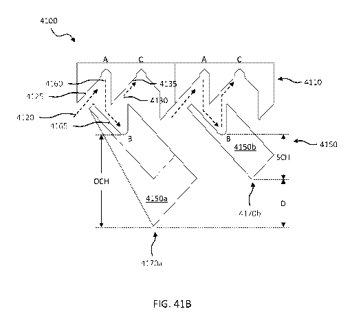
including any
electrical schematics any more detailed than found in FIG. 16.
[0093] FIG. 17 describes the software that might run on the Raspberry Pi
or other computer
on the drone during flight. The software might be written in Python 3 and
interface with the drone
through Mavlink. The Mavlink protocol is a low-level framework that provides
get and set access
to most of the drone's measurements, parameters, settings, and controls.
[0094] FIG. 18 shows how the latch attachment confirmation system is
wired to the
Raspberry Pi. Simple digital input to the Raspberry Pi might detect a voltage
across the 1 kOhm
resistor when the switch is closed, indicating the package has been lifted. No
voltage signal might
be detected when the switch is open, indicating the package has not yet been
lifted.
[0095] FIG. 19 shows the PCB design for confirming package attachment.
This component
acts as a simple connector circuit with a shield finger switch (BOM Item #36)
soldered onto the
rectangular patch. A cutout in the center of the PCB allows it to rest within
the bearing, and when
a package is lifted the bearing pushes down the switch, connecting the two
isolated wires.
[0096] A critical component in multicopter design is the flight control
board (FCB). The
FCB has an onboard accelerometer, gyroscope, and compass that together
estimate the position of
the drone using an Extended Kalman Filter. After passing this estimate and the
desired throttle,
roll, pitch, and yaw from the RC input through numerous control loops and
algorithms, the FCB
sends a pulse width modulated (PWM) signal to the electronic speed controllers
(ESCs) which in
turn control the speed of each motor.
[0097] The Pixhawk FCB was chosen, at least in part, because it is the
industry favorite.
Moreover, the Pixhawk 4 is faster and more updated than its ancestor, the
Pixhawk 2.1. The
Pixhawk 4 kit also included a PDB, and GPS module. Additionally, the Pixhawk 4
supports
Ardupilot, an open source flight automation firmware, and Mavlink, a common
protocol used to
communicate with external devices such as a Raspberry Pi companion computer.
[0098] Also critical to the design is the choice of the companion
computer. The companion
computer might run the algorithms within the Ardupilot software/firmware suite
and onboard Pixy
libraries that do the autonomous decision making. Like above, both our
research and Dr. Summers
pointed to the Raspberry Pi as the best candidate for our onboard computer. We
chose the
Raspberry Pi 4, 4GB RAM model to ensure that it is fast enough to run the
control algorithms
without slowing down/filling up RAM mid-flight. The Raspberry Pi has been
demonstrated to
-15-
CA 03167232 2022-07-07
WO 2021/154875 PCT/US2021/015318
interface well with the Pixhawk 4 and is listed as a recommended companion
computer on the
ArduPilot (Pixhawk firmware) website (ArduPilot Dev Team n.d.).
[0099] A camera may be needed to recognize the pickup site and determine
its location
relative to the current position of the drone in flight. We opted for the
Computer vision system
camera as it has onboard machine learning that easily allows
users/students/researchers to program
it to reliably recognize objects based on a single training instance of the
object. The on-board
algorithms heavily rely on contrasting color signatures so our design suggests
paining or otherwise
coloring the pickup site with a unique color in contrast with the surrounding
environment (which
will most likely be grass or concrete).
[00100] Lastly, the remaining components (frame, motors, ESCs) were
selected as
recommended by DJI in the Flamewheel kit. Additional considerations and
metrics used to finalize
selection of the frame, motors, propellers, and companion computers are
discussed below. We
chose a 6-armed multicopter (hex copter) as hex copters provide more thrust
than an equivalent
quad copter (allowing for heavier packages to be carried), are generally more
stable than quad
copters and are typically larger, allowing larger packages to fit under the
propellers without
interfering with thrust.
[00101] The fixed attachment was designed to fit underneath the drone and
hold a bearing
which attaches to the lifter. This design allows the bearing and lifter to
freely rotate, preventing
any torsional force on the drone and allowing the lifter and hook to mate, as
the hook is fixed
rotationally within a package.
[00102] A mechanism to verify that the package has mated with the latch
was developed to
improve system performance and reduce risk. This mechanism consists of a
spring powerful
enough to overcome the weight of the lifter, but not the weight of the
package.
[00103] Spring for fixed latch attachment justification equations are
shown below where F
is the force due to the weight of bearing and lifter, Ax is the distance the
latch travels to compress
spring and k is the spring constant. The desired range of spring constants was
calculated in order
to justify the selection of a particular spring and validate that it could
meet project requirements.
[00104] Equation 2:Hooke's Law: Force = Ax * k.
[00105] Applying
[00106] Equation 2 to the minimum value to activate the switch:
0.494 (N) = 6.7 (mm) * K (¨N)
M.171.
K = .494 = 0.074 (¨N ) ¨ Min K value to activate switch
6.7 M.171.
[0 0107 ] Applying
[00108] Equation 2 to the maximum value to activate the switch:
1.5(N) = 6.7(mm) * K (¨N) ¨ Max K value to still activate with small box
M.171.
1.5 n õ i. N ,
6.7
K = ¨ = U.GG .¨)
mm
[00109] Combining the minimum and maximum values to develop a range:
N N
0.074 (¨) <K <0.22 (¨) ¨ Range of usable spring constants
mm mm
[00110] When the package is attached the spring might be compressed and
the bearing
might make contact with a spring switch. This spring switch is in connection
with a printed circuit
board (PCB) that completes a circuit connected to the Raspberry Pi 4 B. The
dimensions of the
spring were constrained from the design of the latch attachment while the
spring constant was
-16-
CA 03167232 2022-07-07
WO 2021/154875 PCT/US2021/015318
calculated above. The full assembly is shown as a cross section view in FIG.
20, with the spring
being compressed by the bearing. Once this circuit is complete upon contact,
the Raspberry Pi 4
B might complete a circuit with the spring switch, confirming that the hook
and lifter have mated,
as shown in FIG. 19.
[ 00111 ] In order to attach the hook to the package and retain simplistic
manufacturing
techniques, the cardboard package design shown in FIG. 21 was created. This
design is unique in
that it uses the overlapping top face to keep the hook from sliding out of the
package and the first
top face to keep the hook from falling into the package. The overlapping top
flap (the left most
panel next to the flattened package cutout in FIG. 21) also ensures that less
tape needs to be used
to close a side edge of the package. The package height is restricted by the
height of the cones in
the pick-up system, the height of the legs, and the dimensions in the latch as
shown in FIG. 11.
According to calculations discussed above, the minimum package height is 52.42
mm. This
package design utilizes cut out flaps and insert slots on the top faces as an
additional reinforcement
mechanism for maintaining the package closure which is needed because the
entire weight of the
package is lifted from a singular point of the latch mechanism. Packing tape
is also used to both
secure this additional cardboard cut-out support and to close the sides of the
package.
[ 00112 ] Turning to FIG. 22, illustrated is one embodiment of a drone
assembly 2200
designed, manufactured, and operated according to one or more embodiments of
the disclosure.
The drone assembly 2200 in FIG. 22 includes, without limitation, the following
parts:
Cost
Part Cost/ QT
Name Full Name Description Vendor
Part Number
Number Unit Y Ship
ping
USAQ F550 Upper plate of
See
Upper 550mm Hexacopter Drone the drone hub" Frame
2202 $0 1
SD93904002
Plate Frame Integrated Power supports
Kit
Distribution Board (PDB) electronics
6 arms of the
USAQ F550
drone, See
550mm Hexacopter Drone
2204 Arm $0 6 connecting the Frame
SD93904003
Frame Integrated Power
upper and Kit
Distribution Board (PDB)
lower plates
USAQ F550 Upper plate of
See
Lower 550mm Hexacopter Drone the drone hub" Frame
2206
$0 1
SD93904001
Plate Frame Integrated Power supports
Kit
Distribution Board (PDB) electronics
Pack of 50, Amazon
only need , but
34. Connects addition
Arm to 91290A101_BLACK-OXIDE
al
2208 plate CLASS 12.9 SOCKET $0 1 arms to upper
5D93904004
and lower backup
screws HEAD SCREW
plates. Came is
with frame McMast
kit. er
¨17-
CA 03167232 2022-07-07
WO 2021/154875 PCT/US2021/015318
Readytosky 2212 920KV
Motors Brushless Motors CW CCW
2210 (Packs of for F330 X525 F450 S500
$32.00 6x2212 Amazon $64.0 2 SD93903010
920kV motors 0
4) F550 S550 DJI Phantom
Quadcopter(4PCS)
Genuine Gemfan 1038
(10x3.8) Propellers
by RAYCorp. 8 Pieces(4CW,
00
2212 Propellers 4CCW) Black - Carbon
$17. 1 10x3.8 (8pc5) Amazon $17.0 5D93904006,
0
SD93904007
Nylon 10-inch Quadcopters
and Mutlirotors Props
+ RAYCorp Battery Strap
Legs to assist
in pickup Sponsor
2214 Leg Legs (Manufactured Part) $0.28 3
system and Provide $0.83 5D93905001
Extensions
allow variable
package sizes
Amazon
Pack of 50,
, but
only need
Motor addition
91290A113 BLACK-OXIDE 8. Connects
Screws for al
2216 CLASS 12.9 SOCKET $0 1 motor to arms
5D93904008
"no- backup -
HEAD SCREW without legs
leg arms" is
below. Came
with frame kit
c M Mast
er
Amazon
Pack of 50,
, but
only need
addition
Screws for 91290A113_BLACK-OXIDE 8. Connects
al
2218 Leg CLASS 12.9 SOCKET $0 1 motor to arms
5D93904008
backup -
Extensions HEAD SCREW without legs
is
below. Came McMast
with frame kit
er
Onboard
3DR 100MW Radio
Telemetry Kit 915Mhz 915 component
$23.00 used to Amazon $23.0 5D93903005,
2220 Telemetry Kit Air and Ground Data 1
communicate 0 5D93903006
Transmit Module for APM2.6
APM2.8 PX4 Pixhawk with ground
station
Zeee 3S 11.1V 6000mAh 60C
RC LiPo Battery with (XT60
and Deans Connector) for RC
$39.00 3S 6000mAh Amazon $39.
2222 Battery Plane, DJI 1 0
5D93903001
battery 0
F450 Quadcopter,RC Airplan
e, RC Helicopter, RC
Car/Truck, RC Boat
Electronic
NIDICI BLHeli-32 30A ESC
Speed
32bit Brushless Electric
Controllers $42.00 Blheli 20A Amazon $84.0
2224 Speed 2-4s Controller for 2
5D93903002
(ESCs) ESCs 0
DShot1200 FPV Racing
(Packs of
Drone (Pack of 4)
4)
-18-
CA 03167232 2022-07-07
WO 2021/154875 PCT/US2021/015318
2226 Pixy Mount N/A N/A 1 N/A N/A N/A N/A
Lifter
2228 N/A N/A 1 N/A N/A N/A N/A
Assembly
Electronic
2230 N/A N/A 1 N/A N/A N/A N/A
Mounts
Cover for
2232 N/A N/A 1 N/A N/A N/A SD93905004
Electronics
GPS and GPS
PX4 Pixhawk 4 FMUv5
mount were
Autopilot with NEO-M8N Amazon $
2234 GPS $0.00 1 part of the
SD93903003
GNSS and PM07 Power -
FCB, so the
Management Board
cost is 0
Screws for
N/
2236 Lifter N/A N/A N/A N/A N/A
5D93904012
A
Assembly
Washers for
N/
2238 Lifter N/A N/A N/A N/A N/A
5D93904013
A
Assembly
[ 0 0 1 13 ] Turning to FIG. 23, illustrated is one embodiment of a lifter
assembly 2300
designed, manufactured, and operated according to one or more embodiments of
the disclosure.
The lifter assembly 2300 may be similar, in certain respects, to the lifer
assembly 2228 in FIG. 22.
The lifter assembly 2300 in FIG. 23 includes, without limitation, the
following parts:
Cost
Part Cost/ QT +
Name Full Name Description Vendor
Part Number
Number Unit Y Ship
ping
Fixed Latch Latch Attachment
2310 1
5D93901002
Attachment (Manufactured Part)
¨19-
CA 03167232 2022-07-07
WO 2021/154875 PCT/US2021/015318
Bearing to
Bearing Latch Bearing (Manufactured allow latch
2320 $0.13 1 $0.13
SD93901001
Assembly Part) lifter to
function
2330 Spring
5D93901009
Latch top
2340 5D93901006
piece
Latch
2350 bottom
5D93901005
piece
2360 Sensor PCB
5D93901012
Screws for
N/
2370 Lifter N/A
N/A A N/A N/A N/A 5D93904012
Assembly
Nut for
2380 Lifter N/A N/A N/ N/A
N/A N/A 5D93904013
Assembly A
[ 00114 ] Turning to FIG. 24, illustrated is one embodiment of a bearing
assembly 2400
designed, manufactured, and operated according to one or more embodiments of
the disclosure.
The bearing assembly 2400 may be similar, in certain respects, to the bearing
assembly 2320 in
FIG. 23.
[ 0 0 1 1 5 ] Turning to FIG. 25, illustrated is one embodiment of a fixed
latch attachment 2500
designed, manufactured, and operated according to one or more embodiments of
the disclosure.
The fixed latch attachment 2500 may be similar, in certain respects, to the
fixed latch attachment
2310 in FIG. 23.
[ 0 0 1 1 6] Turning to FIG. 26, illustrated is one embodiment of a package
and hook assembly
2600 designed, manufactured, and operated according to one or more embodiments
of the
disclosure. The package and hook assembly 2600 includes, without limitation, a
package 2610
having an opening therein, as well as a hook member 2620 operable to seat
within the opening in
the package 2610 and latch with a latch member of a lifter assembly, such as
the lifter assembly
2300 illustrated with respect to FIG. 23.
[ 0 0 1 1 7 ] Turning to FIG. 27, illustrated is an alternative embodiment
of one embodiment of
a package 2700 designed, manufactured, and operated according to one or more
embodiments of
the disclosure. The package 2700 may be similar, in certain respects, to the
package 2610 in FIG.
26.
[ 0 0 1 1 8 ] Turning to FIG. 28, illustrated is an alternative embodiment
of one embodiment of
a hook member 2800 designed, manufactured, and operated according to one or
more
embodiments of the disclosure. The hook member 2800 may be similar, in certain
respects, to the
hook member 2620 in FIG. 26. In the illustrated embodiment, the hook member
2600 is a female
hook member configured to engage with a male latch member.
[ 0 0 1 1 9] A major limitation of automated drone use is their limited
flight to charge time ratio
(about 1:3, at best 1:2). The batteries used in quadcopters, hexacopters, and
octocopters discharge
in use faster than they charge. Thus, a system reliant on automated drones
with internal batteries
would require multiple drones and charging stations for continuous work.
-20-
CA 03167232 2022-07-07
WO 2021/154875 PCT/US2021/015318
[00120] However, if drones were able to easily exchange external batteries
at a base station,
refueling time would be dramatically reduced. Batteries could be charged while
a drone is in flight,
using a different battery. A single drone could provide nearly continuous up-
time, and two drones
could overlap to provide truly continuous up-time. Truly continuous operation
is desirable for
many applications, including surveillance.
[00121] Battery exchange could also allow propeller drones to carry
payloads across larger
distances. They would not be limited by a single charge in their maximum
delivery distance. They
could stop at a base-station, exchange a battery, and continue to complete the
payload delivery or
to another base station. They would complete such a route much faster than if
they needed to fully
recharge at each station.
[00122] A rotating tension latch mechanism integrated into an external
battery allows for
fast exchange of batteries without the need for additional actuators. This is
beneficial from the
perspective of the drone because it limits power consumption and weight. This
is beneficial from
the perspective of the base station because it is economical. The rotating
tension latch does not
require rotational accuracy, which allows for flexibility in the designs of
both the base stations and
the drones.
[00123] Other latching mechanisms are feasible for battery exchange if the
drone can
accurately align with the base station.
[00124] Battery exchange will allow for two new methods of delivering
payloads or
packages. First, with multiple base stations along a route, a drone could
deliver packages across
longer distances without needing to stop to charge. The drone would simply
need to reach a base
station with a charged battery, change batteries, and continue along its
delivery route. It could stop
at multiple base stations.
[00125] Second, battery exchange would allow Base Delivery Trucks to use
one or more
drones to finish delivery of packages or payloads. The drones would be able to
deliver packages
nearly continuously because they would be able to exchange batteries and
continue flying, rather
than docking and recharging.
[00126] Automated drones could be used for security or surveillance more
efficiently
because they would have very little downtime. Drones could provide a high-
altitude perspective
of an area until the battery is near depletion, then exchange batteries and
return to the skies. Two
drones could reach 100% uptime so long as one drone is always in the air while
the other is
exchanging batteries.
[00127] Battery exchange is even more valuable in scenarios that require
multiple drones
for surveillance. If, for example, two separate regions, Region 1 and Region
2, needed surveillance,
three drones (Drone A, Drone B, and Drone C) would provide 100% uptime by
cycling. Drone A
could start in Region 1, and Drone B would start in Region 2. Drone C would,
after some time,
replace Drone A in Region 1, allowing Drone A to exchange its battery. It
would then replace
Drone B in Region 2, allowing Drone B to exchange its battery before relieving
Drone C, and so
on. So long as the travel and battery exchange time allow, the only one
additional drone would be
needed to surveil any number of regions.
[00128] Many automated tasks will become more economically viable with the
use of
battery exchange on a drone. The best ratios of flight to charge ratio are
1:2¨a 60-minute charge
could give 30 minutes of flight. Assuming the typical Drone Return Mode time
is 3 minutes (total,
in both directions), a full Work Cycle for a Conventional Drone would look
like this:
Drone Active Mode ¨ 27 minutes
Drone Return Mode ¨ 1.5 minutes
-21-
CA 03167232 2022-07-07
WO 2021/154875
PCT/US2021/015318
Drone Charge Mode ¨60 minutes
Drone Return Mode ¨ 1.5 minutes
Such a drone would have 30% Uptime.
[00129] A full Work Cycle for Swappable Battery Drone would look like
this:
Drone Active Mode ¨ 27 minutes
Drone Return Mode ¨ 1.5 minutes
Drone Swap Mode ¨ 0 minutes (incl. in the Return Drone Mode)
Drone Return Mode ¨ 1.5 minutes
Such a drone would have 90% Uptime.
[00130] In this scenario, a Swappable Battery Drone would be able to do 3
times more work
than a Conventional Drone provided the Swap Station has enough batteries. So,
the Drone
Efficiency Improvement in this scenario is 2.
[00131] A simple equation that can be used for determining the Uptime of a
Conventional
Drone is:
Active Time Active Time
UPtimeConventional = __________ = ______________________________________
Cycle Time Active Time + Return Time + Charge Time
[00132] A simple equation that can be used for determining the Uptime of a
Swappable
Battery Drone is:
Active Time Active Time
Uptimeswappable = ___________________
Cycle Time = Active Time + Return Time
[00133] The Drone Efficiency Improvement for similarly configured
Conventional vs
Swappable Drones can be calculated by:
UP tim eSwappable
Drone Efficiency Improvement = ri : 1
uptor eConventional
Active Time + Return Time + Charge Time
= 1
Active Time + Return Time
[00134] Because Charge Time is greater than Active Time + Return Time, a
Swappable
Battery Drone will always be able to perform the same amount of work as at
least two, if not more
Conventional Drones. Since drones that do automated tasks are typically quite
expensive, using
Swappable Battery Drones is more economical than automatically charged
Conventional Drones,
so long as the battery swapping mechanisms are not more expensive than an
entire drone. The
mechanisms should not add much to the cost of a drone because they do not
require moving parts.
[00135] It should also be noted that a Charge Station capable of charging
multiple
Conventional Drones to match the total Uptime of a Swap Station would require
nearly all the
same electronic components and mechanical components. It would have to be
larger, however,
because it would need to accommodate multiple landed drones.
[00136] A Swappable Drone would, therefore, require additional mechanisms
and batteries
that would be insignificant against the cost of an industrial drone.
[00137] The batteries could be encased in a cylindrical housing with
contours on the
cylindrical exterior to form the Latch portion of the Rotating Tension Latch.
If a battery as a Male
Latch was used, the drone would simply need a hole with 3 pins to act as a
Female Hook to pick
up and release the batteries.
-22-
CA 03167232 2022-07-07
WO 2021/154875 PCT/US2021/015318
[00138] This is particularly advantageous if the drone is using as
Rotating Tension Latch
for moving payloads ("Functional Latch"). The portion of the drone that
receives the batteries can
be vertically higher than the "Functional Latch" used for move payloads. The
batteries can be
positioned higher up on the Swap Station so that the "Functional Latch" does
not crash into the
Swap Station during Drone Swap Mode. Alternatively, the Battery could be the
male Hook of the
Rotating Tension Latch.
[00139] While it is not absolutely required, the use of a Rotating Tension
Latch for the
swappable batteries would benefit from the use of springs to assist gravity
for the axial force. This
would keep the batteries stable in flight and ensure good electrical contact
against the batter leads.
[00140] The springs can be located on the drone or on the battery. The
springs could be part
of the contact pins that make the electrical connections between the battery
and the drone.
[00141] The leads for the battery contacts could go through the cam pins
of the latch. The
Lower Vertical Limit of the cam surface of the latch would need to be a mating
contact point for
each pin. Because the battery can be inserted at any rotation, this means the
leads need to be
adjusted with electronic switch system or somehow otherwise compensate for the
change in
orientation of the leads. A marker can be placed on the top of the battery
that helps the system
identify orientation.
[00142] The top and/or bottom of the battery could have the contact
points. They could have
protruding pins, but it is more beneficial to have simple surface contacts on
the battery and pins
(spring or otherwise) on the drone.
[00143] While any geometry of contacts could work, ideally the contacts on
the battery
would be concentric rings (one contact in the middle could be a filled
circle). If 3 leads are desired,
the battery would have 3 concentric rings (one could be filled in the center).
The mating portion
would have 3 pins configured to mate with each ring, regardless of the angular
orientation of the
battery. This configuration does not require the drone to identify which lead
is which and adjust,
because it will always be the same.
[00144] This configuration can be replicated on the bottom of the battery
so that the Charge
Station can charge the battery in the same way.
[00145] Both methods listed above could be used: a contact on the top and
bottom could be
used along with the contacts on the pins. The contact on the top could be
positive, the one on the
pins could be negative (or vice versa), so a correct orientation would not be
required.
[00146] Wireless power transfer (WPT) methods have several advantages over
electrical
contact for power transfer. The primary advantage for this application is that
they can be made
weather-proof so that exposure to rain does not short leads on the battery,
drone, or swap station.
WPT methods are also more reliable in a couple of ways: contact cannot be
"missed" so alignment
of the electrical leads does not need to be as precise, contact will not fail
from fatigue or repetitive
use or from debris or corrosion. WPT methods for this application include
Inductive coupling
(including resonant inductive coupling), capacitive coupling, or even far-
field methods like
microwave or laser transmission. Currently, inductive coupling is the most
likely method to be
used for this application. The term inductive coupling will be used with the
understanding that it
includes resonant inductive coupling.
[00147] Inductive coupling can be achieved using traditional coils by
putting a transmitting
coil on the top of the battery and the receiving coil configured to be right
above transmitting coil.
The receiving coil could be integrated into the spring system that retains the
battery in the Lower
Vertical Limit when using the rotating tension latch configuration for closest
possible positioning.
-23-
CA 03167232 2022-07-07
WO 2021/154875 PCT/US2021/015318
[00148] A possible advantage for this system would be using concentric
coils because the
battery will at least partially be inserted into the drone's receptacle.
Rather two coils with similar
shape and circumferences, the battery could have a coil positioned anywhere,
such that there is a
larger coil within the drone that would surround the battery and be positioned
so it is spaced
vertically optimally when the battery is at the Lower Vertical Limit when
using a rotating tension
latch battery. This method could also provide positional feedback of the pins
with respect to the
vertical limits. As the coils change vertical spacing, the magnetic fields
will change. These changes
can be evaluated based on the configuration to determine the approximate,
vertical relative position
of the latch and hook. If this is not sensitive enough to determine actual
position, change in relative
position could be used. When the drone senses that the magnetic field is not
changing as it lowers
or raises, it can be assumed that the latch system has reached a Vertical
Limit. Multiple coil pairs
could be used in this configuration to potentially optimize power
transmission.
[00149] As of this date, WPT is not as efficient as tradition electrical
contact power transfer.
Current techniques are roughly ¨85% efficient, though efficiency can increase
as the technology
is optimized. Because efficiency is important to drone performance, this
system may only be viable
in conditions where reliability and weather considerations are of primary
importance over flight
time and/or efficiency. Defense systems could a viable application.
[00150] While the main battery power for most of the function of the
drones will come from
Swappable Batteries, a small internal battery may be used for a few functions.
[00151] An internal battery could keep some functions running if the
external batteries
malfunction or come lose. If a drone does an Emergency Landing, it could send
coordinates of its
location. Its cameras could remain active, etc.
[00152] Depending on the Battery Swap Method used, an internal battery
could allow the
drone to complete a Battery Swap without having any (or less than maximum)
external batteries
in place. It could release all (or some) of its batteries, then use the
internal battery to move a short
distance to pick up and engage the new batteries.
[00153] Once the new batteries are engaged, they can recharge the internal
battery while in
flight.
[00154] Remote Swap Stations can be deployed with renewable charging
methods so that
they can operate off the grid. They could also have larger batteries. They can
be used stand-alone
or in conjunction with other power sources. Potentially, the Swap Stations
could be powered by a
generator. Drones could even refuel the generators. Swap Stations could also
be connected to the
"grid".
[00155] Drones are typically designed to be balanced such that the COM is
centered with
respect to the propellers. Because the battery or batteries account for a
significant portion of the
drone's weight, the effect of the battery or batteries on the COM of a drone
should be considered.
[00156] Exchange methods where the drone drops a battery and moves to pick
up a new
battery will require Imbalanced Flight unless the battery is in the center of
the drone. Centering
the battery on the drone is not always ideal, so if the drone is not capable
of Imbalanced Flight, a
different solution is needed.
[00157] Two batteries can be used, positioned on opposite sides and
equidistant from the
COM (two differently sized batteries can be used, and their position would be
on opposite sides of
the COM, but at distances proportional to respective masses to balance the
drone.) When both
batteries are engaged or released, the COM should be consistent.
[00158] Four battery receptacles could be used to limit how much flight
(if any) is required
to be powered by the internal battery. They would be configured in pairs, each
pair configured as
-24-
CA 03167232 2022-07-07
WO 2021/154875 PCT/US2021/015318
described above. When the drone reaches a charge station it will land so that
it engages two new
batteries in the empty receptacles, and releases its spent batteries into the
charging docks of the
Swap Station at the same time. Any number of pairs could be used. They would
not need to be
equally angularly spaced. Unequal spacing allows for the drone to land at
different angles to
perform a different function (like pick up a payload).
[00159] A Swap Station can include robotics to move batteries from the
swapping area to a
charging area. This is beneficial for a Swap Station that is servicing many
drones and/or where
space is limited. For example, if a Base Delivery Vehicle is using drones to
finish delivery of
payloads, it may be beneficial to have a single landing location for all
drones. The drones would
exchange batteries, then the spent batteries would be transferred robotically
to be charged, and
recharged batteries would be placed in the landing location for the next drone
to pick up. This is a
Mass Swap Station.
[00160] A Small Swap Station is a station without robotics. The drones
will exchange
batteries, and the batteries will charge in the location they are dropped off.
[00161] The rotating tension latch design for the battery exchange has
been described above.
The benefits of this are that no additional springs are required (gravity is
the driving force for the
latch), and it does not require as much precision (especially in terms of
rotation). It also fits well
around a cylindrical battery pack.
[00162] A spring actuated cam system can be used to latch the battery to
the drone and drop
it off, similarly to the rotating tension latch. This would require more
precise rotational orientation
than a rotating tension latch. This could be configured around a rectangular
(prismatic) battery
pack, or a cylindrical battery pack.
[00163] The batteries could be actively latched with actuators on the
drone or in the Swap
Station using any number of latching mechanisms.
[00164] Rain could be problematic for external batteries. If the leads get
wet, they could
short the circuitry. One option is to use wireless charging and/or induction
power transfer on the
batteries so there are no exposed contacts. Another is to ensure the batteries
are not exposed to the
elements when they are in the drone. Flaps or covers for the batteries can
engage when the drone
is in flight, and disengage when it lands. This can be done actively or with
mechanisms that are
activated during landing by the weight of the drone. Swap Stations could be
covered, drones could
enter a drying area where they would remain in place while they dry the
bottoms so that water does
not drip on the exposed batteries or leads of the swap station. The drying
could be done by a
separate fan, or even by the airflow from the drone's own propellers.
[00165] The openings for the battery receptacles on the drones could be
gasketed. This
would be particularly viable with a cylindrical battery pack using a rotating
tension latch or similar
type of engagement mechanism and battery leads on the top of the battery. The
gasket could be
slightly conical, pointing downwards from the drone. As the battery engages,
it would curl the
gasket upwards, and then as the battery goes downwards toward the Lower
Vertical Limit, it will
pull the gasket back down, forming a seal. This would protect the leads from
water.
[00166] Additional pick-up methods could be used. For example, a slide,
glide, and latch
method could be used. Rather than simply lowering directly onto a payload to
engage the latch, a
"Swooping" motion could be used to align the payload with the latch. The drone
would be
equipped with at least one extension (though probably at least 2) that would
hang or be fixed to
the bottom of the drone. It could be a leg or pole that could also serve as
landing gear. The drone
would move down and towards the package such that the extension would contact
one side of the
package. It would then slide the package as it moves parallel to the ground,
thus aligning the
-25-
CA 03167232 2022-07-07
WO 2021/154875 PCT/US2021/015318
package with respect to the drone and its extensions. For example, it could
have two extensions
that contact to adjacent sides of the package, thus trapping it on a corner.
As the drone would move
parallel to the ground surface, towards the center of the package, thus
aligning the package
consistently with the drone. Then the drone would lower to engage the latch
and hook, which
would be configured to be aligned by this motion. The drone would then raise
when the latch
system reaches the First Vertical Upper Limit, and lift the payload.
[00167] A benefit of this system is that it reduces the accuracy
requirements of the drone
positioning with respect to the latch and hook without the need for a special
landing dock. One
requirement is that the package be able to slide along its resting surface and
that there be adequate
room for the drone to slide the package before lifting. The extenders would
also have a secondary
benefit of limiting the rotation of the package in flight.
[00168] A disadvantage of this system is that the drone would be
configured to lift a specific
configuration of payloads where the hook or latch that is on the payload is a
specific distance from
a corner or whatever feature is being located by the extensions. This can be
remedied slightly by
having several extenders of different lengths at different distances from the
latch so that the drone
can pick up several configurations of packages.
[00169] For example, one drone could have two sets of extenders: one set
configured to
engage a payload that is 300mm x 300mm x 300mm and another to for a payload
that is 600mm x
600mm x 600mm. The extenders or the latch could be on spring loaded mounts
that allow them to
retract upwards towards the drone. The springs would be just strong enough to
ensure that the
extenders or latch system are fully extended when they are not being acted on
by any other force
(so just enough to overcome friction). This way, if the drone is picking up
the larger payload, the
extenders configured to engage the small package would be pushed upwards by
the payload. They
could have wheels or low friction nubs so that they would slide along to the
top surface of the
payload. This allows the extenders for the larger payload to engage the
payload. Alternatively, if
the drone is picking up the smaller package, the extenders configured to
engage the larger payload
might be retracted as they contact the ground surface, allowing the drone to
lower to the necessary
position.
[00170] It may be beneficial to have retracting extenders even if they are
configured for one
payload size. This would allow the extenders to reach further down along the
side of the package,
avoiding tipping. Since they are able to retract, they can reach further down
so that the extenders
do not block the drone from lowering further down to engage the latch once it
is aligned.
[00171] For cardboard pick-up methods, the cardboard may contain the hook
or the latch.
For example, the hook can be formed from cardboard. It might be preferable to
have an even
number of "pins" because they would be folded, thin cardboard, and maintaining
another angle
would require additional bends. This method would not work well with heavier
payloads because
cardboard would not support much weight. This method is ideal for very light
packages. It would
function similarly to a standard latch, in that it can pick up at any
rotational orientation.
[00172] Alternatively, a female latch may be integrated into a cardboard
package can be
formed by perforating and cutting patterns into the package. These patterns
could be added
direction to a standard package, or raised so that when the hook inserts, it
does not interfere with
the contents of the package.
[00173] Such a configuration reduces package cost by not requiring
additional parts (a
plastic hook), and minimizing assembly efforts. The drawback to this method is
that the drone
needs to be relatively aligned with the latch for pickup. This can be
accomplished with precise
drone control or landing features that help align the drone on pickup. The
hook would be attached
-26-
CA 03167232 2022-07-07
WO 2021/154875 PCT/US2021/015318
to the drone in such a way that when it is not holding a package it will
return to the same rotational
orientation with respect to the drone. One option is to put the hook on a
rotational bearing that is
spiraled so that gravity will rotate the hook to the known orientation.
Another option is to use a
spring that returns the hook to the same known orientation.
[ 0 01 7 4 ] The cam surfaces would be cut into the cardboard. The cam
surface would need to
be cut into the cardboard, and then folded. It could be folded during package
assembly, or the force
of the hook coming down on the package could fold the contours far enough to
engage the hook.
[ 0 01 7 5 ] Because drones are technically capable for rotating precisely,
some latches can be
designed that do not automatically release using the contours. A drone could
lower into position,
rotate, and raise up to engage and pick up a package. Then it could lower
until the package touches
the ground, continue lowering and rotate back the other direction to disengage
a latch.
[ 0 01 7 6] This method simplifies the latch, but complicates the drone
movement. It also
requires higher degrees of control and time to release packages. It also
requires precise pickup
orientation with respect to a package without the assistance of a landing
assistance jig that would
hinder rotation.
[ 0 01 7 7 ] A different kind of latch using cardboard could be configured
to use the cardboard
to hook into a fixed hook on the drone. The drone would lower onto the
package, and then raise
up. As it lowers, flaps in the cardboard would be bent down and over a ridge
on the hook attached
to the drone. When the drone raises up, that flap would be configured to hook
onto the ridge, so
that the package is lifted. When the package is lowered again, it could be
lowered further down
and the drone would be configured to break the flaps or rotate to release the
package. The different
heights for pickup and drop off can be set by a landing jig that stops the
drone from lowering too
far, or it can be precisely controlled by the drone.
[ 0 01 7 8 ] Release could be accomplished by pulling the hook up, breaking
or disengaging the
flaps. The hook could be pulled up by an actuator on the drone
(disadvantageous because it adds
an actuator and thus weight). Or it could be configured so that as the drone
continues lowing, the
bottom of the hook hits a stop in the package, pushing the hook up. The hook
would be configured
to move linearly up towards the drone. As the hook moves up, the top of the
package hits a feature
on the drone, stopping the package from moving relative to the drone. As the
drone continues to
lower, the hook will push up and out of the latch, breaking or otherwise
disengaging from the
cardboard flaps.
[ 0 01 7 9] Turning to FIG. 29, illustrated is one embodiment of a Package
Attachment 2900
designed, manufactured and operated according to one or more embodiments of
the disclosure.
The hook 2910 snaps into the cut out in the package 2920 and is rotated
(counter-clockwise in
image above). The snaps 2930 extended outwards, locking rotation. The radial
extensions 2940 of
the hook hold the hook to the cardboard axially and angularly. They could
squeeze the package
slightly on rotation. Package shown here is simplified as a cylinder to show
the cut out. FIGs. 30
and 31 illustrate the hook 2910 and the package 2920 separate from one
another.
[ 0 01 8 0 ] Turning to FIGs. 32-36 illustrated is a slide and tape method
3200 for coupling a
hook member 3210 to a package 3220. This method shows the top of a package
3220 that traps
the hook member 3210 using the cut outs shown so that when tape 3230 is
applied along the seam
3225 of the package 3220, it retains the hook member 3210. This tape 3230
could be the same tape
closing the package 3220.
[ 0 01 8 1 ] Turning to FIG. 37, illustrated is an alternative embodiment
of a rotating latch
member 3700 designed, manufactured and operated according to one or more
embodiments of the
disclosure. A key concern with drone delivery is safety, specifically with
carrying packages over
-27-
CA 03167232 2022-07-07
WO 2021/154875 PCT/US2021/015318
public areas. A reliable system of holding the package is required. The
standard latch contours
with one bottom vertical limit is reliable. The package can only be dislodged
if it moves upwards
relative to drone. A spring system can be used to push down on the package
during flight so that
an upward force on the package must abruptly overcome the weight of the
package and the force
of the spring to dislodge the package.
[ 00182 ] However, in order to further improve the reliability of the
latch, multiple locking
contours can be added. Thus, FIG. 37 illustrates the standard configuration
with an additional
lower vertical limit. This, ultimately leads to an additional upper vertical
limit in certain
applications. The contour 3700 of FIG. 37 includes an upper portion 3710 and a
lower portion
3750. While not illustrated, the lower portion 3750 may include a first lower
portion 3750a and a
second lower portion 3750b. In the illustrated embodiment, the upper portion
3710 and the lower
portion 3750 cooperate to form at least first and second channels. In the
illustrated embodiment,
only the first channel is shown. Each of the first and second channels include
in order a first
upwardly sloping path 3720 defined by a respective first upwardly slanting
guide surface 3725
(and optional first upper limit surface [A]) of the upper portion 3710, a
first downwardly sloping
path 3760 defined by a respective first downwardly slanting guide surface 3765
and a first lower
limit surface [B] of a respective lower portion 3750a, a second upwardly
sloping path 3730 defined
by a respective second upwardly slanting guide surface 3735 (and optional
first upper limit surface
[C1) of the upper portion 3710, a second downwardly sloping path 3770 defined
by a respective
second downwardly slanting guide surface 3775 and a second lower limit surface
[a] of the
respective lower portion 3750a, a third upwardly sloping path 3740 defined by
a respective third
upwardly slanting guide surface 3745 (and optional first upper limit surface
[E]) of the upper
portion 3710.
[00183] The motion of the pin would be to first fall to the first upper
vertical limit [A] (e.g.,
if it existed), as the hook engages the latch. Then, as the drone lifts up,
the pins would reach the
first lower vertical limit [B] and lift the package. This is the same as the
standard configuration.
However, with a second locking contour in place, when the hook is pushed
upwards with respect
to the latch (either by landing or through some error or turbulence, the pin
would go towards the
second upper vertical limit [C] (e.g., if it existed), and then down to the
second lower vertical limit
[D]. It is also possible that in such an error or turbulence, the pin could
fall back to the first lower
vertical limit [B], in which case the package is still retained safely.
Finally, in the case of the double
lock, the pin would move towards the third upper vertical limit [E] and then
release.
[ 00184 ] In certain embodiments, no physical upper limits exist, as shown
by the dotted lines
3790 in FIG. 37. In said embodiment, the theoretical upper limits are thus set
by how far the
rotating latch member is allowed to drop in each one of the channels. For
instance, in the
embodiment of FIG. 37, if the pins were in the first theoretical Upper
Vertical Limit [A], the
rotating latch member 3700 would be allowed to drop further than if the pins
were in the second
theoretical Upper Vertical Limit [C] or third theoretical Upper Vertical Limit
[E]. In the illustrated
embodiment having no physical upper limit, the upper portion 3710 includes at
least a first upper
portion 3710a, second upper portion 3710b, and a third upper portion 3710c.
[ 00185 ] Advantages: The level of reliability against an accidental
disengagement is squared
using a double lock (additional locks continue to increase the reliability
exponentially).
[ 00186 ] Disadvantages: The package must be "dropped" twice in order to
disengage
normally. Additionally, the diameter of the latch and hook will increase in
order to add the
additional locking contours without changing pin size or performance.
-28-
CA 03167232 2022-07-07
WO 2021/154875 PCT/US2021/015318
[00187] In certain embodiments, the rotating tension latch employs a
tether designed. The
tethered design, in one embodiment, employs a collapsing cone, as discussed
below. The tethered
design, in one or more other embodiments, may employ a catch for the tether.
In certain
embodiments, the process of picking up a package with the tether may be
conducted without a
sensor. Using a rotating tension latch on a tether may allow for a drone to
use it to pick up and
drop off a package without a sensor to detect the pins' relative locations to
the upper and vertical
limits.
[00188] If the approximate distance from the drone to the hook is known or
can be
estimated, the tethered latch can be lowered further than required and given
slack. So long as the
latch is lowered far enough to engage or disengage the latch, it can be
reasonably assumed that the
package was released. A camera can be used to confirm attachment or detachment
of the package.
[00189] For the engagement, the maximum vertical distance from the first
Upper Vertical
Limit of the latch to the pins should be calculated ("MVD"). If this is an
estimation or if there is
some amount of error, this distance value should include the error. So if the
nominal distance is
estimated to be 20m, but there is a possibility of +/- 20cm of error, the MVD
as described would
be 20.2m.
[00190] The drone would either lower itself or lower the tether via a
winch or other method
by the calculated MVD, and then lift tether. The drone can either self-align
to the latch, or it can
use an alignment jig. As the drone lifts the tether (again, either by flying
higher or by using a
winch) first, any slack in the tether will be lifted, and then the package
will be lifted while engaging
the latch. A camera can be used to confirm attachment of the package.
[00191] In the example above, there could be as much as 40cm of slack in
the given in the
tether.
[00192] For the disengagement, the MVD is calculated as the maximum
vertical distance
from the second Upper Vertical Limit plus the height of the pins of the hook
relative to the bottom
of the package. Again, the maximum amount of error must be added to ensure
disengagement.
[00193] The drone would lower by this MVD as described in the Engagement
method. It
would then lift the tether, and after the slack has been taken up, it will
release the package. A
camera can be used to confirm detachment of the package.
[00194] The above method has the advantage that is does not require a
sensor to detect state
of the latch. However, it may be a less reliable engagement and disengagement
method.
Additionally, it requires the ability to detect and confirm the engagement and
disengagement
visually and accurately. Moreover, once the package is retracted, the drone
cannot confirm it is
still holding the package. An accidental drop would go unnoticed. Furthermore,
allowing slack in
the tether could tangle with some component and lead to a failure, and this
method is likely slower
than using a sensor to detect engagement. For example, the tether must be
lifted slowly until it is
known that line is taught to prevent jerking. A sensor would allow for minimal
slack and speed up
the pickup and drop off process.
[00195] In certain embodiments, a split cone design may be used assist in
connecting/disconnecting a drone or other device to the package. In at least
one embodiment, a
catching structure is used. The catching structure can be formed out of a
metal rod (like a coat
hanger) to achieve the desired shape. It can be made in many ways, so long as
the receiving angle
allows the tether to constantly slide to be located above the alignment cone.
FIG. 38 illustrates
one embodiment of this receiving angle.
[00196] The drone, crane, or robot will tether towards the concave of the
alignment structure
and will then move away in the same direction when it has engaged the package.
The slotted cone
-29-
CA 03167232 2022-07-07
WO 2021/154875 PCT/US2021/015318
design (e.g., where the cone does not come apart, but rather has an opening
for the tether to pass
through on exit) can be used with the alignment structure as well. This method
uses a simpler pick-
up station, but requires the drone to lift the package in such a way that it
does not crash into the
cone.
[00197] Delivery companies are struggling to find good methods of landing
a package in a
specific, safe place, due to wind, etc. Using a base station designed for pick-
up or drop-off instead
could allow for precise drop-off. For home delivery, recipients would have a
simple base station
(for example, the station with 3 cones to receive the drone legs, or 3
extensions to receive the drone
cone. The deliverer can supply guidelines for location of the base station,
such as clear view of the
sky, clear of trees, cables, and other obstacles, and/or safely away from pets
or wildlife. The base
station could have visual features for a drone to detect, or some sort of
electronic beacon for
guidance. A human could help locate the base station remotely on the first or
all deliveries.
Packages would then be delivered to the exact location the recipient desires,
and features in the
base station can be included to protect the package until the recipient as
retrieved it.
[00198] For more advanced home delivery, a base station could be built
into a roof or a wall
of a house. The base station could open as the drone approaches, so it is
otherwise protected from
the elements. Once the drone as successful dropped the package of, the base
station can close, and
also bring the package into the house. It could elevator down, the bottom
could pull down and the
package could move along a slide. This could be actively or passively
automated or done manually
by a recipient.
[00199] Delivery companies may prefer to deliver to a locker or a separate
station where
customers can pick up their packages, or where an automated cart can
completely delivery. A base
station like this would receive the package and place with enough precision to
be acted on
automatically by another robot. The base station could scan a barcode, image,
or electronic
signature on the package to identify it and/or its next or final destination,
but a computer system
could track deliveries across drones and know or expect what package has been
placed. Scanning
could be done to confirm the correct package is in place.
[00200] In one example, the base station could be configured so that the
packages is placed
directly on a conveyor, which then moves the package away from the base
station. It could be
dropped into a bin, possibly for later sorting, or it could then be acted on
by another robot.
Similarly, the base station landing area could have low enough friction with
the package the base
station could automatically slide the package from the landing position onto a
slope where it could
slide, or simply onto a flat surface that is clear of the landing station.
[00201] In another example, the hook on the package used by the rotating
tension latch on
the drone could be used again by a robotic arm to initially move the package,
or it could be used
after the conveyor or slide described above. This arm could place the package
into a locker, onto
an automated cart, into a bin, or it could be built into an automated cart to
transport further.
[00202] The rotating tension latch allows for simple, automated pickup and
drop off, which
allows for additional uses for delivery drones. In one example, provided is a
point-to-point
delivery method. For extremely fast deliveries from sender to receiver, a
drone could pick up the
package directly from the sender and transport it to the receiver directly.
The sender would likely
need a base station for pick up, though an advanced drone with good control
could conceivably
pick up a package without assistance. The sender would likely need a package
or container
configured with a hook to engage the latch. Container could be reusable, it
could be rigid plastic
with a built in or attached hook. It could also be a pre-fabricated cardboard
package, either fully
assembled, partially assembled, or simply an unfolded cardboard package with
separate hooks and
-30-
CA 03167232 2022-07-07
WO 2021/154875 PCT/US2021/015318
instructions for assembly and packaging. It may be advantageous to use
specific colors on the
packages for contrast. The sender may need to provide information about the
package, like weight,
size, etc. The base station or the drone could measure the mass before pick-up
or after latch
engagement.
[00203] When the drone reaches the base station for pick-up, it can use a
camera to ensure
a package is correctly in place before attempting pickup. The base station
would likely need
physical guides to ensure the package is placed in the correct location with
enough precision for
the latch to engage. This method could be used to return items that were
delivered (if they were
damaged or otherwise unwanted). This could also be used by a delivery company
to pick up
packages from the sender and bring them to their facility for further
delivery.
[00204] In at least one embodiment, the method taught herein provides a
delivery
confirmation. For example, on-board cameras could be used to take pictures of
the delivered
package for confirmation and to notify the receiver.
[00205] A method according to the present disclosure could also be used
for Mobile Ground
Control and/or Assistive Device for Remote Payload Pickup in Unknown Terrain.
The purpose of
this design is to ease the process of remote collection of payloads when these
payloads must be
collected in, among other conditions in which the user lacks information about
the conditions at
the pickup location, new/unknown terrain, orientations, unknown weather
conditions, are of
unknown weight or unknown shape etc. Potential applications include the return
of packages from
homes, collection of lost materials in remote areas, collection of payloads in
conditions dangerous
to humans and more. The exact location of the payload is not always necessary
in order to collect
the payload. The scouts and collectors can potentially be vastly different
devices with different
strengths, weaknesses and associated costs and thus will be able to minimize
the weaknesses of
each other.
[00206] The design involves three major systems interacting together in
these unknown
conditions. First, the payload to be collected, second the "scout" or
"scouts", a drone(s) or other
device(s) that travel(s) to the pickup location prior to the arrival of the
third system the "collector"
or "collectors", which is/are the device(s) that will ultimately collect the
payload. Scouts and
collectors could both be equipped with sensors and control systems that allow
them to navigate to
the location of the payload. Scouts may also have components that allow them
to reposition the
payload prior to the arrival of the collector, which could use information
from the scout, including
live feedback from sensors on the scout, which can serve as a ground control
station, to collect the
payload.
[00207] The process of this system's functioning is outlined briefly
below. This process can
be conducted autonomously, with manual assistance/control or a combination of
such. Payload
collection request submitted with location information. Scouts and Collectors
travel/are
transported to payload. These may be scrambled from different positions,
controlled
autonomously or manually and a combination of such. The number and type of
scouts and
collectors could depend on the area being surveyed, the payload to be
collected and other
information. The scouts and collectors may transport themselves the entire
distance or they may
be transported by another subsystem, such as a helicopter, truck etc. or may
arrive at the site via a
combination of such.
[00208] In one embodiment, the scouts arrive at payload. The scout(s) will
first search for
and identify the payload, if the location is unknown. Scouts can send
information on site to
collectors. The collectors could follow the optimum path to the pickup site
based on information
sent by the scouts. Then, the Scouts can prepare pickup site for collectors.
Prior to the arrive of
-31-
CA 03167232 2022-07-07
WO 2021/154875 PCT/US2021/015318
the collectors the scouts may make adjustments to the site and payload to make
collection easier,
such as clearing debris, repositioning the payload, affixing new means of
collecting the payload to
the payload and more. This will not always be necessary. Thereafter, the
collectors arrive at
payload. The collectors will use information relayed by the scouts to travel
to the location of the
payload as efficiently as possible. The scouts may then assist with collector
collection of payload.
Scouts may remain at the site after the arrival of the collector to relay live
information such as
relative position of the payload and collector to the collector in order to
assist with the pickup
process. They may also remain to actively assist with the pickup via use of
onboard actuators or
other components. With this accomplished, the collector may collect the
payload. With the
assistance of the scouts and any onboard sensors the collector successfully
collects the payload.
Finally, the Collectors and Scouts may return with payload. For example, after
securing the
payload the collectors and scouts travel to their planned final destinations.
[00209] In at least one embodiment, the scouts may continue to provide
information such
as wind speed, objects in the way of the collector, other moving objects,
weather information and
more, for concurrent or later use.
[00210] Turning to FIGs. 39 and 40, illustrated is one embodiment of a
split cone design
3900 designed, manufactured and operated according to one or more embodiments
of the
disclosure. The split cone design, in at least one embodiment, is composed of
a catching structure
(shown here built out of PVC pipe and fittings) to catch a tether with the
hook attached to it, two
halves of a split alignment cone on hinges, and a baseboard that everything
sits on. The catching
structure is used as a barrier to catch and align the tether so that the
lifter is held directly above the
center of the split cones. The drone, crane, or robot would move the tether
into the concave of the
catching structure and continue moving so that the latch is positioned above
the alignment cone.
As the tether is lowered, the lifter will be guided down into the split cones.
As the tether continues
to lower, the lifter will slide through the cones and onto the hook that is
attached to the package.
Once fully lowered, the tether will then be pulled back upwards and the cone
halves will pivot on
their hinges to allow the package to be lifted out and away. This allows for a
drone with a tether
and a lifter attached to it to easily pick up a package without the need for
high precision. The drone,
crane, or robot can simply use GPS coordinates to locate, attach, and pick up
a package.
[00211] The present disclosure has recognized that Jamming and Peak
Sticking are the most
likely reasons for Engagement Failure. Once the Pins have vertically passed
the Peaks and begun
to urge rotation, failures would require outside forces to disrupt the natural
motion of the Pins
through the cam surfaces. Jamming and Peak Sticking can also lead to Topping
Out, and since
simple Engagement Sensors could be falsely triggered in those events, the
system could lift away
without Engaging the Hook. This would require a repeated attempt to Engage, or
it could lead to
further issues.
[00212] Rotational Alignment is ideally allowed to be random between a
given Hook and
Latch, meaning frequency of Engagement Failures will depend on the range of
Rotational
Alignment angles that will lead to Jamming and Peak Sticking given an
allowable Radial and
Angular Misalignment.
[00213] It should be noted that Jamming is a major concern with Rotating
Tension Latch
systems with only 2 Pins and contour sets. Very slight Radial Misalignment and
close Rotational
Alignment may lead to Jamming. Often, adding additional force to the Latch
will allow a 3 or more
Pinned system to correct itself though tilting and small deformations in the
pins. However, for 2
Pinned systems, such additional force to the Latch will not correct itself,
and in fact can lead to
-32-
CA 03167232 2022-07-07
WO 2021/154875 PCT/US2021/015318
damage. In at least one embodiment, the pins capable of deforming even 0.25
degrees from their
original position when experiencing a load of .5 Newtons or more could prevent
sticking.
[ 0 2 1 4 ] By using at least one Offset Peak, you can prevent jamming,
even when only two
Pins and contour sets are used For example, the Offset Peak may be minimally
offset (e.g., where
the different vertical distances differ from about 1% to about 5% of the
Standard Contour Height),
substantially offset (e.g., where the different vertical distances differ from
about 5% to about 30%
of the Standard Contour Height), or extremely substantially offset (e.g.,
where the different vertical
distances differ by greater than 30% of the Standard Contour Height). When a
Pin interacts with
the First Peak, it will urge rotation. If the First Peak is offset enough from
the next Peak, the
rotation will move the remaining Pins with respect to their Peaks to the
correct side such that
Jamming will be prevented.
[ 0 2 1 5 ] FIGs. 41A and 41B illustrate Offset Peak Geometry Drawings, for
example to show
the geometry of how offset peaks can be configured to prevent Jamming. The
contour 4100 of
FIG. 41 includes an upper portion 4110 and a lower portion 4150. Further to
the embodiment of
FIG. 41, the lower portion 4150 may include a first lower portion 4150a and a
second lower portion
4150b. In the illustrated embodiment, the upper portion 4110 and the lower
portion 4150 cooperate
to form at least first and second channels. Each of the first and second
channels, in accordance
with one embodiment, include in order a first upwardly sloping path 4120
defined by a respective
first upwardly slanting guide surface 4125 (and optional first upper limit
surface [AP of the upper
portion 4110, a first downwardly sloping path 4160 defined by a respective
first downwardly
slanting guide surface 4165 and a first lower limit surface [B1 of a
respective lower portion 4150a,
a second upwardly sloping path 4130 defined by a respective second upwardly
slanting guide
surface 4135 (and optional first upper limit surface [C]) of the upper portion
3710.
[ 0 2 1 6 ] In at least one embodiment, the first lower portion 4150a
has a first leading peak
4170a and the second lower portion 4150b has a second leading peak 4170b. In
the illustrated
embodiment, the first leading peak 4170a and the second leading peak 4170b are
opposite the first
lower limit [B]. In at least one embodiment, the first leading peak 4170a is
axially offset from the
second leading peak 4170b by a peak offset distance (D). In at least one
ettiboditnent, a standard
contour height (SCH) exists between the second leading peak 4170b and the
first lower limit
surfaces [B] of the first and second lower portions 4150a, 4150b and an offset
contour height
(OCH) exists between the first leading peak 4170a and the first limit surfaces
[B] of the first and
second lower portions 41.50a, 41.50b. In at least one embodiment, the offset
contour height (OCH)
is at least 1% greater than the standard contour height (SCH). In at least one
other embodiment,
the offset contour height (OCH) is at least 5% greater than the standard
contour height (SCH). In
yet at lea.st one other embodiment, the offset contour height (OCH) is at
least 30% greater than the
standard contour height (SCH). .
[ 0 2 1 7 ] The motion of the pin would be to first fall to the first
upper vertical limit [A] (e.g.,
if it existed), as the hook engages the latch. Then, as the drone lifts up,
the pins would reach the
first lower vertical limit [B] and lift the package. This is the same as the
standard configuration.
However, with a second locking contour in place, when the hook is pushed
upwards with respect
to the latch (either by landing or through some error or turbulence, the pin
would go towards the
second upper vertical limit [C] (e.g., if it existed), and then down to the
second lower vertical limit
[D]. It is also possible that in such an error or turbulence, the pin could
fall back to the first lower
vertical limit [B], in which case the package is still retained safely.
Finally, in the case of the double
lock, the pin would move towards the third upper vertical limit [E] and then
release.
-33-
CA 03167232 2022-07-07
WO 2021/154875 PCT/US2021/015318
[00218] FIGs. 42A and 42B illustrate Offset Peak with Changing Slope
contour 4200,
showing how one (or both) of the surfaces leading to the Offset Peak can
change slope. It shows
how by having a shallower slope leading to Point A, the Peak Offset can be
reduced. The slopes
do not need to change abruptly, as shown, but can change gradually. As shown
in FIG. 42, the
contour may have a height offset required for maximum tilt (MT), a height
offset required for
rotational deviation (RD) and a maximum rotational deviation (MRD). Each of
the values may be
calculated based upon the typical angular separation between the contours,
which in a two-pin
system would be about 180 degrees. In the embodiment of FIG. 42, the typical
angular separation
is set forth with lines 4210 and 4220.
[00219] Offset Peaks can also help prevent Engagement Failures due to Peak
Sticking.
Because only a single Pin will stick on the First Peak, the latch with tilt
with respect to the hook.
If a Switch Array is configured so that it is not fully engaged if the latch
is tilted more than the
Maximum Detection Tilt, the system will continue to move the Latch down.
Additional downward
force during Peak Sticking on only one Pin leads to it snapping to one
direction and continuing
natural motion of the mechanism. In order for Offset peaks to avoid falsely
triggering the
Engagement Sensor, the angle of tilt the Latch would need to touch the First
Peak and the next
Peak must be greater than the Maximum Detection Tilt, but less than the
Maximum Latch Tilt.
[00220] The Offset Peak does not need to be equally rotationally spaced
from the other
peaks. It could be beneficial to maintain equal slopes on either side of the
offset peak, and it may
also be beneficial to bias the First Peak to have one slope much steeper than
another. The
importance of the Offset Peak geometry is that A' be vertically aligned or to
the right of (as shown
in the drawings) of the next Peak, even in Worst Case Hook Offset and Maximum
Tilt. Note that
the Pins/Hook can be offset to the other side of the Peaks and make contact
with the shorter surface
leading to the Peak.
[00221] Note that calculations of the Worst Case Hook Offset should and
Maximum Tilt
should accommodate for deviations in geometry of the Hook, Latch, and Bearing.
For example,
Worst Case Hook Offset should take into account the largest value possible for
LCD and lowest
value HCD given manufacturing tolerances. Maximum Tilt will also be affected
by manufacturing
tolerances.
[00222] The shape of the First Peak does not need to be similar to the
others. The First Peak
must simply be configured to engage with a Pin before the remaining Peaks.
Since Offset Peaks
can prevent Jamming and dramatically limit Peak Sticking, a 2 Hook system is
viable with Offset
Peaks. FIG. 43 illustrates one example of Jamming and Peak Sticking, as
described above, for a
three pin hook. FIG. 44 illustrates yet another example of possible Jamming or
Peak Sticking, as
might be found in a two pin hook.
[00223] In at least one embodiment, the present disclosure employs
deformable pins. While
the Pins are naturally deformable to some degree, especially if they are made
of plastic, using pins
that are configured to deform (e.g., intentionally deform) as they engage a
Peak can be used to
prevent sticking, but still support the natural motion of the system.
[00224] Turning to FIG. 45, illustrated is one embodiment of pins
according to the
disclosure. One way to add this ability to deform is to add thin flaps that
extend upwards from the
Pins. These flaps can be added to the Hook. For example, a strip of tape
wrapped around the pins
is very effective. The flaps could also be manufactured as part of the Pins.
For example, they could
be molded as part of a plastic Hook. As long as these flaps are allowed to
deform relatively easily,
they will prevent Peak Sticking. In one embodiment, the Flaps come to a
relatively sharp edge.
-34-
CA 03167232 2022-07-07
WO 2021/154875 PCT/US2021/015318
[00225] These flaps can do two things to prevent Peak Sticking. First, if
the Rotational
Alignment is very close to zero and a flap hits the very edge of a Peak, it
will deform, and either
(e.g., immediately) urge rotation to one direction or the other, or it will
continue to deform and
then snap the latch to rotate after further compression. The flap could also
simply contact the Peak
just on one side of the very edge, thus (e.g., immediately) supporting
rotation, where, without the
flap, the Pin might have gotten stuck.
[00226] While sharp, rigid Pins can help with Peak Sticking, they may not
be as effective,
particularly with larger Radial Offsets. The deformable flap will help more
when the contacting
edge of the Pin and the Peak are not aligned and "cross" each other.
[00227] It should be noted that the Peaks could also have deformable
portions, or only the
Peaks could be deformable. In fact, only one Peak would need a deformable Peak
to engage the
Pin, so long as it engages before the other Peaks/Pins. However, because the
Latch will likely be
reusable in most applications, this is not as ideal.
[00228] Note: Only one Pin needs a deformable portion, but if such Pins
will be used in
conjunction with Offset Peaks, all Pins might have deformable portions.
[00229] The deformable flaps do not need to be pointing straight up. In
fact, biasing them
to one side can help urge rotation more easily. More importantly, biasing them
such that in worst
case Radial Misalignment the flaps begin rotation before the more rigid
portions of the Pins (or
Peaks) engage with the Peaks (or Pins), Jamming can be avoided, even without
Offset Peaks.
[00230] Deformable Pins, either in combination with Offset Peaks and/or
biased flaps,
further increases the engagement success rate of the system, particularly with
a 2 Pinned system.
This could be extremely valuable, which will be described below.
[00231] As stated previously, Jamming and Peak Sticking may make a 2
Pinned Rotating
Latch System unreliable because they will occasionally have Engagement
Failures. However,
Offset Peaks and Deformable pins provide an opportunity to use 2 Pinned
Systems with high
reliability.
[00232] 2 Pinned Systems allow for a smaller latch with the similar
performance. The same
Latch contour geometry can be used on a latch with for example two-thirds of
the diameter. This
also means the Hook can be similarly smaller, which reduces material needs and
manufacturing
cost.
[00233] Additionally, quite different geometries can be used. In at least
one embodiment,
a Flat Hook is used, as shown in FIG. 45. A 2 Pinned Hook can be less three-
dimensional. It can
be manufactured as a flat part, which makes it cheaper, specifically from a
tooling standpoint. It
could even be stamped, punched, routed, laser-cut, plasma cut, or otherwise
manufactured in a
more two or two-and-a-half dimensional fabrication method.
[00234] A Flat Hook can also be attached to a cardboard (or similar)
package in more ways
than a Hook with 3 or more Pins. For example, it could be slipped through a
slot if it has an anchor
on one end, and maybe a snapping feature on the opposite side to prevent
getting pushed back into
the package. It could also be attached at the seam of a standard cardboard
package, or on an edge.
It could be mostly recessed within the package, with a tab or hole for it to
be easily pulled out.
[00235] A Flat Hook can also support some bending in the hook, either
through its body, its
anchor point to the package, or through a living hinge in the Hook. This
allows some level of
center-of-mass correction.
[00236] A Flat Hook could also be made of the same material as the rest of
the package. If
the package is made of cardboard, an additional flap could be added and folded
upwards to act as
a Flat Hook. If needed, this flap could be epoxied or otherwise strengthened.
Plastic, folded
-35-
CA 03167232 2022-07-07
WO 2021/154875 PCT/US2021/015318
packages, such as retail packages that hang from hooks in stores can form
hooks similarly that
engage with a Latch. This would allow a retail package to be directly attached
to a Latch.
[00237] A Flat Hook also allows for better packing of all packages.
Depending on where
the Hook is located, packages can still be stacked and pushed together.
[00238] A Flat Hook can easily be stapled, glued, or otherwise attached to
a closed paper
(or other material) bag. This would be specifically beneficial for grocery
delivery. Groceries could
be packed into a standard bag, stapled or otherwise fixed shut, along with a
simple, Flat Hook.
[00239] A drawback of a 2 Pinned System is that when a Payload is lifted,
the hook can still
Swing. There are a few ways to prevent or limit swinging. A spring loaded
contact can be used
between either the Latch and the Hook or the Drone (or other robot/operator)
and the Payload to
add stability. The Pins could be made to be longer, and the Lower Vertical
Limit could be made
to be a tighter channel that prevents rotation within the channel, thus
limiting Swinging.
[00240] Turning to FIG. 46, illustrated is an alternative embodiment of a
three pin hook.
[00241] Additionally, the Hook could be configured to receive an alignment
post (different
from the defined Pins that extend radially from the Hook) that extends axially
down from the latch.
The Hook could have an axial hole in the middle that could be counter sunk or
chamfered to allow
for some Radial Misalignment. As it engages with the latch, it would receive
the alignment post.
The alignment post should be long enough that it is still sufficiently engaged
with the Hook that it
will prevent or sufficiently limit swinging. It should also be short enough
that the Hook is
sufficiently aligned within the Latch before it engages with the alignment
post.
[00242] It should be noted that the alignment post could be on the hook
and the receiving
hole could be on the latch, but this is not as beneficial because it would
make the geometries larger
than necessary.
[00243] In yet another embodiment, even pins are used. A latch could have
four or more,
even numbered contour sets, so that it can engage with a 2 Pinned Hook, and
also, a four or more
Pinned Hook. This could be beneficial if a certain Payload needs additional
stability and are
therefore, fitted with a four or more Pinned Hook, while other Payloads do not
require as much
stability and can be fitted with a 2 Pinned Hook. So long as a set of contours
is rotationally spaced
approximately 180 degrees apart, a 2 Pinned Hook should be able to engage. In
order to use Offset
Peaks effectively, every Peak could be progressively offset. Or, Peaks
opposite each other could
be offset from each other. Even more reliability can be added by having one
pair have a Peak that
is offset higher than the rest.
[00244] While complex sensor systems can be used to detect Engagement and
Disengagement, such as cameras with image recognition or proximity sensors, in
one embodiment
it is preferable to use a simple system that is economical, robust, and easy
to implement, like a
Switch or Switch Array.
[00245] A single Switch can be used, but a Switch Array has the benefit of
helping reduce
Engagement Failures by increasing the Maximum Detection Tilt. The Maximum
Detection Tilt
can be easily calculated from the Switch Depression Distance, Switch
Activation Distance, and
their spacing. An array also allows the Switches to be the part that the Inner
Bearing presses on
when it is Topping Out. Three Switches is the ideal amount because it is the
lowest number that
allows a stable Topping Out surface.
[00246] Other kinds of Switches, like limit switches, can be used in
conjunction with a
separate surface that stops the Inner Bearing when it is Topping Out. This
could be beneficially
because it would prevent excessive force on the Switches.
-36-
CA 03167232 2022-07-07
WO 2021/154875 PCT/US2021/015318
[00247] Very small/light packages may not be able to trigger the Package
Detection Sensor,
so a camera or other sensor could be used to visually confirm the presence of
the Payload.
[00248] A Switch or sensor could be placed inside the latch. If it could
detect when the pins
reach the Upper Vertical Limits, it could help prevent Engagement Errors,
specifically related to
Peak Sticking. A sensor within the Latch will not falsely suggest the Pins had
reached the Upper
Vertical Limit on Peak Sticking.
[00249] Additional Landing Concepts are also contemplated herein, as shown
in FIGs. 47A
through 47D. Poles that are received by apertures on the Drone may be used to
aid in landing and
aligning to the Hook. A single Pole could be used to insert into a single
aperture. The drone could
then use this pivot point to align to the Hook more easily than without its
support. This could be
particularly helpful if the Drone had a horizontally oriented propeller, like
a Copter/Plane hybrid.
[00250] The pole could also not be entirely round. It could be thin and
round at the end, and
it could progressively increase in diameter and/or change shape to guide
rotation along the pivot.
This could further help alignment to the Latch. The aperture would need a
similar shape to mate
to the pole and urge rotation.
[00251] The apertures on the Drone could also not be entirely round. It
could have varying
receiving slopes. Since drones might be better at positional alignment than
rotational alignment,
an aperture with increased area along the drone's yaw axis could improve
reliability while
optimizing its size.
[00252] A Release Assistant Exit Slope is also contemplated herein. A
toothed Bearing
prevents unwanted spinning of a Payload while it is being carried by the
Latch. However, these
teeth can prevent the Latch from spinning as the Pins progress through the
contours. A solution is
to lift the Inner Bearing with a spring and a low-friction bearing, such that
sufficient force to
prevent the teeth on the Bearing from engaging in one or both of these
situations: when the Latch
has dropped a Payload and is releasing it and when the Latch is lifting a
Payload as the Pin moves
from the First Upper Vertical Limit and the Bottom Vertical Limit.
[00253] In the first case, the Pin needs to move from the Second Upper
Vertical Limit to
the exit the latch contours. It will (without outside forces supporting
rotation) slide along the Exit
Surface. If the Latch is not able to rotate, it will require that the Payload
lift and spin out, which
could be problematic for some delivery situations.
[00254] In the second case, the Pin needs to move from the First Upper
Vertical Limit to
the Second Upper Vertical Limit. It will (without outside forces supporting
rotation) slide along
the Catch Surface to reach the Lower Vertical Limit. If the latch is not able
to rate, it will require
that the payload rotate as it is lifted because it will lift, and then fall
further as it leaves the ground
and is able to rotate. This could be problematic depending on the
configuration of the pickup
station.
[00255] In order for the Latch to be able to rotate without requiring the
Payload to rotate,
the slope of the Exit Surface and the Catch Surface (0) as well as the static
friction coefficients of
the Pin to Surface (i.tpin) interaction and the Bearing (J1.Bearing). The
following must be true to urge
rotation of the latch:
61 > tan-1( ______________________________________ )
1 ¨ I-1-Bearing * FiPin
A slope (0) of 90 degrees would be a fully vertical slope, whereas an angle of
0 would be fully
horizontal.
-37-
CA 03167232 2022-07-07
WO 2021/154875 PCT/US2021/015318
[00256] The force required of a spring system to suspend the Inner Bearing
from engaging
with the teeth on the Outer Bearing is largely dependent on the desired upward
acceleration of the
Drone.
[00257] Teeth can be replaced with a high-friction surface. Also, the
Catch Surface and Exit
Surface do not need to have a constant slope. The slope defined above is what
is required to begin
motion.
[00258] While the term "Pin" implies a round profile, the shape of the Pin
does not have to
be round. In fact, it might be beneficial to use pointed ends. The slopes
could match or be close to
the slopes of the surfaces on the Latch. The Vertical Limits on the latch can
be configured to
receive these shapes. The drawings show the Lower Vertical Limit as round, and
the Upper
Vertical Limits as pointed, but they can be either shape depending on the
shape of the pin.
[00259] The face or faces that touch are configured to touch the HCD can
be rounded as
shown in Other Possible Variations to Pin and Hook Shapes. This helps prevent
the edges of the
pins from contacting the HCD. These edges could also be radiused to accomplish
the same goal.
The pins could also have a radius where the Pins meets the HRD surface(s) of
the Hook to increase
mechanical strength. It could be beneficial to break the edges of the latch
counters along the LRD
so to accommodate for this radius. The Radius or chamfer that breaks the edges
described should
be greater than the radius added to the Pin/HRD interface.
[00260] The Hooks do not need to have a vertical extension of the HRD
above the Pins as
shown in previous embodiments. The Pins can help align the Hook and the Latch
by contacting
the LCD surface(s) of the Latch. Removing the vertical extension described
above reduces the
need for chamfering the points of the Peaks.
[ 00261 ] The maximum angle of the Bell with respect to the central axis of
the Latch should
be such that even at Maximum Tilt, the Pin can slide along the Bells surface
towards the center of
the Latch. This can either shift the Latch within the Bearing, shift the
Payload, tilt the Payload, tilt
the Hook, or any combination of the four, to align the Latch and the Hook. The
maximum angle
of the Bell can be approximated by this equation
(PBell &Pin is the coefficient of static friction between the Bell surface and
the Pins:
Maximum Angle of Bell = tan' u
-Bell &Pin ¨ Maximum Tilt
[00262] Turning now to FIG. 48A, illustrated is an alternative embodiment
of a latch
assembly designed, manufactured and operated according to one or more
embodiments of the
disclosure. The latch assembly illustrated in FIG. 48A, without limitation,
has the features
illustrated therein.
[ 00263 ] In at least one embodiment, as shown in FIG. 48B, the rotating
latch assembly does
not include upper limits for each of the channels, and thus may include a
pathway instead. In at
least one embodiment, the hook pins do not need to reach a first upper limit
for the latch to operate.
The latch can be moved to specific vertical locations with position control so
that the only
necessary vertical limit is the bottom vertical limit on which the pins reset
when the payload is
being carried.
[00264] This could be particularly helpful when the latch is being
operated using position
control because it limits the possibility of putting excessive downward force
on the pins if the
position control is not sufficiently accurate.
[ 00265 ] One configuration shows a pathway through which the pins can pass
and there is
no vertical limit at all. This pathway precedes the lower vertical limit. As
the latch engages the
hook, the pins can pass through this pathway and move freely upwards. When the
latch is pulled
back upwards, it will be guided by slopes on the top surfaces, and the pins
will engage with the
-38-
CA 03167232 2022-07-07
WO 2021/154875 PCT/US2021/015318
bottom vertical limit. When the latch is pushed back downwards, the pins will
be guided towards
and open area with an upper vertical limiting surface, but it does not need to
reach that surface to
successfully disengage. Once the latch is lifted upwards again, the pins will
escape the latch and
the hook will be released.
[00266] An alternative configuration could have a limiting surface that
precedes the bottom
vertical limit, and a pathway that the pins can freely pass through that
succeeds the bottom vertical
limit. Or, there can be limiting surfaces on both, or pathways that allow the
pins to pass freely for
both. The benefit of only having one channel is that the pins will predictably
re-enter the same
relative position no matter how far the latch descends past the pins. If the
pins rotate to any position
relative to the channel, they will be guided back towards the channel as the
latch is lifted. If both
vertical areas have pathways with no vertical limit, the pins could reenter in
a different relative
pathway, and the latch could behave unpredictably. The configuration shown in
FIG. 48 is that of
a male latch member, but the same contours can be used in a female latch
configuration.
[002 67 ] Turning to FIGs. 49 through 51, illustrated is one embodiment of
a hook assembly
having an axial alignment hole (e.g., anti-tilt hole) therein, manufactured
and operated according
to one or more embodiments of the disclosure. FIG. 49 illustrates the hook
assembly having the
axial alignment hole, apart from the package or latch assembly. FIG. 50
illustrates the hook
assembly positioned within a hole in the package, but having not yet been
rotated. FIG. 51
illustrates the hook assembly rotated within the package, and thus in an
engaged orientation.
[00268] In the illustrated embodiments of FIGs. 49 through 51, the hook
assembly has axial
alignment hole to receive a possible alignment post (e.g., anti-tilt post). In
at least one
embodiment, the axial alignment hole is positioned substantially along the
central axis of the core
of the hook, the axial alignment hole configured to engage with an axial
alignment post in a related
latch member. It has optional strengthening flaps along where the pins are.
The base holds the
package by squeezing the cardboard (or other material) between the retention
tabs and the base.
The retention tabs are approximately the same profile (when looking down on
the hook) as the
pins, so that they fit snugly into the slots of the cutout. The hook is
inserted into the slot until the
base contacts the cardboard. Then it is rotated 90 degrees. Small
chamfers/ramps on the retention
tabs allow for the rotation to start easily. The anti-rotation tabs will
squeeze the cardboard as they
are rotated in place, but once they reach the slot portion, they will resist
further rotation. This
makes assembly easy, and it prevents the hook for rotating out of the slot.
The configuration shown
requires slight deformation of the package material for this to work properly.
An alternative
configuration could allow slight deflection in the plastic.
[00269] Turning to FIGs. 52 through 54, illustrated is one embodiment of a
rotating latch
assembly having an anti-tilt post configured to engage with an anti-tilt
opening in the hook
assembly, manufactured and operated according to one or more embodiments of
the disclosure.
FIG. 49 illustrates the rotating latch assembly having the anti-tilt post,
apart from the hook
assembly. FIG. 50 illustrates the rotating tension latch assembly topped out,
such that the latch
assembly cannot move any further toward the hook assembly (e.g., because of
the pins in the hook
assembly engage the vertical upper limits in the latch assembly). FIG. 51
illustrates the rotating
tension latch assembly in an engaged orientation, such as might be the
instance if the rotating
tension latch assembly and the hook assembly were being lifted into the air.
[00270] In at least one embodiment, a soft release may be used to
disengage the rotating
tension latch assembly from the hook assembly. When a sufficiently light
payload is released from
the latch, it can be lifted off of it's resting as the pins rotate out of the
latch. This rotational
movement, along with any non-vertical movement of the latch during release,
can lead to
-39-
CA 03167232 2022-07-07
WO 2021/154875 PCT/US2021/015318
inaccuracies in the final placement of the payload. This can complicate how
the payload is picked
up by another robot. If the payload can be accurately placed in a known
position, the same or
different robot can pick it up without relearning its position.
[00271] A solution is for the robot to lift the latch only high enough to
release the pins and
either slow down or fully stop for a short time so the payload can be released
from a very short
distance above the resting surface. This waiting time can be determined and
optimized through
experimentation or analysis, or a sensor can be used to detect the release of
the package before
continuing to move. The latch can then continue moving up at whatever speed is
desired, and the
package will be accurately placed.
[00272] In at least one other embodiment of the disclosure, actuator
locking may be
employed. Since the latch system does not require fine precision in vertical
movement for reliable
operation, linear actuators that lift and drop packages do not need to be as
precise as traditional
lead-screw driven actuators. Actuators can be driven by other methods, such as
timing belts. These
can be less expensive and much faster.
[00273] A shaft can be attached to a timing belt (or other belt drive),
and held radially with
a bearing. A latch can be attached to the bottom of the shaft. The timing belt
can be driven by a
motor, this moving the latch up and down. The system can use limit switches
and sensors
associated with the latch to detect its general position. An encoder or
indicator of the position can
be used to move the latch to relatively specific positions.
[00274] One disadvantage of a belt driven actuator is that the motors must
stay engaged to
hold the package. This can waste power, which could be especially
disadvantageous if it is being
used by a battery-operated robot. A solution for this is to use a latch and
hook system affixed to
the top of the drive shaft. When the shaft rises to a top limit (probably
determined by a limit switch
or with position control or both), it engages the latch. When it descends
slightly, the pins will
engage the bottom vertical limit of the latch. The motors can release, and the
payload will be held
by the pins, thus saving power. To release the payload, the actuator lifts
back up to release the top
latch, and then descends to release the package.
[00275] Aspects disclosed herein include:
A. A latch member, the latch member including: 1) an upper portion and a lower
portion
extending from one or more surfaces and defining a central axis, the lower
portion including first
and second lower portions circumferentially spaced from one another and
axially spaced from the
upper portion, guide and limit surfaces of the first and second lower portions
facing respective
guide surfaces of the upper portion that cooperate to form first and second
channels, each of the
first and second channels having in order a first upwardly sloping path
defined by a respective first
upwardly slanting guide surface of the upper portion, a. first downwardly
sloping path defined by
a respective first downwardly slanting guide surface and a first lower limit
surface of a respective
lower portion, and a second upwardly sloping path defined by a respective
second upwardly
slanting guide surface of the upper portion, wherein the first and second
lower portions have
respective first and second leading peaks opposite the first lower limit, the
first leading peak axially
offset from the second leading peak by a peak offset distance (D); and 2)
wherein the first and
second channels are configured to each receive one of two pins of a related
hook member and
cause the latch member to rotate relative to the hook member, wherein the
latch member and the
hook member are configured to alternate between latched and unlatched
configurations as the latch
member reciprocates substantially along the central axis relative to the hook
member, the latch
member and the hook. member configured to temporarily engage one another when
latched.
-40-
CA 03167232 2022-07-07
WO 2021/154875 PCT/US2021/015318
B. A hook member, the hook member including: 1) a core having a central axis;
2) an axial
alignment hole positioned substantially along the central axis, the axial
alignment hole configured
to engage with an axial alignment post in a related latch member; and 3) two
pins extending
radially outward from the core, the two pins configured to engage with first
and second channels
of the related latch member and cause the related latch member to rotate
relative to the hook
member, wherein the related latch member and the hook member are configured to
alternate
between latched and unlatched configurations as the hook member reciprocates
substantially along
the central axis relative to the related latch member, the related latch
member and the hook member
configured to temporarily engage one another when latched.
C. A pick-and-place system, the pick-and-place system including: I) a hook
member
including two pins; and 2) a latch member having an upper portion and a lower
portion extending
from one or more surfaces and defining a central axis, the lower portion
including first and second
lower portions circumferentially spaced from one another and axially spaced
from the upper
portion, guide and limit surfaces of the first and second lower portions
facing respective guide
surfaces of the upper portion that cooperate to form first and second
channels, each of the first and
second channels haying in order a. first upwardly sloping path defined by a
respective first
upwardly slanting guide surface of the upper portion, a first downwardly
sloping path defined by
a respective first downwardly slanting guide surface and a first lower limit
surface of a respective
lower portion, and a second upwardly sloping path defined by a respective
second upwardly
slanting guide surface of the upper portion, wherein the first and second
lower portions have
respective first and second leading peaks opposite the first lower limit, the
first leading peak axially
offset from the second leading peak by a peak offset distance (D), the first
and second channels
configured to each receive one of the two pins of the hook member and cause
the latch member to
rotate relative to the hook member, wherein the latch member and the hook
member alternate
between latched and unlatched configurations as the latch member reciprocates
substantially along
the central axis relative to the hook member, the latch member and the hook
member configured
to temporarily engage one another when latched.
[00276] Aspects A, B, and C may have one or more of the following
additional elements in
combination: Element 1: wherein a standard contour height (SCH) exists between
the second
leading peak and the limit surfaces of the first and second lower portions and
an offset contour
height (OCH) exists between the first leading peak and the limit surfaces of
the first and second
lower portions, and further wherein the offset contour height (OCH) is at
least 1% greater than the
standard contour height (SCH). Element 2: wherein a standard contour height
(SCH) exists
between the second leading peak and the limit surfaces of the first and second
lower portions and
an offset contour height (OCH) exists between the first leading peak and the
limit surfaces of the
first and second lower portions, and further wherein the offset contour height
(OCH) is at least 5%
greater than the standard contour height (SCH). Element 3: wherein a standard
contour height
(SCH) exists between the second leading peak and the limit surfaces of the
first and second lower
portions and an offset contour height (OCH) exists between the first leading
peak and the limit
surfaces of the first and second lower portions, and further wherein the
offset contour height (OCH)
is at least 30% greater than the standard contour height (SCH). Element 4:
further including an
axial alignment post positioned substantially along the central axis, the
axial alignment post
configured to engage with an axial alignment hole in the related hook member.
Element 5: wherein
the axial alignment post has a length such that the axial alignment post
remains engaged with the
axial alignment hole in the related hook member as the latch member and the
related hook member
alternate between latched and unlatched configurations as the latch member
reciprocates
-41-
CA 03167232 2022-07-07
WO 2021/154875 PCT/US2021/015318
substantially along the central axis relative to the related hook member.
Element 6: wherein the
axial alignment post has a length such that the axial alignment post engages
the axial alignment
hole after at least one of the two pins of the related hook member has engaged
the first or second
lower portions. Element 7: wherein the one or more surfaces are an inside
surface of an aperture,
thereby causing the latch member to be a female latch member. Element 8:
further including an
axial alignment post positioned substantially along the central axis, the
axial alignment post
configured to engage with an axial alignment hole in the related hook member.
Element 9: wherein
the one or more surfaces are an outside surface of a core, thereby causing the
latch member to be
a male latch member. Element 10: wherein the lower portion includes first,
second, and third
lower portions circumferentially spaced from one another and axially spaced
from the upper
portion to form first, second and third channels, and further wherein the
first, second and third
channels are configured to each receive one of three pins of a related hook
member and cause the
latch member to rotate relative to the hook member. Element 11: wherein at
least one of the two
pins is operable to deform to align the at least one of the two pins with one
of the first and second
channel and prevent peak sticking. Element 12: wherein both of the two pins
are operable to
deform to align the two pins with the first and second channel and prevent
peak sticking. Element
13: further including two or more flaps extending from the core, the two or
more flaps operable to
deform to align with the first and second channels and prevent peak sticking.
Element 14: wherein
the two or more flaps are substantially parallel with the central axis.
Element 15: wherein the two
or more flaps are angled relative to the central axis. Element 16: wherein a
standard contour height
(SCH) exists between the second leading peak and the limit surfaces of the
first and second lower
portions and an offset contour height (OCH) exists between the first leading
peak and the limit
surfaces of the first and second lower portions, and further wherein the
offset contour height (OCH)
is at least 5% greater than the standard contour height (SCH). Element 17:
wherein a standard
contour height (SCH) exists between the second leading peak and the limit
surfaces of the first and
second lower portions and an offset contour height (OCH) exists between the
first leading peak
and the limit surfaces of the first and second lower portions, and further
wherein the offset contour
height (OCH) is at least 30% greater than the standard contour height (SCH).
Element 18: wherein
the latch member is a female latch member and the hook member is a male latch
member, and
further wherein the two pins extend radially outward from the male latch
member. Element 19:
wherein the latch member is a male latch member and the hook member is a
female latch member,
and further wherein the two pins extend radially inward from the female latch
member. Element
20: wherein the hook member including three pins, and further wherein the
lower portion includes
first, second, and third lower portions circumferentially spaced from one
another and axially
spaced from the upper portion to form first, second and third channels, and
further wherein the
first, second and third channels are configured to each receive one of the
three pins of the hook
member and cause the latch member to rotate relative to the hook member.
[00277] Those skilled in the art to which this application relates will
appreciate that other
and further additions, deletions, substitutions, and modifications may be made
to the described
embodiments.
-42-