Note: Descriptions are shown in the official language in which they were submitted.
INTEGRATED BLADED ROTOR
TECHNICAL FIELD
[0001] The disclosure relates generally to gas turbine engines, and
more
particularly to integrated bladed rotors of gas turbine engines.
BACKGROUND
[0002] Integrally bladed rotors (IBRs) are used in some gas turbine
engine
applications, and include a unitary structure that includes a hub from which a
plurality of
non-removable circumferentially arranged rotor blades radially extend. IBRs
eliminate the
need for individual blade attachments. IBRs have been used for both fan and
compressor
applications in (e.g., turbofan) gas turbine engines. The rotor blades of IBRs
may be
subjected to stresses during gas turbine engine operation. Because IBR rotor
blades are
integrally formed with the rotor hub, the stress field may extend into the
rotor hub from
which the blades extend.
SUMMARY
[0003] In one aspect, the disclosure describes an integrated bladed rotor
of a gas
turbine engine. The integrated bladed rotor comprises:
a hub having a rotation axis and a radially outer platform relative to the
rotation axis; and
a plurality of blades extending radially outwardly from the platform of the
hub, the blades being integrally formed with the hub to define a monolithic
component
with the hub, each blade including:
an airfoil including a groove formed in an outer surface of the airfoil; and
a root fillet providing a transition between the outer platform of the hub and
the airfoil, the root fillet defining a concave surface extending from the
outer platform of
the hub to the airfoil,
wherein the groove is disposed radially outward of the root fillet.
[0004] In another aspect, the disclosure describes a monolithic
bladed rotor of an
axial compressor of a gas turbine engine. The monolithic bladed rotor
comprises:
- 1 -
Date Recue/Date Received 2022-07-19
a hub having a rotation axis and a radially outer platform relative to the
rotation axis; and
a blade integral with the hub and extending radially outwardly from the
platform of the hub, the blade including:
an airfoil including a groove formed in an outer surface of the airfoil; and
a root fillet providing a transition between the outer platform of the hub and
the airfoil, the root fillet and the airfoil having tangent surface
continuity,
wherein the groove is disposed radially outward of the root fillet.
[0005] In a further aspect, the disclosure describes a gas turbine
engine
comprising:
an axial compressor for compressing air, the compressor defining a gas
path for conveying the air, the compressor including a monolithic integrated
bladed rotor
including:
a hub having a rotation axis and a radially outer platform defining part of
the gas path; and
a plurality of blades extending radially outwardly from the platform of the
hub and into the gas path, the blades being integrally formed with the hub,
two or more
of the blades each including:
an airfoil including a groove formed in an outer surface of the airfoil, a
majority of the groove being parallel to an expected flow direction of the air
interacting
with the airfoil; and
a root fillet providing a transition between the outer platform of the hub to
the airfoil, the root fillet defining a concave surface extending from the
outer platform of
the hub to the airfoil;
a combustor in which the air compressed by the compressor is mixed with
fuel and ignited to generate a stream of combustion gas; and
a turbine operatively connected to the combustor for extracting energy
from the combustion gas.
- 2 -
Date Recue/Date Received 2022-07-19
[0006] Further details of these and other aspects of the subject
matter of this
application will be apparent from the detailed description included below and
the
drawings.
DESCRIPTION OF THE DRAVVINGS
[0007] Reference is now made to the accompanying drawings, in which:
[0008] FIG. 1 shows a schematic axial cross-section view of an
exemplary
turbofan gas turbine engine;
[0009] FIG. 2 is a perspective view of an exemplary integrated
bladed rotor of the
gas turbine engine of FIG. 1;
[0010] FIG. 3 is a side elevation view of an exemplary blade and platform
of the
integrated bladed rotor of FIG. 2;
[0011] FIG. 4 is a cross-sectional profile of part of the blade and
platform of FIG.
3 taken along line 4-4 in FIG. 3;
[0012] FIG. 5 is a side elevation view of another exemplary blade of
another
.. integrated bladed rotor;
[0013] FIG. 6 is a side elevation view of another exemplary blade of
another
integrated bladed rotor; and
[0014] FIGS. 7A and 7B are schematic axial cross-section views of
part of
exemplary integrated bladed rotors without and with a crack-mitigating groove
.. respectively.
DETAILED DESCRIPTION
[0015] The present disclosure relates to mitigating crack
propagation in
integrated bladed rotors of gas turbine engines. In some embodiments, the
mitigation of
crack propagation in integrated bladed rotors may be achieved by way of a
streamwise
groove (e.g., depression, notch) formed on an outer surface of an airfoil of
one or more
blades of the integrated bladed rotor. The groove may be configured to
influence crack
propagation to reduce the risk of a large and uncontained fragment of the
integrated
bladed rotor being released from the integrated bladed rotor due to fracture
during
operation of the gas turbine engine.
- 3 -
Date Recue/Date Received 2022-07-19
[0016] Aspects of various embodiments are described below through
reference
to the drawings.
[0017] The term "connected" may include both direct connection in
which two
elements contact each other and indirect connection in which at least one
additional
element is located between the two elements. The term "substantially" as used
herein
may be applied to modify any quantitative representation which could
permissibly vary
without resulting in a change in the basic function to which it is related.
[0018] FIG. 1 illustrates gas turbine engine 10 (referred
hereinafter as "engine
10") of a type preferably provided for use in subsonic flight, generally
comprising in serial
flow communication, fan 12 through which ambient air is propelled, a (e.g.,
multistage)
compressor 14 for compressing the air, combustor 16 in which the compressed
air is
mixed with fuel and ignited for generating a(n) (e.g., annular) stream of hot
combustion
gas, and turbine section 18 for extracting energy from the combustion gas.
[0019] In some embodiments, compressor 14 may include one or more
integrated
bladed rotors such as integrated bladed rotor 20 (referred herein after as
"IBR 20") as
described herein. IBR 20 may be rotatable about rotation axis RA during
operation of
engine 10. In some embodiments of engine 10, rotation axis RA may correspond
to a
central axis of engine 10. In various embodiments, IBR 20 may be part of a
high-pressure
spool, or may be part of a low-pressure spool of engine 10. In some
embodiments of
engine 10, fan 12 may instead or in addition also be an integrated bladed
rotor as
described herein. Even though FIG. 1 shows engine 10 being of the turbofan
type, it is
understood that aspects of the present disclosure are also applicable to other
(e.g.,
turboshaft, turboprop) types of gas turbine engines.
[0020] Compressor 14 may define gas path 22 of the core of engine
10. Gas path
.. 22 may be defined by and be disposed between a radially inner shroud and a
radially
outer shroud of compressor 14. Gas path 22 may have an annular configuration
and may
extend around rotation axis RA. Gas path 22 may extend principally axially at
the location
of IBR 20. IBR 20 may be used as an airfoil-based axial compressor in engine
10 and
may compress and convey the air toward combustor 16 during operation of engine
10.
.. The air being compressed through gas path 22 in the region of IBR 20 may
flow principally
- 4 -
Date Recue/Date Received 2022-07-19
parallel to rotation axis RA (i.e., axially). FIG. 1 shows an expected flow
direction F of the
air interacting with one or more blades of IBR 20 during operation of engine
10.
[0021] FIG. 2 is a perspective view of an exemplary representation
of IBR 20 of
engine 10. IBR 20 may be a monolithic component (i.e., unitary structure) that
includes
hub 24 from which one or more (i.e., a plurality) of non-removable
circumferentially
arranged rotor blades 26 radially extend. In other words, blades 26 may be
integral (e.g.,
integrally formed) with hub 24 so that IBR 20 may be devoid of individual
releasable blade
attachments between blades 26 and hub 24. IBR 20 may also be referred to as a
bladed
disk ("blisk"), or a bladed ring ("bling").
[0022] Hub 24 and the entire IBR 20 may have rotation axis RA. Hub 24 may
have radially outer platform 28 (also referred to as a "rim" of IBR 20)
relative to rotation
axis RA. Platform 28 may define part of gas path 22 shown in FIG. 1. For
example,
platform 28 may define part of the radially inner shroud of gas path 22
defined by
compressor 14. Blades 26 may extend radially outwardly from platform 28. It is
understood that the term "radially outwardly" includes directions that are
principally
radially outward and not necessarily purely radially outward. For example, it
is understood
that blades 26 may be tilted and may not necessarily extend purely radially
from hub 24.
[0023] FIG. 2 also shows an exemplary airfoil stacking line S, which
is a reference
line commonly used to designate the position in space of planar cross sections
of a rotor
blade such as one of blades 26 where the rotor blade may generally lie along
stacking
line S. Airfoil stacking line S may extend radially from rotation axis RA and
may provide
a frame of reference for a corresponding one of blades 26, and for other
elements
mentioned herein.
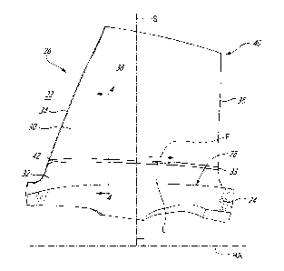
[0024] FIG. 3 is a side elevation view of an exemplary blade 26 of
IBR 20. Blade
26 is viewed in FIG. 3 along a direction normal to a plane containing both
rotation axis
RA and stacking line S. FIG. 3 also shows an axial cross-section of part of
hub 24 from
which blade 26 extends. Blade 26 may include airfoil 30 and root fillet 32
providing a
smooth transition between platform 28 of hub 24 and airfoil 30. Airfoil 30 may
be disposed
radially outward of root fillet 32. Root fillet 32 may define a concave outer
surface
extending from platform 28 of hub 24 to airfoil 30. Root fillet 32 and airfoil
30 may have a
surface continuity so that an outer surface of airfoil 30 and an outer surface
of root fillet
- 5 -
Date Recue/Date Received 2022-07-19
32 may be touching at one or more locations. In some embodiments, root fillet
32 and
airfoil 30 may have a tangent (angular) surface continuity at one or more
(e.g., all)
locations where outer surfaces of root fillet 32 and airfoil 30 meet along a
common edge
and that the tangent plane at each point along the common edge is equal for
both outer
surfaces. The common edge between root fillet 32 and airfoil 30 may also
correspond to
runout 33 of root fillet 32. In some embodiments, root fillet 32 may be a
circular fillet and
may be specified by one or more radii values. In various embodiments, root
fillet 32 may
have a uniform or a varied radius around blade 26.
[0025] Airfoil 30 may include leading edge 34 and trailing edge 36.
Leading edge
34 may be disposed forward of trailing edge 36 relative to the general
streamwise flow
direction F of air interacting with airfoil 30. Airfoil 30 may include
pressure side 38 and an
opposite suction side 40 (shown in FIG. 4).
[0026] Airfoil 30 may include streamwise groove 42 formed into an
exterior
surface of airfoil 30. Groove 42 may be entirely disposed outside of root
fillet 32. In other
words, groove 42 may not be part of root fillet 32. Groove 42 may be disposed
radially
outward of root fillet 32. In various embodiments, groove 42 may be
immediately adjacent
(e.g., adjoining) root fillet 32, or may be spaced apart from root fillet 32.
[0027] Groove 42 may have a longitudinal axis L and may extend
substantially
along the streamwise direction of the air being conveyed in gas path 22 and
interacting
with airfoil 30. In some embodiments, some or at least a majority of
longitudinal axis L
may be substantially parallel to the expected flow direction F at
corresponding axial
locations along rotation axis RA. In some embodiments, the expected flow
direction F of
air interacting with airfoil 30 in the region of groove 42 may be related
(e.g., parallel) to
the axial cross-sectional profile of platform 28 shown in FIG. 3. In some
embodiments,
the expected flow direction F of air interacting with airfoil 30 the region of
groove 42 may
be related (e.g., parallel) to runout 33 of root fillet 32. For example, in
some embodiments,
some or a majority of groove 42 may be parallel to runout 33 of root fillet
32.
[0028] The streamwise orientation of groove 42 may provide a desired
influence
on crack propagation while providing little or minimal influence on the flow
of air
interacting with airfoil 30. In other words, at least part(s) of groove 42 may
be oriented to
be streamlined in order to offer low resistance to the flow of air through
compressor 14.
- 6 -
Date Recue/Date Received 2022-07-19
For example, in some embodiments, some, a majority, or an entirety of groove
42 may
be parallel to the expected flow direction F of air (or of another working
fluid) interacting
with airfoil 30.
[0029] The expected flow direction F of air interacting with airfoil
30 may differ at
different axial and/or radial locations of airfoil 30 depending on the
geometric parameters
of IBR 20, and/or based on operating parameter(s). The expected flow direction
F
selected for the purpose of orienting groove 42 may be selected to obtain a
desired
performance at one or more operating conditions. In some embodiments, an axial
vector
component of longitudinal axis L of groove 42 may be greater than a radial
vector
component of longitudinal axis L of groove 42. Longitudinal axis L of groove
42 may also
have a lateral vector component (e.g., into or out of the page in FIG. 3) that
may be based
on the stagger angle of blade 26. Longitudinal axis L of groove 42 may be
linear or non-
linear.
[0030] In various embodiments, groove 42 may extend partially or
completely
around airfoil 30. In other words, groove 42 may extend partially or
completely around
stacking line S. For example, groove 42 may extend on pressure side 38 and/or
on
suction side 40 of airfoil 30. In some embodiments, groove 42 may wrap around
leading
edge 34 and/or trailing edge 36. In some embodiments, groove 42 may extend
continuously (e.g., be uninterrupted) around airfoil 30.
[0031] IBR 20 may be made from a suitable metallic material. In various
embodiments, IBR 20 may be made by casting, machining and/or using other
suitable
manufacturing process(es). For example, groove 42 may be cast with the
remainder of
IBR 20 or maybe formed a machining operation subsequent to casting. For
example, IBR
20, including groove 42 may be machined from a casting, forging or bar stock.
[0032] FIG. 4 is a cross-section view of part of the blade 26 and hub 24 of
FIG. 3
taken along line 4-4 in FIG. 3. Groove 42 may extend from pressure side 38 to
suction
side 40 of airfoil 30. In some embodiments, groove 42 may extend completely
around
airfoil 30. For example, pressure side 38 may include first groove segment
42A, and
suction side 40 may include second groove segment 42B where both first groove
segment 42A and second groove segment 42B are part of the same groove 42.
Alternatively, only one of pressure side 38 or suction side 40 may include
groove 42.
- 7 -
Date Recue/Date Received 2022-07-19
Alternatively, both pressure side 38 and suction side 40 may include
respective and
separate groove segments 42A, 42B in cases where groove 42 does not
continuously
extend from pressure side 38 to suction side 40. In some embodiments, airfoil
30 may
include groove segments 42A, 42B that are at different spanwise (e.g., radial)
locations
along airfoil 30.
[0033] Groove 42 may have any suitable cross-sectional profile and
size to
provide a desired stress concentration that provide the desired influence on
crack
propagation. In some embodiments, a cross-sectional profile of groove 42
transverse to
longitudinal axis L (shown in FIG. 3) of groove 42 may be a circular segment,
or may be
another suitable shape (e.g., U-shaped or V-shaped). Such circular segment may
be a
region (e.g., area A) of two-dimensional space that is bounded by an arc of a
circle and
by a chord connecting the endpoints of the arc. Groove 42 may have depth D
measured
from the outer surface of airfoil 30, and width W measured transversely to
longitudinal
axis L of groove 42. In some embodiments, depth D of groove 42 may be equal to
or less
than 50% of width W of groove 42. In some embodiments, depth D of groove 42
may be
equal to or greater than 1% of width W of groove 42. In some embodiments,
depth D of
groove 42 may be between 1% and 50% of width W of groove 42.
[0034] In various embodiments, groove 42 may have a uniform
(constant) or a
varied area along a length (longitudinal axis L) of groove 42. For example,
groove 42 may
have area A on pressure side 38 that is different from area A of groove 42 on
suction side
40. In some embodiments, area A of groove 42 on suction side 40 may be smaller
than
area A of groove 42 on pressure side 38 for preferred aerodynamic performance.
[0035] In various embodiments, groove 42 may have a uniform
(constant) or a
varied depth D along a length (longitudinal axis L) of groove 42. For example,
groove 42
may have depth D on pressure side 38 that is different from depth D of groove
42 on
suction side 40. In some embodiments, depth D of groove 42 on suction side 40
may be
smaller than depth D of groove 42 on pressure side 38.
[0036] In various embodiments, groove 42 may have a uniform
(constant) or a
varied width W along a length (longitudinal axis L) of groove 42. For example,
groove 42
may have width W on pressure side 38 that is different from width W of groove
42 on
- 8 -
Date Recue/Date Received 2022-07-19
suction side 40. In some embodiments, width W of groove 42 on suction side 40
may be
smaller than width W of groove 42 on pressure side 38.
[0037] In some embodiments, airfoil 30 may include a plurality of
groove
segments 42A, 42B connected together and having different cross-sectional
dimensions.
In some embodiments, airfoil 30 may include a plurality of disconnected groove
segments
42A, 42B that have the same or different cross-sectional dimensions.
[0038] Root fillet 32 may provide a transition between outer
platform 28 of hub 24
and airfoil 30. Root fillet 32 and airfoil 30 may have surface and optionally
also have
tangent continuity. Root fillet 32 may have a radial height H from platform 28
measured
radially relative to rotation axis RA. Radial height H may correspond to a
maximum radial
height of root fillet 32 from platform 28. Radial height H may be measured
from platform
28 to runout 33 of root fillet 32. Depending on the geometry of blade 26,
runout 33 may
not necessarily be at a uniform radial height H around airfoil 30. Runout 33
may define a
radially inner extremity of airfoil 30. Accordingly, groove 42 may be disposed
radially
outward of root fillet 32. In some embodiments, groove 42 and root fillet 32
may be
adjoining as shown in FIG. 3. In some embodiments, groove 42 may be radially
spaced
apart from root fillet 32 as shown by non-zero dimension G in FIG. 4. In
various
embodiments, groove 42 may be disposed anywhere along radial region RR of
airfoil 30.
Radial region RR may extend from radially outward from runout 33 of root
fillet 32 to a
distance of two or three times radial height H of root fillet 32. In other
words, groove 42
may be disposed radially outwardly of root fillet 32 and radially inwardly of
a distance of
two or three times (i.e., 2H or 3H) radial height H of root fillet 32 from
root fillet 32.
[0039] In some embodiments, every blade 26 of IBR 20 may each
include an
identical groove 42 to facilitate balancing of IBR 20. However, adequate
balancing IBR
20 may also be achieved in other embodiments where not every blade 26 includes
groove
42, or where some blades 26 of the same IBR 20 include grooves of different
configurations.
[0040] FIG. 5 is an axial cross-section view of part of another
exemplary
integrated bladed rotor including one or more exemplary blades 126 and
platform 128.
Blade 126 and platform 128 may include elements previously described above.
Like
elements have been identified using reference numerals incremented by 100.
Blade 126
- 9 -
Date Recue/Date Received 2022-07-19
may include airfoil 130 and root fillet 132 providing a smooth transition
between platform
128 of hub 124 and airfoil 130. Root fillet 132 may include runout 133 at the
intersection
of root fillet 132 and airfoil 130. Airfoil 130 may be disposed radially
outward of root fillet
132. Airfoil 130 may include leading edge 134 and trailing edge 136. Airfoil
130 may
include pressure side 138 and opposite suction side 140.
[0041] In some applications, the stresses at leading edge 134 of
airfoil 130 may
be relatively high, and may be higher than the stresses in other region(s) of
airfoil 130.
Leading edge 134 may also be more susceptible to impact by foreign objects
ingested by
engine 10. Accordingly, in some situations, it may be desirable to have
reduced or no
groove-associated stress concentrations at and/or near leading edge 134 of
airfoil 130.
In some embodiments, the configuration of groove 142 may differ at and/or near
leading
edge 134 than in other regions of airfoil 130. In some embodiments, groove 142
may be
smaller (e.g., smaller area A shown in FIG. 4) at and/or near leading edge 134
to provide
a reduced stress concentration factor at and/or near leading edge 134 relative
to other
regions of airfoil 130. In some embodiments, groove 142 may be interrupted at
and/or
near leading edge 134 of airfoil 130. In other words, airfoil 130 may be
devoid of groove
142 at and/or near leading edge 134 of airfoil 130.
[0042] FIG. 6 is an axial cross-section view of part of another
exemplary
integrated bladed rotor including one or more exemplary blades 226 and
platform 228.
Blade 226 and platform 228 may include elements previously described above.
Like
elements have been identified using reference numerals incremented by 200.
Blade 226
may include airfoil 230 and root fillet 232 providing a smooth transition
between platform
228 of hub 224 and airfoil 230. Root fillet 232 may include runout 233 at the
intersection
of root fillet 232 and airfoil 230. Airfoil 230 may be disposed radially
outward of root fillet
232. Airfoil 230 may include leading edge 234 and trailing edge 236. Airfoil
230 may
include pressure side 238 and opposite suction side 240. Airfoil 230 may also
include
exemplary chord C joining leading edge 234 and trailing edge 236 of airfoil
230.
[0043] In some applications, the stresses at a mid-chord region MC
of airfoil 230
may be relatively high, and may be higher than the stresses in other region(s)
of airfoil
230. Accordingly, in some situations, it may be desirable to have reduced or
no groove-
associated stress concentrations in mid-chord region MC of airfoil 230. In
some
embodiments, the cross-sectional profile of groove 242 may vary as a function
of a
- 10 -
Date Recue/Date Received 2022-07-19
position along chord C or as a function of an axial position along rotation
axis RA. In some
embodiments, the configuration of groove 242 may differ in mid-chord region MC
of airfoil
230 compared to other regions of airfoil 230. In some embodiments, groove 242
may be
smaller (e.g., smaller area A shown in FIG. 4) in mid-chord region MC of
airfoil 230 to
provide a reduced stress concentration factor in mid-chord region MC of
airfoil 230. In
some embodiments, groove 242 may be interrupted in mid-chord region MC of
airfoil 230.
In other words, airfoil 230 may be devoid of groove 242 in mid-chord region MC
of airfoil
230.
[0044] FIG. 7A is a schematic axial cross-section view of part of an
exemplary
integrated bladed rotor 20A (referred hereinafter as "IBR 20A") without crack-
mitigating
groove 42. FIG. 7B is a schematic axial cross-section view of part of IBR 20
with crack-
mitigating groove 42. In operation, compressor blades 26 may be subjected to a
steady
stress associated with low-cycle-fatigue (LCF) as a result of centrifugal and
thermal loads.
Compressor blades 26 may also be subjected to vibratory stresses associated
with high-
cycle-fatigue (HCF) occurring at resonance conditions for example. When the
useful life
of blade 26 is exhausted and a fatigue crack is initiated on airfoil 30 for
example, damage
tolerance methods and tools may be used to determine the remaining crack
propagation
life and trajectory of the crack leading up to failure. The trajectory of the
propagating crack
may be important for determining the potential size, shape, and mass of the
fragment that
will be released from IBR 20A, 20. For a crack that originates from airfoil
30, the resulting
fragment upon failure can be classified either as either a relatively benign
blade release
which may be contained by the casing of engine 10 surrounding IBR 20A, or as a
disc
rupture (i.e., large fragment) which may be more troublesome and may not be
contained
by the casing.
[0045] The trajectory of a propagating crack may be a function of the
combined
LCF-HCF stress field. Mathematically, the combined LCF-HCF stress field may be
represented as a vector summation of the individual LCF and HCF crack growth
contributions (e.g., LCF + ZHCF). In general, LCF loads dominated by radial
centrifugal
loading may tend to grow the crack parallel to gas path 22 (shown in FIGS. 1
and 3),
thereby promoting a containable blade release failure mode.
[0046] On the other hand, HCF loads may exhibit more complex stress
fields and
may occur at resonance conditions. For resonance modes with significant
airfoil-hub
- 11 -
Date Recue/Date Received 2022-07-19
participation, there is potential for the resulting dynamic stress field to
grow the crack into
hub 24. Even if the magnitude of the dynamic stresses are low in comparison to
the
steady stresses, the resulting modal frequency and accumulated HCF cycles may
amplify
the HCF vector (i.e., ZHCF). In such case, the resulting failure mode may be
an
uncontained disc rupture.
[0047] The addition of groove 42 in airfoil 30 radially outward of
root fillet 32 may
influence crack propagation by discouraging the crack originating on airfoil
30 from
growing into hub 24. In other words, the presence of groove 42 may influence
crack
propagation to promote a contained blade release as opposed to a disc rupture.
[0048] Groove 42 may serve this function by introducing stress
concentration
factor K in the radial flow stress direction as well as an increase in the
local nominal
stresses. This helps in favouring the LCF contribution of crack growth, which
is
predominately caused by radial stresses. Groove 42 may also amplify the radial
stress
contribution of the HCF stress field. Both these changes to the stress field
may favour a
blade release as opposed to a disc rupture.
[0049] Groove 42 may be used on compressor IBR 20 where the
resulting airfoil
steady stresses are low in comparison to dynamic stresses and the
corresponding LCF
lives are high. Groove 42 may be designed and positioned such that it does not
produce
a new critical lifing location and the minimum life of the IBR 20 is not
significantly altered.
For example, groove 42 may be added to airfoil 30 without altering a typical
or desired
root fillet geometry.
[0050] The embodiments described in this document provide non-
limiting
examples of possible implementations of the present technology. Upon review of
the
present disclosure, a person of ordinary skill in the art will recognize that
changes may
be made to the embodiments described herein without departing from the scope
of the
present technology. Further modifications could be implemented by a person of
ordinary
skill in the art in view of the present disclosure, which modifications would
be within the
scope of the present technology.
- 12 -
Date Recue/Date Received 2022-07-19