Note: Descriptions are shown in the official language in which they were submitted.
CA 03169631 2022-07-28
WO 2021/162888
PCT/US2021/016142
SHUNT SYSTEMS AND METHODS WITH TISSUE GROWTH PREVENTION
RELATED APPLICATION
[0001] This application claims priority to U.S. Provisional Application
No. 62/975,024, filed on February 11, 2020, entitled SHUNT SYSTEMS AND METHODS
WITH TISSUE GROWTH PREVENTION, the disclosure of which is hereby incorporated
by reference in its entirety.
BACKGROUND
[0002] The present invention relates generally to cardiac shunts and
systems and
methods of delivery, and in particular, to a shunt to reduce left atrial
pressure.
[0003] Heart failure is a common and potentially lethal condition
affecting
humans, with sub-optimal clinical outcomes often resulting in symptoms,
morbidity and/or
mortality, despite maximal medical treatment. In particular, "diastolic heart
failure" refers to
the clinical syndrome of heart failure occurring in the context of preserved
left ventricular
systolic function (ejection fraction) and in the absence of major valvular
disease. This
condition is characterized by a stiff left ventricle with decreased compliance
and impaired
relaxation, which leads to increased end-diastolic pressure. Approximately one
third of
patients with heart failure have diastolic heart failure and there are very
few, if any, proven
effective treatments.
[0004] Symptoms of diastolic heart failure are due, at least in a large
part, to an
elevation in pressure in the left atrium. Elevated Left Atrial Pressure (LAP)
is present in
several abnormal heart conditions, including Heart Failure (HF). In addition
to diastolic heart
failure, a number of other medical conditions, including systolic dysfunction
of the left
ventricle and valve disease, can lead to elevated pressures in the left
atrium. Both Heart
Failure with Preserved Ejection Fraction (HFpEF) and Heart Failure with
Reduced Ejection
Fraction (HFrEF) can exhibit elevated LAP. It has been hypothesized that both
subgroups of
HF might benefit from a reduction in LAP, which in turn reduces the systolic
preload on the
left ventricle, Left Ventricular End Diastolic Pressure (LVEDP). It could also
relieve pressure
on the pulmonary circulation, reducing the risk of pulmonary edema, improving
respiration
and improving patient comfort.
SUMMARY
[0005] For purposes of summarizing the disclosure, certain aspects,
advantages
and novel features have been described herein. It is to be understood that not
necessarily all
such advantages may be achieved in accordance with any particular embodiment.
Thus, the
1
Date Recue/Date Received 2022-07-28
CA 03169631 2022-07-28
WO 2021/162888
PCT/US2021/016142
disclosed embodiments may be carried out in a manner that achieves or
optimizes one
advantage or group of advantages as taught herein without necessarily
achieving other
advantages as may be taught or suggested herein.
[0006] Some implementations of the present disclosure relate to a shunt
comprising a central flow portion configured to fit at least partially within
an opening in a
tissue wall. The tissue wall is situated between a first anatomical chamber
and a second
anatomical chamber and the opening creates a blood flow path between the first
anatomical
chamber and the second anatomical chamber. The central flow portion is further
configured
to maintain the blood flow path from the first anatomical chamber to the
second anatomical
chamber. The shunt further comprises a barrier configured to alter growth of
tissue around
the shunt.
[0007] The shunt may further comprise one or more anchoring arms
extending
from the central flow portion. The one or more anchoring arms may be
configured to anchor
to the tissue wall.
[0008] In some embodiments, the barrier extends from at least one of the
one or
more anchoring arms. The barrier may comprise one or more spikes extending
from at least
one of the one or more anchoring arms.
[0009] In some embodiments, the one or more spikes have pointed ends.
The
barrier may comprise a first spike and a second spike. The first spike may be
configured to be
situated further from the opening than the second spike.
[0010] In some embodiments, the barrier extends from the central flow
portion.
The barrier may comprise a first portion configured to extend over a first
side of the tissue
wall. In some embodiments, the first portion is configured to extend at an
approximately 45-
degree angle over the first side of the tissue wall.
[0011] The barrier may comprise a second portion configured to extend
over a
second side of the tissue wall. In some embodiments, the first portion and the
second portion
form a single continuous device.
[0012] The opening may have an elliptical shape and the first portion
may form at
least a partial cone with a tapered elliptical shape in which the first
portion extends over a full
ellipse of tissue on the first side of the tissue wall. In some embodiments,
the first portion
does not extend over the opening.
[0013] A length of the first portion may be greater than a width and
thickness of
the first portion. In some embodiments, the first portion may have a shape of
an at least
partial elliptical ring with a hollow middle portion configured to be aligned
with the opening.
2
Date Recue/Date Received 2022-07-28
CA 03169631 2022-07-28
WO 2021/162888 PCT/US2021/016142
The shunt may further comprise one or more anchoring arms extending from the
central flow
portion. The one or more anchoring arms may be configured to anchor to the
tissue wall. In
some embodiments, the barrier extends from at least one of the one or more
anchoring arms.
The barrier may be configured to be situated between the one or more anchoring
arms and the
tissue wall. In some embodiments, the central flow portion is further
configured to prevent in-
growth of tissue within the opening. The central flow portion may be
configured to expand in
response to expansion of the tissue wall.
[0014] Some implementations of the present disclosure relate to a method
comprising creating an opening in a tissue wall, treating an area of tissue
around the opening
to prevent in-growth of tissue at the opening, and placing a shunt at the
opening.
[0015] The area of tissue may have an elliptical shape and completely
surround
the opening. In some embodiments, the shunt comprises a central flow portion
configured to
fit at least partially within an opening in a tissue wall.
[0016] The tissue wall may be situated between a first anatomical
chamber and a
second anatomical chamber and the opening may represent a blood flow path
between the
first anatomical chamber to the second anatomical chamber. The central flow
portion may be
further configured to maintain the blood flow path from the first anatomical
chamber to the
second anatomical chamber.
[0017] In some embodiments, the shunt further comprises a barrier
configured to
alter growth of tissue around the shunt. Treating the area of tissue may
involve burning the
area of tissue.
BRIEF DESCRIPTION OF THE DRAWINGS
[0018] Various embodiments are depicted in the accompanying drawings for
illustrative purposes and should in no way be interpreted as limiting the
scope of the
inventions. In addition, various features of different disclosed embodiments
can be combined
to form additional embodiments, which are part of this disclosure. Throughout
the drawings,
reference numbers may be reused to indicate correspondence between reference
elements.
However, it should be understood that the use of similar reference numbers in
connection
with multiple drawings does not necessarily imply similarity between
respective
embodiments associated therewith. Furthermore, it should be understood that
the features of
the respective drawings are not necessarily drawn to scale, and the
illustrated sizes thereof are
presented for the purpose of illustration of inventive aspects thereof.
Generally, certain of the
illustrated features may be relatively smaller than as illustrated in some
embodiments or
configurations.
3
Date Recue/Date Received 2022-07-28
CA 03169631 2022-07-28
WO 2021/162888 PCT/US2021/016142
[0019] Figure 1 illustrates several access pathways for maneuvering
guidewires
and/or catheters in and around the heart to deploy expandable shunts in
accordance with some
embodiments.
[0020] Figure 2 depicts a method for deploying expandable shunts in
accordance
with some embodiments.
[0021] Figure 3A is a side view of an opening through a tissue wall for
placement
of a shunt in the opening in accordance with some embodiments.
[0022] Figure 3B is a view from above (e.g., from the left atrium) of an
opening
through a tissue wall for placement of a shunt in the opening in accordance
with some
embodiments.
[0023] Figure 4 illustrates a shunt having one or more barrier walls to
prevent,
contain, and/or inhibit tissue growth at and/or around the shunt and/or an
opening in a tissue
wall in accordance with some embodiments.
[0024] Figure 5 illustrates a shunt having one or more barrier spikes to
prevent,
contain, and/or inhibit tissue growth in accordance with some embodiments.
[0025] Figure 6 illustrates a method of preventing, inhibiting, and/or
containing
tissue growth involving treating an area of tissue around an opening in
accordance with some
embodiments.
[0026] Figure 7 illustrates a shunt having an upper barrier to prevent,
contain,
and/or inhibit tissue growth in accordance with some embodiments.
[0027] Figures 8A illustrates a side-view of a shunt having a lower
barrier to
prevent, contain, and/or inhibit tissue growth in accordance with some
embodiments.
[0028] Figures 8B illustrates a view from above (e.g., from the left
atrium) of a
shunt having a lower barrier to prevent, contain, and/or inhibit tissue growth
in accordance
with some embodiments.
[0029] Figure 9 is a flow diagram of an example of a process for
delivering and/or
anchoring a shunt to a body of a person to in accordance with some
embodiments.
DETAILED DESCRIPTION
[0030] The headings provided herein are for convenience only and do not
necessarily affect the scope or meaning of the claimed invention.
Overview
[0031] In vertebrate animals, the heart is a hollow muscular organ
having four
pumping chambers: the left and right atria and the left and right ventricles,
each provided
with its own one-way valve. The natural heart valves are identified as the
aortic, mitral (or
4
Date Recue/Date Received 2022-07-28
CA 03169631 2022-07-28
WO 2021/162888
PCT/US2021/016142
bicuspid), tricuspid and pulmonary, and are each mounted in an annulus
comprising dense
fibrous rings attached either directly or indirectly to the atrial and
ventricular muscle fibers.
Each annulus defines a flow orifice. The four valves ensure that blood does
not flow in the
wrong direction during the cardiac cycle; that is, to ensure that the blood
does not back flow
through the valve. Blood flows from the venous system and right atrium through
the tricuspid
valve to the right ventricle, then from the right ventricle through the
pulmonary valve to the
pulmonary artery and the lungs. Oxygenated blood then flows through the mitral
valve from
the left atrium to the left ventricle, and finally from the left ventricle
through the aortic valve
to the aorta/arterial system.
[0032] Heart failure is a common and potentially lethal condition
affecting
humans, with sub-optimal clinical outcomes often resulting in symptoms,
morbidity and/or
mortality, despite maximal medical treatment. In particular, "diastolic heart
failure" refers to
the clinical syndrome of heart failure occurring in the context of preserved
left ventricular
systolic function (ejection fraction) and in the absence of major valvular
disease. This
condition is characterized by a stiff left ventricle with decreased compliance
and impaired
relaxation, which leads to increased end-diastolic pressure. Approximately one
third of
patients with heart failure have diastolic heart failure and there are very
few, if any, proven
effective treatments.
[0033] Symptoms of diastolic heart failure are due, at least in a large
part, to an
elevation in pressure in the left atrium. Elevated Left Atrial Pressure (LAP)
is present in
several abnormal heart conditions, including Heart Failure (HF). In addition
to diastolic heart
failure, a number of other medical conditions, including systolic dysfunction
of the left
ventricle and valve disease, can lead to elevated pressures in the left
atrium. Both Heart
Failure with Preserved Ejection Fraction (HFpEF) and Heart Failure with
Reduced Ejection
Fraction (HFrEF) can exhibit elevated LAP. It has been hypothesized that both
subgroups of
HF might benefit from a reduction in LAP, which in turn reduces the systolic
preload on the
left ventricle, Left Ventricular End Diastolic Pressure (LVEDP). It could also
relieve pressure
on the pulmonary circulation, reducing the risk of pulmonary edema, improving
respiration
and improving patient comfort.
[0034] Pulmonary hypertension (PH) is defined as a rise in mean pressure
in the
main pulmonary artery. PH may arise from many different causes, but, in all
patients, has
been shown to increase mortality rate. A deadly form of PH arises in the very
small branches
of the pulmonary arteries and is known as Pulmonary Arterial Hypertension
(PAH). In PAH,
the cells inside the small arteries multiply due to injury or disease,
decreasing the area inside
Date Recue/Date Received 2022-07-28
CA 03169631 2022-07-28
WO 2021/162888 PCT/US2021/016142
of the artery and thickening the arterial wall. As a result, these small
pulmonary arteries
narrow and stiffen, causing blood flow to become restricted and upstream
pressures to rise.
This increase in pressure in the main pulmonary artery is the common
connection between all
forms of PH regardless of underlying cause. Despite previous attempts, there
is a need for an
improved way to reduce elevated pressure in the left atrium, as well as other
susceptible heart
chambers such as the pulmonary artery.
[0035] The present disclosure provides methods and devices that may
allow for
elevated LAP to be reduced by shunting blood from a first anatomical chamber
(e.g., the left
atrium) to a second anatomical chamber (e.g., the coronary sinus). While some
embodiments
herein may be described with respect to treating LAP and/or similar issues,
the shunting
devices and methods described may be used to treat other issues, including
dialysis. Some
embodiments involve a shunt defining an open pathway between the left atrium
and the
coronary sinus, although the method can be used to place a shunt between other
cardiac
chambers, such as between the pulmonary artery and right atrium. The term
"shunt" is used
herein according to its broad and ordinary meaning and may include any
shunting means
and/or means for shunting blood between and/or from one anatomical chamber
and/or blood
pathway to another anatomical chamber and/or blood pathway. The shunt may be
configured
to prevent initial collapse of the open pathway while also preventing in-
growth of tissue at
least at an inner surface of the open pathway. In some embodiments, the shunt
may be
expandable so as to be compressed, delivered via a low-profile sheath or tube,
and expelled
so as to resume its expanded state. Some methods may also include utilizing a
deployment
catheter that may first create a puncture in a tissue wall between the left
atrium and the
coronary sinus. A catheter as described herein can include any delivery means
and/or means
for delivering one or more implants within a body of a patient.
[0036] Moreover, in some embodiments, a shunt may be configured to
expand
post-delivery in response to expansion of the tissue wall. For example, some
patients, and
particularly HF patients, may experience amyloidosis, which is a protein
disorder in which
amyloid deposits in the heart can make the heart walls stiffen and/or increase
in thickness.
Shunt implants having a maximum tissue wall thickness specification may not be
configured
to accommodate some levels of tissue growth/expansion. For example, some shunt
implants
may have wall thickness specifications of approximately 4mm. However, many
amyloidosis
patients can have tissue wall thickness that may continue to increase beyond
4mm, therefore
causing patency issues with shunt implants post-implantation. Accordingly, it
may be
advantageous for shunt implants to include features configured to present a
physical barrier to
6
Date Recue/Date Received 2022-07-28
CA 03169631 2022-07-28
WO 2021/162888 PCT/US2021/016142
tissue growth and/or for shunt implants to be delivered in association with
devices and/or
methods for preventing and/or inhibiting tissue growth. For example, a barrier
may include a
wall, spike, ring, or other device which may extend from and/or attach to a
shunt to prevent,
inhibit, and/or contain tissue growth at and/or around the shunt and/or the
opening in the
tissue wall. In some embodiments, shunt implants may also be at least
partially expandable
and/or configured to "grow" in response to tissue growth.
[0037] Shunt implants described herein may therefore include a central
flow
portion and/or anchoring arms that may be configured to attach to various
mechanical
elements configured to prevent and/or inhibit tissue growth. An anchoring arm
may include
any anchoring means and/or means for anchoring a shunt implant and/or portion
of a shunt
implant. In some embodiments, shunt implants may be delivered using methods
configured to
prevent and/or inhibit tissue growth around and/or near the shunt implants.
Shunt implants
may incorporate various mechanical systems to prevent and/or inhibit tissue
growth. Details
of these methods, implants and deployment systems will be described below.
[0038] Figure 1 illustrates several access pathways for maneuvering
guidewires
and catheters in and around the heart 1 to deploy expandable shunts of the
present
application. For instance, access may be from above via either the subclavian
vein 11 or
jugular vein 12 into the superior vena cava (SVC) 15, right atrium (RA) 5 and
from there into
the coronary sinus (CS) 19. Alternatively, the access path may start in the
femoral vein 13
and through the inferior vena cava (IVC) 14 into the heart 1. Other access
routes may also be
used, and each typically utilizes a percutaneous incision through which the
guidewire and
catheter are inserted into the vasculature, normally through a sealed
introducer, and from
there the physician controls the distal ends of the devices from outside the
body.
[0039] Figure 2 depicts a method for deploying various implants 10
including
expandable shunts described herein, wherein a catheter 16 is introduced
through the
subclavian or jugular vein, through the SVC 15 and into the coronary sinus 19.
Once a
guidewire provides a path, an introducer sheath may be routed along the
guidewire and into
the patient's vasculature, typically with the use of a dilator. Figure 2 shows
a deployment
catheter 16 extending from the SVC 15 to the coronary sinus 19 of the heart 1,
the
deployment catheter 16 having been passed through the introducer sheath which
provides a
hemostatic valve to prevent blood loss.
[0040] In one embodiment, the deployment catheter 16 may be about 30 cm
long,
and the guidewire may be somewhat longer for ease of use. In some embodiments,
the
deployment catheter may function to form and prepare an opening in the wall of
the left
7
Date Recue/Date Received 2022-07-28
CA 03169631 2022-07-28
WO 2021/162888 PCT/US2021/016142
atrium 2, and a separate placement or delivery catheter will be used for
delivery of an
expandable shunt. In other embodiments, the deployment catheter may be used as
the both
the puncture preparation and shunt placement catheter with full functionality.
In the present
application, the terms "deployment catheter" or "delivery catheter" will be
used to represent a
catheter or introducer with one or both of these functions.
[0041] Since the coronary sinus 19 is largely contiguous around the left
atrium 2,
there are a variety of possible acceptable placements for the stent. The site
selected for
placement of the stent, may be made in an area where the tissue of the
particular patient is
less thick or less dense, as determined beforehand by non-invasive diagnostic
means, such as
a CT scan or radiographic technique, such as fluoroscopy or intravascular
coronary echo
(IVUS).
[0042] Some methods to reduce LAP involve utilizing a shunt between the
left
atrium 2 and the right atrium 5, through the interatrial septum therebetween.
This is a
convenient approach, as the two structures are adjacent and transseptal access
is common
practice. However, there may be a possibility of emboli travelling from the
right side of the
heart to the left, which presents a stroke risk. This event should only happen
if the right
atrium pressures go above left atrium pressures; primarily during discrete
events like
coughing, sneezing, Valsalva maneuver, or bowel movements. The anatomical
position of the
septum would naturally allow emboli to travel freely between the atria if a
shunt was present
and the pressure gradient flipped. This can be mitigated by a valve or filter
element in the
shunt, but there may still be risk that emboli will cross over.
[0043] Shunting to the coronary sinus 19 offers some distinct
advantages,
primarily that the coronary sinus 19 is much less likely to have emboli
present for several
reasons. First, the blood draining from the coronary vasculature into the
right atrium 5 has
just passed through capillaries, so it is essentially filtered blood. Second,
the ostium of the
coronary sinus 19 in the right atrium 5 is often partially covered by a pseudo-
valve called the
Thebesian Valve. The Thebesian Valve is not always present, but some studies
show it is
present in >60% of hearts and it would act as a natural "guard dog" to the
coronary sinus to
prevent emboli from entering in the event of a spike in right atrium pressure.
Third, pressure
gradient between the coronary sinus 19 and the right atrium 5 into which it
drains is very low,
meaning that emboli in the right atrium 5 is likely to remain there. Fourth,
in the event that
emboli do enter the coronary sinus 19, there will be a much greater gradient
between the right
atrium 5 and the coronary vasculature than between the right atrium 5 and the
left atrium 2.
8
Date Recue/Date Received 2022-07-28
CA 03169631 2022-07-28
WO 2021/162888 PCT/US2021/016142
Most likely emboli would travel further down the coronary vasculature until
right atrium
pressure returned to normal and then the emboli would return directly to the
right atrium 5.
[0044] Some additional advantages to locating the shunt between the left
atrium 2
and the coronary sinus 19 is that this anatomy is less mobile than the septum
(it is more
stable), it thus preserves the septum for later transseptal access for
alternate therapies, and it
could potentially have other therapeutic benefits. By diverting left atrial
blood into the
coronary sinus 19, sinus pressures may increase by a small amount. This would
cause blood
in the coronary vasculature to travel more slowly through the heart,
increasing perfusion and
oxygen transfer, which would be more efficient and also could help a dying
heart muscle to
recover. There is a device designed to do this very thing, the Neovasc
Reducer. The
preservation of transseptal access also is a very significant advantage
because HF patients
often have a number of other comorbidities like Atrial Fibrillation (AF) and
Mitral
Regurgitation (MR) and several of the therapies for treating these conditions
require a
transseptal approach.
[0045] A shunt may also be positioned between other cardiac chambers,
such as
between the pulmonary artery and right atrium 5. The shunt may be desirably
implanted
within the wall of the pulmonary artery using the deployment tools described
herein, with the
catheters approaching from above and passing through the pulmonary artery. As
explained
above, pulmonary hypertension (PH) is defined as a rise in mean pressure in
the main
pulmonary artery. Blood flows through the shunt from the pulmonary artery into
the right
atrium 5 if the pressure differential causes flow in that direction, which
attenuates pressure
and reduces damage to the pulmonary artery. The purpose is to attenuate
pressure spikes in
the pulmonary artery. The shunt may also extend from the pulmonary artery to
other heart
chambers (e.g., left atrium 2) and/or blood vessels. Although not preferred or
shown, the
shunt may further contain a one-way valve for preventing backflow, or a check
valve for
allowing blood to pass only above a designated pressure. The present
application discloses a
new shunt for maintaining a flow path between chambers of the heart. Some
shunts described
herein may be at least partially expandable. Moreover, in some embodiments, a
shunt may
have various features and/or may be used in combination with devices having
various barriers
for preventing, inhibiting, and/or containing tissue growth. As used herein,
the term "barrier"
is used according to its broad and ordinary meaning and may include any
feature of a shunt
and/or configured to be used in conjunction with a shunt to at least partially
prevent, inhibit,
reduce, contain, and/or otherwise alter tissue growth at and/or around the
shunt. Shunts
described herein may have various features to simplify and/or improve delivery
procedures
9
Date Recue/Date Received 2022-07-28
CA 03169631 2022-07-28
WO 2021/162888
PCT/US2021/016142
for surgeons. For example, a shunt may be at least partially flexible,
compressible, and/or
elastic to allow the shunt to be shaped and/or molded as necessary/desired to
fit openings
and/or tissue walls having various sizes and/or shapes.
[0046] Figure 3A is a side view and Figure 3B is a view from above
(e.g., from
the left atrium 2) of an opening (i.e., puncture hole) 311 through a tissue
wall 308 (e.g.,
between the coronary sinus 19 and the left atrium 2) for placement of a shunt
in the opening
311. As shown in Figure 3A, a shunt deployment or delivery catheter 350 may be
advanced
to the tissue wall 308 between two chambers (e.g., the coronary sinus 19 and
the left atrium
2). A first side 301 of the tissue wall 308 may be situated on a side of a
first anatomical
chamber (e.g., the left atrium 2) and/or a second side 303 of the tissue wall
308 may be
situated on a side of a second anatomical chamber (e.g., the coronary sinus
19). The catheter
350 may have a soft and/or tapered distal tip 352. The delivery catheter 350
may be advanced
through the opening 311 in the tissue wall 308 into, for example, the left
atrium 2. The
opening may be created in any of a variety of ways. One example method is the
following.
[0047] Initially, a guidewire may be advanced, for example, from the
right atrium
into the coronary sinus 19 through its ostium or opening. A puncture catheter
may be
advanced over the guidewire. The puncture catheter may be introduced into the
body through
a proximal end of an introducer sheath. An introducer sheath may provide
access to the
particular vascular pathway (e.g., jugular or subclavian vein) and may have a
hemostatic
valve therein. While holding the introducer sheath at a fixed location, the
surgeon can
manipulate the puncture catheter to the implant site. A puncture sheath having
a puncture
needle with a sharp tip may be advanced along a catheter and punctured through
the
wall 308 into, for example, the left atrium 2. A puncture expander may be
advanced along the
guidewire and through the tissue wall 308 into the left atrium 2. The puncture
expander may
be, for example, an elongated inflatable balloon. The puncture expander may be
inflated
radially outward so as to widen the puncture through the tissue wall 308.
[0048] A shunt may be delivered through a lumen of the catheter 350.
During
delivery, the shunt may be in a collapsed configuration to facilitate
delivery. For example, the
shunt may be rolled, bent, twisted, and/or otherwise configured to have a
minimal profile to
facilitate delivery through the catheter 350. The shunt may be located in the
annular space
between an inner sheath and outer sheath of the catheter 350. An inner sheath
may be
retracted so that the shunt is placed in intimate engagement with the tissue
wall 308.
Radiopaque markers may be provided to facilitate positioning of the catheter
350 and/or
shunt. By creating an opening between the left atrium 2 and the coronary sinus
19, blood can
Date Recue/Date Received 2022-07-28
CA 03169631 2022-07-28
WO 2021/162888
PCT/US2021/016142
flow from the left atrium 2 (which is usually >8 mmHg) to the coronary sinus
19 (which is
usually <8 mmHg).
Shunt Implants
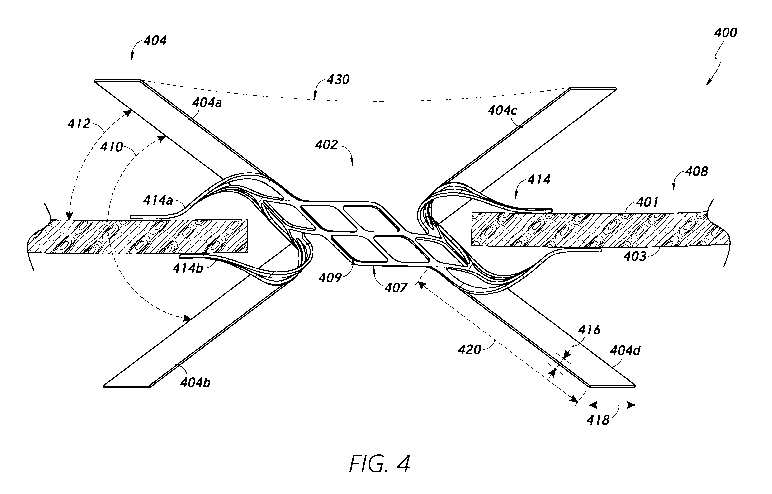
[0049] Figure 4 illustrates a shunt 400 having one or more barrier walls
404 to
prevent, contain, and/or inhibit tissue growth at and/or around the shunt 400
and/or an
opening in a tissue wall in accordance with some embodiments. As used herein,
the term
"barrier wall" may refer to any portion of a material configured to form a
barrier and/or
obstruction between at least a portion of tissue and at least a portion of a
shunt and/or
opening through a tissue wall 408. The shunt 400 may comprise any of a variety
of features
and/or components configured to maintain an opening in a tissue wall 408
and/or allow blood
flow through the tissue wall 408. In some embodiments, the shunt 400 may
comprise a
central flow portion 402 which may be configured to be situated at least
partially within the
opening in the tissue wall 408. In some embodiments, the shunt 400 may
comprise multiple
separate components which may be attached, connected, and/or otherwise joined
to form a
single device. For example, the central flow portion 402 may comprise multiple
components
to form a generally tubular shape which may approximate a shape of the opening
in the tissue
wall 408. For example, the opening may have a generally elliptical (e.g.,
circular) form (see,
e.g., Figure 3B) and the central flow portion 402 may be configured to form a
generally
cylindrical and/or tubular form to fit within and/or press against an inner
surface of the tissue
wall 408 at the opening.
[0050] The one or more walls 404 may be configured to extend outwardly
from
the central flow portion 402 and/or from one or more anchoring arms 414 of the
shunt 400.
For example, a wall 404 may extend from and/or attach to the central flow
portion 402,
however one or more walls 404 may extend from and/or attach to at least one of
the one or
more anchoring arms 414. In some embodiments, the one or more walls 404 may
extend
outwardly from the central flow portion 402 in a V-shape. For example, a first
wall 404a may
extend from the central flow portion 402 in a first direction (e.g., on a
first side 401 of the
tissue wall 408) and a second wall 404b may extend form the central flow
portion 402 in a
second direction (e.g., on a second side 403 of the tissue wall 408) to form a
first angle 410
between the first wall 404a and the second wall 404b. For example, the first
angle 410 may
be approximately ninety degrees. In some embodiments, a wall 404 may comprise
an
elongate sheet that may be bent at a middle portion of the wall 404 to form a
first portion
(i.e., the first wall 404a) and a second portion (i.e., the second wall 404b)
extending
outwardly from the central flow portion 402 in different directions with a the
first angle 410
11
Date Recue/Date Received 2022-07-28
CA 03169631 2022-07-28
WO 2021/162888 PCT/US2021/016142
of separation between the walls 404. Accordingly, the first wall 404a and the
second wall
404b may comprise a single continuous device.
[0051] In some embodiments, a wall 404 may comprise a sheet of material
having
a relatively small thickness 416 in comparison to a width 418 of the wall 404
and/or may
have a relatively small thickness 416 and/or width 418 in comparison to a
length 420 of the
wall 404. However, a wall 404 may have any thickness 416, width 418, and/or
length 420.
Each wall 404 may have a common thickness 416, width, and/or length 420 or
individual
walls 404 may have different thicknesses 416, widths, and/or lengths 420. As
shown in
Figure 4, the shunt 400 may comprise multiple distinct walls 404 with separate
and/or finite
widths 418. However, in some embodiments, a wall 404 may have a generally
conical shape
in which the width 418 of the wall 404 extends in a generally elliptical form
and forms a
complete or near-complete ellipse. For example, the first wall 404a and/or a
third wall 404c
may each extend in a non-linear manner until they join to generally form a
cone shape. For
example, a wall 404 may have a generally elliptical form in which the wall 404
forms a
complete or near complete ellipse of tissue over the tissue wall (e.g., a full
ellipse of tissue at
the first side 401 of the tissue wall 408). Accordingly, the first wall 404a
and the third wall
404c may extend laterally (e.g., along a first line 430) to form a single
continuous wall 404
(e.g., having an at least partial cone shape) around the first side 401 of the
tissue wall 408.
Similarly, the second wall 404b and the fourth wall 404d may extend to from a
single
continuous wall. Moreover, the wall 404 may have a generally tapered shape in
which a
diameter of the wall 404 increases as the wall 404 extends further from the
central flow
portion 402 and/or the opening. The wall 404 may only have a partial cone
shape because the
wall 404 may have a hollow middle portion configured to be aligned with the
opening in the
tissue wall 408. Accordingly, the wall 404 may not extend over the opening in
the tissue wall
408.
[0052] Moreover, the first wall 404a, second wall 404b, third wall 404c,
and a
third wall 404d may form a double cone or a partial double cone in which the
apex of the
double cone may be a true apex at or near the central flow portion 402 and/or
in which there
is no apex point but rather the double cone form of the wall 404 may have a
hollow middle
portion which approximates a tubular form of the central flow portion 402
and/or the opening
in the tissue wall 408.
[0053] A wall 404 may be configured to prevent, inhibit, and/or contain
tissue
growth around the shunt 400. Each wall 404 may extend outward form the central
flow
portion 402 over a portion of the tissue wall 408. For example, the first wall
404a may extend
12
Date Recue/Date Received 2022-07-28
CA 03169631 2022-07-28
WO 2021/162888 PCT/US2021/016142
over a portion of the first side 401 of the tissue wall 408. As shown in
Figure 4, the first wall
404a may extend at a second angle 412 from the first side 401 of the tissue
wall 408. In some
embodiments, the first wall 404a may extend in a generally parallel or
perpendicular direction
with respect to the tissue wall 408. While the first wall 404a and/or other
walls 404 are shown
having a generally linear form, each wall 404 may have a curvature and/or may
be bent at
various points as desired. A wall 404 may be configured to extend over the
tissue wall 408
(e.g., the first side 401 of the tissue wall 408) at any angle. For example,
the wall 404 may be
configured to extend such that the second angle 412 between the first wall
404a and the first
side 401 of the tissue wall is approximately 45-degrees.
[0054] In some embodiments, a wall 404 may be configured to at least
partially
penetrate and/or pass through the tissue wall 408. For example, a wall 404 may
extend
outwardly from the central flow portion 402 and into the tissue wall 408. The
wall 404 may
be partially embedded in the tissue wall 408 and/or a portion of the tissue
wall 408 may
extend out of the tissue wall 408.
[0055] As the tissue wall 408 increases in thickness and/or otherwise
expands
(e.g., grows inwardly towards the central flow portion 402), the tissue may
press against the
walls 404. The walls 404 may be composed of an at least partially solid
material and/or a
sufficiently densely interconnected network of materials that tissue growth
through the walls
404 may be prevented and/or at least partially inhibited.
[0056] Any of the one or more anchoring arms 414 may comprise one or
more
anchoring mechanisms, which may be situated, for example, at an end portion of
the
anchoring arm. Suitable anchoring mechanism may include any devices configured
to
penetrate and/or otherwise securely contact the tissue wall. For example, an
anchoring
mechanism may comprise one or more of a barb, a hook, a nail, and a screw.
When the shunt
400 is placed at the tissue wall 408, the anchoring mechanisms may be
configured to interact
with the tissue wall 408 to securely hold the shunt 400 in place.
[0057] Various features of the shunt 400, including the central flow
portion 402
and/or anchoring arms 414 described herein may be applied to the shunt devices
described
and/or illustrated in other figures of the present application. For example,
any description
with respect to the shunt 400 illustrated in Figure 4 may be similarly applied
to the shunt 500
in Figure 5, the shunt 700 in Figure 7, and the shunt 800 in Figures 8A and 8B
described
herein. Moreover, while other shunts shown and/or described with respect to
other figures
may not include walls 404 as shown in Figure 4, it will be understood that
walls 404 may be
added to the shunts described with respect to other figures. Similarly, the
various features
13
Date Recue/Date Received 2022-07-28
CA 03169631 2022-07-28
WO 2021/162888
PCT/US2021/016142
described with respect to other figures herein may be added to the shunt 400
of Figure 4
and/or other figures herein even if not depicted in and/or described with
respect to each
figure.
[0058] In some embodiments, the shunt 400 may be configured to be
movable
between an expanded configuration and a collapsed (e.g., generally tubular)
configuration to
facilitate passage through a lumen of a catheter. For example, the central
flow portion 402
may be configured to be rolled, bent, twisted, or otherwise compacted to fit
within the lumen
of the catheter. The central flow portion 402 may be configured to expand to a
pre-defined
shape and/or size during and/or after delivery within the body. The shunt 400
may further
comprise one or more anchoring arms 414, which may include flanges, arms,
anchors, and/or
other devices. The one or more anchoring arms 414 may be configured to at
least partially
collapse to facilitate passage through the lumen of the catheter and may be
configured to
expand during and/or after delivery within the body to contact and/or attach
to the tissue wall
408. Expansion of the shunt 400 may be initiated, for example, by retraction
of an outer
sheath of the catheter relative to an inner sheath. The shunt 400 may be
collapsed (e.g.,
crimped) into a generally tubular configuration between the two sheaths with
the anchoring
arms 414 straightened, and the anchoring arms 414 may be configured to spring
open when
the restraining outer sheath retracts. The anchoring arms 414 may expand
generally in
opposite direction in a common plane to form a T-shape, as opposed to
expanding in a
circular fashion. Radiopaque markers on the anchoring arms 414 may be provided
to
facilitate positioning immediately within the left atrium.
[0059] A pair of anchoring arms 414 (e.g., a first anchoring arm 414a
and a
second anchoring arm 414b) may foini a clamping (i.e., pinching) pair of
anchoring arms.
The pairs of anchoring arms 414 may be configured to apply a compressive force
to the tissue
wall 408 to hold the shunt 400 in place. The amount of compressive force may
be relatively
small to avoid damage to the tissue wall 408 while sufficient to hold the
shunt 400 in place.
For example, gaps separating the pairs of anchoring arms may be calibrated to
avoid
excessive clamping and/or necrosis of the tissue. The anchoring arms 414 may
be configured
to secure the shunt 400 on generally opposite sides of the tissue wall 408
(e.g., the first
anchoring arm 414a on a first side 401 of the tissue wall 408 and the second
anchoring arm
414b on a second side 403 of the tissue wall 408) and/or on generally opposite
sides of the
opening in the tissue wall 408. The central flow portion 402 may be configured
to be aligned
generally perpendicular to the tissue wall 408 so as to maintain an open flow
path between
14
Date Recue/Date Received 2022-07-28
CA 03169631 2022-07-28
WO 2021/162888 PCT/US2021/016142
the chambers on either side of the tissue wall 408 (e.g., the coronary sinus
and the left
atrium).
[0060] Components of the shunt 400 may be configured to naturally self-
expand
due to inherent springiness and/or flexibility of the components. For example,
various
components (e.g., the central flow portion 402, anchoring arms 414, and/or
walls 404) may
be composed of an elastic material such as Nitinol. In some embodiments, the
central flow
portion 402 may be fabricated by laser cutting a Nitinol tube. The central
flow portion 402
may have a wall thickness of between about 0.1-0.3mm.
[0061] As shown in Figure 4, the central flow portion 402 may be
composed of
generally thin struts 407 in a generally parallelogram arrangement that may
form an array of
parallelogram-shaped cells 409 or openings. However, the central flow portion
402, including
the struts 407 and/or cells 409, may have any shape, size, and/or orientation.
For example, the
struts 407 may have a generally thicker design than shown in Figure 4 to
minimize the size of
the cells 409, thereby further preventing in-growth of tissue through the
central flow portion
402. Rather than a generally parallelogram shape, the cells 409 may have a
generally
elliptical, triangular, hexagonal, or other shape. Moreover, the central flow
portion 402 may
not comprise any cells 409. In some embodiments, the shape of the struts 407,
cells 409,
and/or the central flow portion 402 generally may facilitate a collapsibility
and/or
expandability of the central flow portion 402 for passage through a lumen of a
catheter.
[0062] The flow portion 402 may be configured to form a generally
cylindrical or
other shape to approximate a shape of the opening. In some embodiments, the
opening may
be widened in all directions approximately evenly from a puncture point to
form an
approximately circular opening having a certain diameter. Accordingly, the
flow portion 402,
including the struts 407, may have an at least partially rounded and/or
circular form
around/about the opening along a longitudinal axis (i.e., into the opening).
[0063] In some embodiments, the expandable shunt 400 may be in a
compacted
and/or otherwise expandable form at delivery. For example, at delivery, the
central flow
portion 402, anchoring arms 414, and/or walls 404 may be folded, bent, and/or
otherwise
compacted to have a minimal profile to facilitate passage through a delivery
catheter. After
delivery, the central flow portion 402, anchoring arms 414, and/or walls 404
may be
configured to unfold, unwrap, and/or otherwise expand (e.g., to form the
design shown in
Figure 4). In some embodiments, at least a portion of the central flow portion
402, anchoring
arms 414, and/or walls 404 may be composed of Nitinol and/or a similar
material having
Date Recue/Date Received 2022-07-28
CA 03169631 2022-07-28
WO 2021/162888 PCT/US2021/016142
shape-memory characteristics such that the shunt 400 may naturally assume a
pre-determined
form after removal from the delivery catheter.
[0064] Moreover, the central flow portion 402 and/or anchoring arms 414
may be
configured to expand in response to growth and/or expansion of the tissue wall
408. For
example, as the tissue wall 408 expands (i.e., thickens), the first anchoring
arm 414a and the
second anchoring arm 414b may be configured to separate further from each
other to some
extent to accommodate the growth of the tissue wall 408. In some embodiments,
the central
flow portion 402, anchoring arms 414, and/or walls 404 may be configured to
stretch in
response to expansion of the tissue wall 408. For example, the central flow
portion 402,
anchoring arms 414, and/or walls 404 may be at least partially composed of a
flexible and/or
elastic material that may allow for some amount of stretching. As the tissue
wall 408
expands, the shunt 400 may be configured to stretch to accommodate the
expansion of the
tissue wall 408.
[0065] While each of Figures 4-8 may illustrate medical implants and/or
processes including features for preventing, containing, and/or inhibiting
tissue growth at or
near medical implants, these features may be used independently of each other
or in
combination with each other. For example, a shunt 400 as shown in Figure 4 may
include
walls 404 for managing tissue growth without any additional features for
managing tissue
growth. Alternatively, for example, the walls 404 and/or other features
describes herein may
be utilized in combination with other features. For example, the shunt 400 may
comprise one
or more spikes (as shown in Figure 5) and/or barriers (as shown in Figures 7
and 8) extending
from the walls 404 and/or other areas of the shunt 400. As another example,
the tissue wall
408 may be treated (as shown in Figure 6) prior to delivery of the shunt 400
and/or any other
shunt described herein.
[0066] Figure 5 illustrates a shunt 500 having one or more barrier
spikes 504 to
prevent, contain, and/or inhibit tissue growth in accordance with some
embodiments. The
shunt 500 may comprise a central flow portion 502 and/or one or more anchoring
arms 514,
similar to the central flow portion 502 and anchoring arms 514 described above
with respect
to Figure 4. Anchoring arms 514 may be configured to extend from the central
flow portion
502 to contact and/or attach to a first side 501 and/or second side 503 of the
tissue wall 508.
[0067] The shunt 500 may further comprise one or more spikes 504, which
may
include needles, rods, bumps, and/or other protuberances which may extend from
anchoring
arms 514 and/or the central flow portion 502. While Figure 5 shows two spikes
504
extending from each anchoring arm 514, any number of spikes 504 may extend
from an
16
Date Recue/Date Received 2022-07-28
CA 03169631 2022-07-28
WO 2021/162888 PCT/US2021/016142
anchoring arm 514 and/or one or more spikes 504 may extend from the central
flow portion
502. In some embodiments, a spike 504 may be composed of a different material
than the
anchoring arms 514 and/or central flow portion 502 and/or a spike 504 may
represent a
separate component from the anchoring arms 514 and/or central flow portion 502
and may be
attached to the anchoring arms 514 and/or central flow portion 502.
[0068] In some embodiments, a spike 504 may be a generally thin device
which
may have a base portion 505 that is in contact with an anchoring arm 514
and/or central flow
portion 502. From the base portion 505, the spike 504 may extend to an end
portion 507. In
some embodiments, a distance from the base portion 505 to the end portion 507
(i.e., a length
of the spike 504) may exceed a thickness of the spike 504. However, a spike
504 may have
any thickness and a length of the spike 504 may be less than a thickness of
the spike 504.
While the spikes 504 are shown extending generally perpendicularly to the
tissue wall 508,
the spikes 504 may extend from the shunt 500 and/or from the tissue wall 508
at any angle.
For example, a spike 504 may extend in a diagonal direction away from or
towards the
central flow portion 502 and/or opening.
[0069] The end portion 507 of a spike 504 may be generally pointed,
rounded,
and/or may have any other shape. In some embodiments, the end portion 507 may
be
sufficiently pointed that the end portion 507 may be capable of piercing
tissue. For example,
as a tissue wall 508 grows/expands, tissue may extend at least partially over
an anchoring arm
514 and/or the central flow portion 502. As the tissue encounters a spike 504,
the spike 504
may be sufficiently rigid that the tissue is not able to push through the
spike 504 and may be
required to grow over the spike 504. As the tissue extends over the end
portion 507 of the
spike 504, the end portion 507 may be configured to pierce and/or press
against the tissue to
cause the tissue to recede and/or stop growing over the shunt 500 in at least
one direction.
[0070] In some embodiments, spikes 504 may be positioned in multiple
levels.
For example, a first spike 504a may be positioned near a distal end of an
anchoring arm 514
(i.e., distal from the central flow portion 502) and a second spike 504b may
be positioned
near the central flow portion 502. That is, the first spike 504a may be
further from the central
flow portion 502 and/or the opening than the second spike 504b. As the tissue
wall 508
grows/expands, tissue may encounter the second spike 504b after passing over
the first spike
504a.
[0071] A spike 504 may have various features for piercing and/or
otherwise
inhibiting tissue growth. For example, a spike 504 may include multiple
smaller spikes which
may extend generally perpendicularly from the spike 504. Accordingly, as
tissue grows over
17
Date Recue/Date Received 2022-07-28
CA 03169631 2022-07-28
WO 2021/162888
PCT/US2021/016142
the spike 504, the smaller spikes may pierce and/or press against the tissue
to represent an
additional barrier to the tissue. Similarly, a spike 504 may have a ridged
surface and/or may
be coated in a sand-like or similar abrasive material to present an obstacle
to tissue growth.
[0072] Various embodiments and/or features of embodiments described
herein
may be combined. For example, one or more spikes 504 may extend from a wall
404
described herein with respect to Figure 4.
[0073] Figure 6 illustrates a method of preventing, inhibiting,
reducing, and/or
containing tissue growth involving treating one or more areas 604 of tissue
around and/or
near an opening 611 through a tissue wall 608 in accordance with some
embodiments. The
method may involve burning, cutting, removing, cauterizing, scarring, and/or
otherwise
treating the one or more areas 604 of tissue. An area 604 of tissue may
comprise a portion of
an outer surface of a tissue wall 608 (e.g., on a left atrium side or coronary
sinus side of the
tissue wall 608) and/or on an inner surface of the tissue wall 608 (e.g.,
within the opening 611
in the tissue wall 608).
[0074] In some embodiments, one or more areas 604 of tissue may be
treated
prior to, during, and/or after placement of a shunt at or near the opening
611. Various tools
may be delivered for use in treating one or more areas 604 of tissue. For
example, a laser or
similar device may be used to remove and/or burn the area 604 of tissue.
Treatment of the
one or more areas 604 may involve electrical ablation and/or use of an
electrical cauterizing
tool to cause a controlled scarring pattern and/or block electrical
transmission at an area 604
of tissue.
[0075] As shown in Figure 6, the area 604 may have an elliptical (e.g.,
circular)
shape and/or may approximate a shape of the opening 611 in the tissue wall
608. For
example, the opening 611 may have a generally circular shape having a first
radius 609 and
the area 604 may similarly have a generally circular shape having a second
radius 610 which
may be greater than the first radius 609. However, the one or more areas 604
may have any
size and/or shape. For example, an area 604 may not comprise a complete
ellipse and may
instead comprise a linear, jagged, curved, non-linear, etc. shape that may be
situated at or
near an anchoring location of a shunt implant. In some embodiments, multiple
areas 604 may
be created. For example, multiple elliptical or semi-elliptical areas 604
having different sizes
and/or radii may form an elliptical or other shape. The one or more areas 604
may represent
multiple levels of treated tissue along a lateral axis extending from the
opening 611. For
example, a first area 604 of tissue may have a wavy shape in which the first
area 604 overlaps
itself one or more times along a single axis extending from the opening 611.
In another
18
Date Recue/Date Received 2022-07-28
CA 03169631 2022-07-28
WO 2021/162888
PCT/US2021/016142
example, a first area 604 may be positioned a first distance along a lateral
axis from the
opening 611 and a second area 604 may be positioned a second distance along
the lateral axis
from the opening 611, in which the second distance is greater than the first
distance. In other
words, the second area 604 may be positioned distal to the opening 611 and the
first area 604
may be positioned proximal to the opening 611. In some embodiments, an area
604 may have
any thickness 606 and/or may have a gap 612 of any size between the opening
611 and the
area 604.
[0076] In some embodiments, an area 604 may be treated in conjunction
with
delivery of a shunt as described herein. A shunt may be placed at least
partially within the
opening 611. The shunt may have one or more anchoring arms configured to
extend over
and/or contact the tissue wall 608 around the opening 611. In some
embodiments, an
anchoring arm of a shunt may be configured to extend over an area 604 or not
extend beyond
the gap 612 between the opening 611 and the area 604. The shape and/or size of
an area 604
may be selected based on a shape and/or size of a shunt placed at the opening
611. For
example, before and/or after a shunt is placed, an area 604 shaped to closely
surround at least
a portion of the shunt may be treated. In this way, the area 604 may be
configured to prevent
growth and/or in-growth of tissue at and/or around the shunt.
[0077] Figure 7 illustrates a shunt 700 having an upper barrier 704 to
prevent,
contain, and/or inhibit tissue growth in accordance with some embodiments. In
some
embodiments, the upper barrier 704 may have an elliptical and/or torus shape.
The upper
barrier 704 may form a complete or partial ring around a hollow middle portion
of the ring.
The hollow middle portion may be configured to be aligned with the opening in
the tissue
wall 708 and/or a flow path created and/or maintained by a central flow
portion 702 of the
shunt 700. For example, the central flow portion 702 may define a flow path
through a tissue
wall 708 and the upper barrier 704 may be configured to surround but not
obstruct (or only
partially obstruct) the flow path.
[0078] Because Figure 7 shows a cross-sectional view of the shunt 700,
the upper
barrier 704 is shown as having a partial elliptical shape. However, the upper
barrier 704 may
form a complete ellipse around the opening in the tissue wall 808. The upper
barrier 704 may
have any shape. For example, the upper barrier 704 may have a rectangular,
triangular,
pentagonal, octagonal, or other shape and/or may include a hole through a
middle portion of
the upper barrier 704 to allow flow through the upper barrier 704.
[0079] While the upper barrier 704 is shown having a generally thin
structure, the
upper barrier 704 may have any thickness 706. Moreover, the upper barrier 704
may have a
19
Date Recue/Date Received 2022-07-28
CA 03169631 2022-07-28
WO 2021/162888 PCT/US2021/016142
varying thickness 706. For example, the upper barrier 704 may have an at least
partially
rounded surface in which a cross section of the upper barrier 704 would have
an ellipse
shape, similar to a torus.
[0080] In some embodiments, the upper barrier 704 may be configured to
extend
from and/or attach to the central flow portion 702 and/or to one or more
anchoring arms 714
of the shunt 700. For example, the upper barrier 704 may attach to and/or
extend from a first
anchoring arm 714a and/or a second anchoring arm 714b. The first anchoring arm
714a and
the second anchoring arm 714b may be situated on generally opposite sides of
the opening on
a first side 701 of the tissue wall 708 (or a second side 703 of the tissue
wall 708). In some
embodiments, the upper barrier 704 may represent a portion of the shunt 700
that is furthest
from the first side 701 of the tissue wall 708 and/or the second side 703 of
the tissue wall
708.
[0081] While only a single upper barrier 704 is shown in Figure 7, the
shunt 700
may comprise multiple upper barriers 704. For example, the shunt 700 may
comprise a
second upper barrier 704 extending from and/or attaching to the central flow
portion 702
and/or one or more anchoring arms 714 at the second side 703 of the tissue
wall 708.
Moreover, while the upper barrier 704 is shown extending from and/or attaching
to one or
more proximal portions 716 of the anchoring arms 714, the upper barrier 704
may be
configured to extend from and/or attach to any portion(s) of the anchoring
arms 714 and/or
central flow portion 702. For example, the upper barrier 704 may be configured
to attach to
and/or extend from one or more end portion 718 of the anchoring arms 714. In
some
embodiments, the hole in the middle portion of the upper barrier 704 may be
sufficiently
large that one or more proximal portions 716 of the anchoring arms 714 may be
configured to
fit into and/or through the hole when the upper barrier 704 is configured to
extend from
and/or attach to the end portions 718 of the anchoring arms 714.
[0082] While the upper barrier 704 is shown having a generally flat
structure, the
upper barrier 704 may have any shape and/or size. For example, the upper
barrier 704 may
have a generally wavy structure in which a high point (i.e., peak) of the
upper barrier 704 is
configured to fit over a proximal portion 716 of an anchoring arm and a low
point (i.e.,
trough) of the upper barrier 704 is configured to be situated close to and/or
to press against
the tissue wall 708. In some embodiments, the upper barrier 704 may be
composed of a
generally flexible and/or elastic material such that the upper barrier 704 may
be configured to
at least partially bend around portions of the anchoring arms 714 and/or
central flow portion
702 to fit closely to the anchoring arms 714 and/or central flow portion 702
and/or to
Date Recue/Date Received 2022-07-28
CA 03169631 2022-07-28
WO 2021/162888
PCT/US2021/016142
minimize gaps around and/or through the anchoring arms 714 and/or central flow
portion
702. For example, the upper barrier 704 may have a generally soft structure
and/or may be
configured to approximate contours of the anchoring arms 714 and/or central
flow portion
702 and/or to approximate a general shape of the anchoring arms 714 and/or
central flow
portion 702 when placed and/or situated on top of the anchoring arms 714
and/or central flow
portion 702. In some embodiments, the upper barrier 704 may be sufficiently
rigid in
structure that it may at least partially resist growth and/or expansion of the
tissue wall 708.
[0083] Figures 8A and 8B illustrate a shunt 800 having a lower barrier
804 to
prevent, contain, reduce, and/or inhibit tissue growth in accordance with some
embodiments.
Figure 8A provides a side-view of the shunt 800 and Figure 8B provides a view
of the shunt
800 from above (e.g., from the left atrium). In some embodiments, the lower
barrier 804 may
have an elliptical and/or torus shape. The lower barrier 804 may form a
complete ring around
a central hole, which may align with a flow path created and/or maintained by
a central flow
portion 802 of the shunt 800. For example, the central flow portion 802 may
define a flow
path through a tissue wall 808 and the upper barrier 804 may be configured to
surround but
not obstruct (or only partially obstruct) the flow path.
[0084] Because Figure 8A shows a cross-sectional view of the shunt 800,
the
lower barrier 804 is shown as having a partial elliptical shape. However, the
lower barrier
804 may form a complete ellipse around the opening in the tissue wall 808. The
lower barrier
804 may have any shape. For example, the lower barrier 804 may have a
rectangular,
triangular, pentagonal, octagonal, or other shape and/or may include a hole
through a middle
portion of the lower barrier 804 to allow flow through the lower barrier 804.
[0085] The lower barrier 804 may be configured to be situated between
one or
more anchoring arms 814 and the tissue wall 808. For example, one or more
anchoring arms
814 may be configured to press the lower barrier 804 against the tissue wall
808. While the
lower barrier 804 is shown having a generally thin structure, the lower
barrier 804 may have
any thickness. Moreover, the lower barrier 804 may have a varying thickness.
For example,
the lower barrier 804 may have an at least partially rounded surface in which
a cross section
of the lower barrier 804 would have an ellipse shape, similar to a torus.
[0086] In some embodiments, the lower barrier 804 may be configured to
extend
from and/or attach to the central flow portion 802 and/or to one or more
anchoring arms 814
of the shunt 800. For example, the lower barrier 804 may attach to and/or
extend from a first
anchoring arm 814a and/or a second anchoring arm 814b. The first anchoring arm
814a and
the second anchoring arm 814b may be situated on generally opposite sides of
the opening
21
Date Recue/Date Received 2022-07-28
CA 03169631 2022-07-28
WO 2021/162888 PCT/US2021/016142
811 on a first side 801 of the tissue wall 808 (or a second side 803 of the
tissue wall 808). In
some embodiments, the central flow portion 802 and/or anchoring arms 814 may
be
configured to hold the lower barrier 804 in place by pressing the lower
barrier 804 against the
tissue wall 808. Additionally or alternatively, the lower barrier 804 may have
various features
configured to interact with the tissue wall 808 to hold the lower barrier 804
in place. For
example, the outer surface of the lower barrier 804 may have a ridged and/or
contoured
structure configured to grip and/or penetrate the surface of the tissue wall
808. In another
example, the lower barrier 804 may comprise one or more nails, screws, hooks,
barbs, and/or
other features configured to attach to and/or penetrate the tissue wall to
securely hold the
lower barrier 804 in place. In some embodiments, anchoring elements (e.g.,
nails, screws,
hooks, barbs) may be separately delivered for anchoring the lower barrier 804
to the tissue
wall 808.
[0087] While only a single lower barrier 804 is shown in Figures 8A and
8B, the
shunt 800 may comprise multiple lower barriers 804. For example, the shunt 800
may
comprise a second lower barrier 804 pressed against the second side 803 of the
tissue wall
808. The lower barrier(s) 804 may have a sufficiently rigid structure to
oppose and/or resist
growth of tissue at and/or around the lower barrier 804.
Delivery Processes
[0088] Figure 9 is a flow diagram of an example of a process 900 for
delivering
and/or anchoring a shunt to a body of a person to in accordance with some
embodiments. In
block 902, the process 900 involves creating an opening in a tissue wall. As
described herein,
the opening may be created through use of one or more of a guidewire, puncture
catheter,
introducer sheath, puncture sheath, and/or puncture expander. The opening may
create a
blood flow path between two anatomical chambers (e.g., the left atrium and the
coronary
sinus). The opening may be created in any of a variety of ways. One example
method is the
following.
[0089] Initially, a guidewire may be advanced, for example, from the
right atrium
into the coronary sinus through its ostium or opening. A catheter may be
advanced over the
guidewire. The catheter may be introduced into the body through a proximal end
of an
introducer sheath. An introducer sheath may provide access to the particular
vascular
pathway (e.g., jugular or subclavian vein) and may have a hemostatic valve
therein. While
holding the introducer sheath at a fixed location, the surgeon can manipulate
the puncture
catheter to the implant site. A puncture sheath having a puncture needle with
a sharp tip may
be advanced along a catheter and punctured through the wall into, for example,
the left
22
Date Recue/Date Received 2022-07-28
CA 03169631 2022-07-28
WO 2021/162888 PCT/US2021/016142
atrium. A puncture expander may be advanced along the guidewire and through
the tissue
wall into the left atrium. The puncture expander may be, for example, an
elongated inflatable
balloon. The puncture expander may be inflated radially outward so as to widen
the puncture
through the tissue wall. In some embodiments, the opening may have a generally
circular
shape.
[0090] An implant may be delivered through a lumen of the catheter.
During
delivery, the implant may be in a collapsed configuration to facilitate
delivery. For example,
the implant may be bent, twisted, and/or otherwise configured to have a
minimal profile to
facilitate delivery through the catheter. The implant may be located in the
annular space
between an inner sheath and outer sheath of the catheter. An inner sheath may
be retracted so
that the implant is placed in intimate engagement with the tissue wall.
Radiopaque markers
may be provided to facilitate positioning of the catheter and/or implant. By
creating an
opening between the left atrium and the coronary sinus, blood can flow from
the left atrium
(which is usually >8 mmHg) to the coronary sinus (which is usually <8 mmHg).
One or more
implants may be delivered and/or anchored to a first side and/or to a second
side of the tissue
wall 808.
[0091] In block 904, the process 900 involves preparing an area of
tissue around
the opening. In some embodiments, preparing the tissue may involve burning,
scarring,
and/or otherwise treating the tissue to prevent, inhibit, and/or contain
tissue growth at and/or
around the area of tissue. In some embodiments, the treated area may
completely surround
the opening in the tissue wall. For example, the treated area may fix in a
circular (or other
shape) area around the opening such tissue growth around the entire opening
may be
managed.
[0092] In block 906, the process 900 involves attaching a shunt to a
delivery
catheter. The shunt may be crimped onto an outer surface of the catheter
and/or within a
lumen of the delivery catheter and/or may be in a collapsed state during
delivery. In some
embodiments, the shunt may be configured to be situated between an outer
surface of the
catheter and a delivery sheath configured to at least partially cover the
shunt. The sheath may
be configured to at least partially prevent expansion of the shunt during
delivery through
various pathways of the body.
[0093] In block 908, the process 900 involves advancing the delivery
catheter to
and/or near the opening. In some embodiments, the shunt may be configured to
at least
partially bend to facilitate delivery to and/or near the opening. For example,
the catheter
23
Date Recue/Date Received 2022-07-28
CA 03169631 2022-07-28
WO 2021/162888 PCT/US2021/016142
and/or shunt may be at least partially bent to maneuver the catheter into the
coronary sinus
ostium and/or into the opening.
[0094] In block 910, the process 900 involves placing the shunt into
and/or
around the opening. For example, the shunt may comprise a flow portion and/or
tube
configured to be situated within the opening and/or one or more anchoring
mechanisms
configured to anchor the flow portion to portions of the tissue wall outside
the opening. In
some embodiments, the shunt may comprise various barriers configured to
prevent, inhibit,
reduce, and/or contain growth of tissue around the opening and/or around the
shunt.
Additional Embodiments
[0095] Depending on the embodiment, certain acts, events, or functions
of any of
the processes or algorithms described herein can be performed in a different
sequence, may
be added, merged, or left out altogether. Thus, in certain embodiments, not
all described acts
or events are necessary for the practice of the processes.
[0096] Conditional language used herein, such as, among others, "can,"
"could,"
"might," "may," "e.g.," and the like, unless specifically stated otherwise, or
otherwise
understood within the context as used, is intended in its ordinary sense and
is generally
intended to convey that certain embodiments include, while other embodiments
do not
include, certain features, elements and/or steps. Thus, such conditional
language is not
generally intended to imply that features, elements and/or steps are in any
way required for
one or more embodiments or that one or more embodiments necessarily include
logic for
deciding, with or without author input or prompting, whether these features,
elements and/or
steps are included or are to be performed in any particular embodiment. The
terms
"comprising," "including," "having," and the like are synonymous, are used in
their ordinary
sense, and are used inclusively, in an open-ended fashion, and do not exclude
additional
elements, features, acts, operations, and so forth. Also, the term "or" is
used in its inclusive
sense (and not in its exclusive sense) so that when used, for example, to
connect a list of
elements, the term "or" means one, some, or all of the elements in the list.
Conjunctive
language such as the phrase "at least one of X, Y and Z," unless specifically
stated otherwise,
is understood with the context as used in general to convey that an item,
term, element, etc.
may be either X, Y or Z. Thus, such conjunctive language is not generally
intended to imply
that certain embodiments require at least one of X, at least one of Y and at
least one of Z to
each be present.
[0097] It should be appreciated that in the above description of
embodiments,
various features are sometimes grouped together in a single embodiment,
Figure, or
24
Date Recue/Date Received 2022-07-28
CA 03169631 2022-07-28
WO 2021/162888 PCT/US2021/016142
description thereof for the purpose of streamlining the disclosure and aiding
in the
understanding of one or more of the various inventive aspects. This method of
disclosure,
however, is not to be interpreted as reflecting an intention that any claim
require more
features than are expressly recited in that claim. Moreover, any components,
features, or steps
illustrated and/or described in a particular embodiment herein can be applied
to or used with
any other embodiment(s). Further, no component, feature, step, or group of
components,
features, or steps are necessary or indispensable for each embodiment. Thus,
it is intended
that the scope of the inventions herein disclosed and claimed below should not
be limited by
the particular embodiments described above, but should be determined only by a
fair reading
of the claims that follow.
[0098] It should be understood that certain ordinal terms (e.g., "first"
or "second")
may be provided for ease of reference and do not necessarily imply physical
characteristics or
ordering. Therefore, as used herein, an ordinal term (e.g., "first," "second,"
"third," etc.) used
to modify an element, such as a structure, a component, an operation, etc.,
does not
necessarily indicate priority or order of the element with respect to any
other element, but
rather may generally distinguish the element from another element having a
similar or
identical name (but for use of the ordinal term). In addition, as used herein,
indefinite articles
("a" and "an") may indicate "one or more" rather than "one." Further, an
operation performed
"based on" a condition or event may also be performed based on one or more
other
conditions or events not explicitly recited.
[0099] Unless otherwise defined, all terms (including technical and
scientific
terms) used herein have the same meaning as commonly understood by one of
ordinary skill
in the art to which example embodiments belong. It be further understood that
terms, such as
those defined in commonly used dictionaries, should be interpreted as having a
meaning that
is consistent with their meaning in the context of the relevant art and not be
interpreted in an
idealized or overly formal sense unless expressly so defined herein.
[0100] Although certain preferred embodiments and examples are disclosed
below, inventive subject matter extends beyond the specifically disclosed
embodiments to
other alternative embodiments and/or uses and to modifications and equivalents
thereof.
Thus, the scope of the claims that may arise herefrom is not limited by any of
the particular
embodiments described below. For example, in any method or process disclosed
herein, the
acts or operations of the method or process may be performed in any suitable
sequence and
are not necessarily limited to any particular disclosed sequence. Various
operations may be
described as multiple discrete operations in turn, in a manner that may be
helpful in
Date Recue/Date Received 2022-07-28
CA 03169631 2022-07-28
WO 2021/162888 PCT/US2021/016142
understanding certain embodiments; however, the order of description should
not be
construed to imply that these operations are order dependent. Additionally,
the structures,
systems, and/or devices described herein may be embodied as integrated
components or as
separate components. For purposes of comparing various embodiments, certain
aspects and
advantages of these embodiments are described. Not necessarily all such
aspects or
advantages are achieved by any particular embodiment. Thus, for example,
various
embodiments may be carried out in a manner that achieves or optimizes one
advantage or
group of advantages as taught herein without necessarily achieving other
aspects or
advantages as may also be taught or suggested herein.
[0101] The spatially relative terms "outer," "inner," "upper," "lower,"
"below,"
"above," "vertical," "horizontal," and similar terms, may be used herein for
ease of
description to describe the relations between one element or component and
another element
or component as illustrated in the drawings. It be understood that the
spatially relative terms
are intended to encompass different orientations of the device in use or
operation, in addition
to the orientation depicted in the drawings. For example, in the case where a
device shown in
the drawing is turned over, the device positioned "below" or "beneath" another
device may
be placed "above" another device. Accordingly, the illustrative term "below"
may include
both the lower and upper positions. The device may also be oriented in the
other direction,
and thus the spatially relative terms may be interpreted differently depending
on the
orientations.
[0102] Unless otherwise expressly stated, comparative and/or
quantitative tern's,
such as "less," "more," "greater," and the like, are intended to encompass the
concepts of
equality. For example, "less" can mean not only "less" in the strictest
mathematical sense, but
also, "less than or equal to."
[0103] Delivery systems as described herein may be used to position
catheter tips
and/or catheters to various areas of a human heart. For example, a catheter
tip and/or catheter
may be configured to pass from the right atrium into the coronary sinus.
However, it will be
understood that the description can refer or generally apply to positioning of
catheter tips
and/or catheters from a first body chamber or lumen into a second body chamber
or lumen,
where the catheter tips and/or catheters may be bent when positioned from the
first body
chamber or lumen into the second body chamber or lumen. A body chamber or
lumen can
refer to any one of a number of fluid channels, blood vessels, and/or organ
chambers (e.g.,
heart chambers). Additionally, reference herein to "catheters," "tubes,"
"sheaths," "steerable
sheaths," and/or "steerable catheters" can refer or apply generally to any
type of elongate
26
Date Recue/Date Received 2022-07-28
CA 03169631 2022-07-28
WO 2021/162888
PCT/US2021/016142
tubular delivery device comprising an inner lumen configured to slidably
receive
instrumentation, such as for positioning within an atrium or coronary sinus,
including for
example delivery catheters and/or cannulas. It will be understood that other
types of medical
implant devices and/or procedures can be delivered to the coronary sinus using
a delivery
system as described herein, including for example ablation procedures, drug
delivery and/or
placement of coronary sinus leads.
27
Date Recue/Date Received 2022-07-28