Note: Descriptions are shown in the official language in which they were submitted.
DUAL-THREADED SCREW STRUCTURE AND FASTENING
STRUCTURE THEREWITH
[Field of the Invention]
[0001]
The present invention relates to a dual-threaded screw structure
having a function preventing looseness in fastening with double nuts and a
fastening structure therewith. More particularly, the present invention
relates to a dual-threaded screw structure (of an external thread) that has
two kinds of threads formed, one being a first thread and the other being a
second thread formed on the thread ridge of the first thread so that the
second
thread has a lead larger than a lead of the first thread, and a fastening
structure therewith.
[Background of the Invention]
[0002]
A dual-threaded screw structure having two kinds of threads formed
on a shank is conventionally known as, for example, one that has first thread
(51) of a metric coarse thread and a second thread (S2) formed on the first
thread (51) in a same spiral direction as the first thread (51) to be laid
thereon,
in which the second thread (S2) has a thread/threads less, by one thread or
more, than a multiple thread having a lead multiplied from a pitch of the
first
thread (51) (see Patent Document 1: W02016/194842). This dual-threaded
screw is fastened with two nuts: a nut of metric coarse thread screwed onto
the first thread (51) and a nut of a high lead (a nut having a multiple
thread)
screwed onto the second thread (S2) to be used as a fastening structure.
[0003]
As this dual-threaded screw structure has two kinds of threads formed
thereon, thread ridges lower than a standard triangular thread ridge of a
metric coarse thread may appear periodically and continuously in a section
including an axis line of the shank corresponding to angular position of the
section. Due to this, when the dual-threaded screw structure is loaded with
an axial force, thread ridges are broken or weaken by plastic deformation by
shear force or contact face pressure with the nut corresponding to angular
position. Thus,
configuration of thread ridge is proposed in Patent
Document 1 in which a root diameter of the second thread is of a large
1
Date Recue/Date Received 2022-08-10
diameter, the root diameter being recommended to be of an effective diameter
of the screw or less.
[Prior Art Documents]
[Patent Document]
[00041
Patent Document 1: W02016/194842
[Disclosure of the Invention]
[Problems to be Solved by the Invention]
]0005]
In a case where the dual-threaded screw structure is of a metric coarse
thread in the above prior art, fastening is performed with so called double
nuts, such that a nut of a high lead is screwed onto a second thread (S2)
having a root diameter no more than an effective diameter of a first thread of
the dual-threaded screw structure and then a nut of a metric coarse thread is
screwed onto the first thread (51) of the dual-threaded screw structure to
fasten a body to be fastened. At this time, after fastening is performed to be
of an axial force more than a preset value with the nut of a metric coarse
thread alone, the nut of a high lead is unfastened. It was found as explained
later that, when severe looseness test was conducted with a "looseness
vibration tester of screw" proposed by the inventors without unfastening of
the nut of a high lead, variation appears in remaining axial force and
loosening occurs.
]0006]
This seems to be caused by a situation that, when the nut of a metric
coarse thread is screwed onto the dual-threaded screw structure to fasten it
with a strong fastening torque without unfastening the nut of a high lead,
plastic deformation is generated to cause an axial force to be lowered under
applied shear load, etc., due to an axial force because rigidity of low thread
ridge portions is lower than rigidity of primary thread ridge of the first
thread
(Si), so that locking force between the double nuts cannot be strong. Thus,
a common fastening operation for avoiding this is one such that, after at
first
fastening is performed by a nut of metric coarse thread with a necessary
torque, a nut of a high lead is unfastened. This operation of unfastening the
nut of a high lead is an extra operation step as seen from a course of
fastening
2
Date Recue/Date Received 2022-08-10
operation and necessitates of managing torque for both nuts, thus causing
management to be complex.
]0007]
As explained above, it is preferable to allow locking force between the
double nuts to be strong only by fastening with the nut of a metric coarse
thread to be of a necessary torque without unfastening the nut of a high lead.
That is, for a fastening structure with double nuts using a dual-threaded
screw structure, if an axial force of the fastening structure is not lowered
when test is conducted with a looseness tester of screw reproduced supposing
a most severe loosening load that can be supposed, operation of unfastening
a nut of a high lead becomes unnecessary, so that efficiency of fastening
operation is improved. The present invention is made considering the above
background and attains following objects.
[00081
It is an object of the present invention to provide a dual-threaded screw
structure with two kinds of threads formed on a shank that has a structure
enabling a high looseness preventing function to be acquired when fastening
is made with double nut and a fastening structure therewith.
It is another object of the present invention to provide a dual-threaded
screw structure with two kinds of threads formed on a shank that is easily
manufactured through roll forming and a fastening structure therewith.
It is still another of the present invention to provide a dual-threaded
screw structure with two kinds of threads formed on a shank that has a
structure in which shear breaking or plastic deformation does not occur when
fastening is made with double nuts and a fastening structure therewith.
Means for Solving the Problems]
[00091
The present invention employs the following means for solving the
above objects. The dual-threaded screw structure according to a first aspect
of the invention has two kinds of threads formed on a shank, the two kinds of
threads comprising:
a first thread consisting of one thread or more threads of a kind selected
from a metric thread, a Whitworth thread, a unified thread, a trapezoidal
thread, a pipe thread, a round thread, a ball thread and an angular thread,
and
3
Date Recue/Date Received 2022-08-10
a second thread having a lead larger than the first thread;
wherein a root diameter of the second thread is larger than an effective
diameter of the first thread and smaller than an outer diameter of the first
thread.
[00101
The dual-threaded screw structure according to a second aspect of the
invention is characterized in that, in the first aspect, said first thread is
one-
threaded thread and said second thread is one-threaded thread or multiple-
threaded thread.
The dual-threaded screw structure according to a third aspect of the
invention is characterized in that, in the first or second aspect, said second
thread is a same kind of thread as said first thread.
The dual-threaded screw structure according to a fourth aspect of the
invention is characterized in that, in the first or second aspect, a root
diameter of said second thread is larger in a radius by an amount less than
30% of height of a ridge of said first thread than an effective diameter of
said
first thread.
The dual-threaded screw structure according to a fifth aspect of the
invention is characterized in that, in the first or second aspect, a root
diameter of said second thread is larger in a radius by 10 to 20% of height of
a ridge of said first thread than an effective diameter of said first thread.
[0011]
The fastening structure with a dual-threaded screw structure
according to a sixth aspect of the invention comprises:
a dual-threaded screw structure having two kinds of threads formed on
a shank; the two kinds of threads being a first thread consisting of one
thread
or more threads of a kind selected from a metric thread, a Whitworth thread,
a unified thread, a trapezoidal thread, a pipe thread, a round thread, a ball
thread and an angular thread, and a second thread having a lead larger than
the first thread,
a first nut screwed onto said first thread, and
a second nut screwed onto said second thread;
wherein said dual-threaded screw structure has a strength such that
stress imparted to thread ridges of the second thread of the dual-threaded
screw structure from the second nut is in a range of allowable shearing stress
and allowable contact face pressure of thread ridges of the second thread,
4
Date Recue/Date Received 2022-08-10
when an allowable maximum axial force is created between the dual-threaded
screw structure and the second nut with a rotation torque imparted to the
dual-threaded screw structure and the second nut from external side.
[0012]
The fastening structure with a dual-threaded screw structure
according to a seventh aspect of the invention is characterized in that, in
the
sixth aspect, root diameter of said second thread is larger than an effective
diameter of said first thread and smaller than an outer diameter of said first
thread, in a sectional shape including an axis line of said shank.
[0013]
The fastening structure with a dual-threaded screw structure
according to an eighth aspect of the invention is characterized in that, in
the
sixth or seventh aspect, the following equation is satisfied when said first
nut
is rotated.
Rd2/2) = tan(a+p')+r2. tanp] > tanp = ri
Here, p: friction coefficient, p=tan p, p': friction angle of a contact face
with which said second thread contacts with said second nut, r2: averaged
radius of a seat with which said second nut contacts with a member to be
fastened, d2: effective diameter of thread face with which said second thread
contacts with said second nut, a: lead angle of said second thread and ri:
averaged radius of a seat with which said first nut contacts with said second
nut each other.
[0014]
The fastening structure with a dual-threaded screw structure
according to a ninth aspect of the invention is characterized in that, in the
sixth or seventh aspect, one or more selected from ruggedness, a flange and a
roughened face is/are formed on a face of said second nut contacting with said
member to be fastened.
[Advantageous Effect of the Invention]
[0015]
When fastening of a dual-threaded screw structure and a fastening
structure therewith is performed with double nuts, desired axial force is
applied to a bolt only by screwing a nut of a low lead with a preset torque to
fasten and, along with this, a locking force can be secured between the nut
Date Recue/Date Received 2022-08-10
and a nut of a high lead as the other nut, that is, between the double nuts,
so
that loosening does not occur easily and operation of unfastening the nut of a
high lead becomes unnecessary. Further, the dual-threaded screw structure
according to the present invention has a shallow groove of a second thread (a
root diameter is large). Due to this, when the dual-threaded screw structure
is to be worked through roll forming, unnatural deformation is not generated
and failure or wearing of a rolling die becomes less. Yet, surface after roll
forming has excellent quality.
[Brief Explanation of Drawings]
[0016]
Figs.1(a) and 1(b) are views showing a dual-threaded screw structure
according to the present invention, in which Fig.1(a) is a side view and Fig.
1(b) is a front view.
Figs. 2(a) and 2(b) are explanatory sectional views, taken in a plane
including the axis of a shank, of a dual-threaded portion of a dual-threaded
screw structure 1A according to the present invention for explaining basic
principle thereof, in which Fig. 2(a) shows partially a sectional
configuration
of the dual-threaded portion in an "angular position of 0 " and Fig. 2(b)
shows
partially a sectional configuration of the dual-threaded portion in an
"angular
position of 90 ".
Fig. 3 is sectional views, each of which shows, in each angular position,
a sectional configuration of the thread ridge of the dual-threaded portion
shown in Figs. 2(a) and 2(b).
Fig. 4 is sectional views, each of which shows, in each angular position,
a sectional configuration of the thread ridge of a conventional dual-threaded
portion, in which a root diameter of a second thread is formed to be equal to
an effective diameter of a first thread.
Fig. 5 is sectional views, each of which shows, in each angular position,
a sectional configuration of the thread ridge of a dual-threaded portion by an
embodiment of the present invention, in which a root diameter of a second
thread is formed to be larger than an effective diameter of a first thread by
10%.
Fig. 6 is sectional views, each of which shows, in each angular position,
a sectional configuration of the thread ridge of a dual-threaded portion by an
embodiment of the present invention, in which a root diameter of a second
6
Date Recue/Date Received 2022-08-10
thread is formed to be larger than an effective diameter of a first thread by
20%.
Fig. 7 is sectional views, each of which shows, in each angular position,
a sectional configuration of the thread ridge of a dual-threaded portion by an
embodiment of the present invention, in which a root diameter of a second
thread is formed to be larger than an effective diameter of a first thread by
30%.
Figs. 8(a) and 8(b) are views showing an example of a conventional
dual-threaded screw structure (raised to an effective diameter) applied to a
fastening structure having a looseness preventing nut, in which Fig. 8(a) is a
partial sectional view and Fig. 8(b) is a sectional view showing engagement
of nuts with the dual-threaded screw structure.
Fig. 9(a) is a view showing an example of a dual-threaded screw
structure according to the present invention (raised more than an effective
diameter) applied to a fastening structure fastened with double nuts.
Fig. 9(b) is a sectional view showing the fastening structure shown in
Fig. 9(a).
Fig. 9(c) is an explanatory sectional view for explaining a principle of
loosening of double locking nuts.
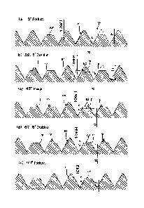
Fig. 10 shows data of looseness test conducted for a fastening structure,
to which a conventional dual-threaded screw structure is applied, being
specifically data of three test pieces in which a root diameter of a second
thread is same as an effective diameter of a first thread.
Fig. 11 shows data of looseness test performed for a fastening structure
having a looseness preventing nut as an embodiment of the dual-threaded
structure according to the present invention, being specifically data of three
test pieces in which a root diameter of a second thread is larger by 10 % than
an effective diameter of a first thread.
Fig. 12 shows data of looseness test of a fastening structure having a
looseness preventing nut as an embodiment of the dual-threaded structure
according to the present invention, being specifically data of three test
pieces
in which a root diameter of a second thread is larger by 20 % than an
effective
diameter of a first thread.
Fig. 13 shows data of looseness test of a fastening structure having a
looseness preventing nut as an embodiment of the dual-threaded structure
according to the present invention, being specifically data of three test
pieces
7
Date Recue/Date Received 2022-08-10
in which a root diameter of a second thread is larger by 30 % than an
effective
diameter of a first thread.
Fig. 14 is a three-dimensional external view showing a looseness
vibration tester with which looseness test has been conducted.
Fig. 15 is a partial enlarged view of a part A in Fig. 14.
(a) of Fig .16 is a view seen in a direction of arrow B in Fig. 15.
(b) of Fig. 16 is a view in which a head of a bolt la and a washer 20 are
removed from (a) of Fig. 16.
Fig. 17 is an explanatory view showing a relation of relative positions
of a test piece, an excitation arm and a weight attachment arm in a lengthwise
direction.
[Explanation of Preferred Embodiments]
[0017]
[Basic composition of dual-threaded screw structure 1A1
At first, problems of a conventional dual-threaded screw structure 1A
will be explained for an example of metric coarse thread. Figs. 1(a) and 1(b)
show a dual-threaded screw structure, in which Fig.1(a) is a side view and
Fig. 1(b) is a front view. The dual-threaded screw structure 1A has thread
ridges with triangular sectional shapes around the external periphery of a
shank 3A in a section including the center axis line of the shank 3A. In this
example, a first thread (Si) of a metric coarse thread (also referred to as "a
coarse thread" below) with a standard normalized pitch P (=a lead L1)
corresponding to nominal diameter is formed. Further, a second thread (S2)
with a lead L. (n*P) of determined n-times of the pitch (P) of this coarse
thread is formed on the thread ridge of the first thread. This second thread
(S2) is a thread (a thread ridge and a groove) with a triangular sectional
shape
formed continuously and spirally on the thread ridge of the first thread (51).
Also, the second thread (S2) is a one-threaded thread or multi-threaded
thread with a lead (nP) n-times of the pitch (P) of the thread, the direction
of
the spiral line of the second thread (S2) being the same twisting direction as
the first thread (Si). Precisely, the second thread (S2) is one in which
thread
number is less than the thread number of a primary multi-threaded thread
by one thread or more, and has a lead same as the primary multi-threaded
thread, in this example.
[00181
8
Date Recue/Date Received 2022-08-10
That is, strength of thread ridge of a first thread is secured by
extracting one thread or more from the primary multi-threaded thread. In
this, while the thread is one in which one thread or more is/are extracted
from
the thread number of the primary multi-threaded thread, there is a case
where the thread is not a multi-threaded, but a one-threaded thread as a
result, depending on the number of the extracted threads. Further, a lead
L1 of the first thread (Si) is smaller than a lead L. of the second thread
(S2).
The configuration and pitch P of the first thread (Si) are ones defined in the
standard concerning screws (e.g., the International Organization for
Standardization: ISO). In this embodiment, basic matters such as metric
coarse thread, etc., are employed. Here, the pitch P of the first thread (Si)
may be one different from the standard. Moreover, while the dual-threaded
screw structure 1A is shown only for the dual-threaded portion 2A and the
vicinity thereof in Figs. 1(a) and 1(b), this dual-threaded screw structure 1A
is formed as a shank, a bolt (e.g., a hexagon head bolt, a hexagon socket head
bolt, an eye bolt, a stud bolt, an anchor bolt, a set screw, a wing bolt, a U-
bolt
or a ceiling anchor bolt), etc.
[0019]
Here, while the second thread (S2) of this embodiment is preferable to
have a lead higher than determined times of a lead of the first thread (Si), a
thread with a lead of no more than four times of a lead of the first thread is
better, considering that metal material practical and common for use with
double-nut is used. The reason for this is that a nut screwed onto the second
thread (S2) needs at least more than one cycle when the lead is high, thereby
causing an axial length (height) of the nut to be long, and working becomes
difficult when the nut is fabricated with a tap, etc. Due to this, a lead no
more than of four times is preferable for the second thread (S2). As
explained above, while the first thread (Si) is of a metric coarse thread in
the
embodiment of the present invention, the first thread (Si) may be of a kind
selected from a metric thread, a Whitworth thread, a unified thread, a
trapezoidal screw thread, a pipe thread, a circular thread, a ball thread and
an angular thread, in a case of use for a fastening structure.
[0020]
[Composition of thread ridge in conventional dual-threaded screw
structure and problems thereof]
[Dual-threaded screw structure consisting of metric coarse thread and
9
Date Recue/Date Received 2022-08-10
"two-threaded thread having a three-times lead" ]
Figs. 2(a) and 2(b) are enlarged views showing a thread ridge in the
dual-threaded screw structure 1A shown in Figs. 1(a) and 1(b) as sectional
views taken in a plane including the axis line of a shank 3A for explaining a
basic composition of the dual-threaded screw structure 1A ("two-threaded
thread having a three-times lead"), in which Fig. 2(a) shows a sectional
configuration of the dual-threaded portion 2A in an "angular position of 00"
and Fig. 2(b) shows a sectional configuration of the dual-threaded portion 2A
in an "angular position of 90 ". Two kinds of threads, that is, a first thread
(Si) of a metric coarse thread and a second thread (S2) similarly of a metric
coarse thread as a standard thread ridge are formed in the dual-threaded
screw structure 1A.
[0021]
In the dual-threaded screw structure 1A, a first thread (Si) (primary
configuration thereof is shown with a one-dot chain line and a solid line)
consisting of a thread and a groove is formed on the dual-threaded portion 2A
(a solid line) of the shank 3A. This thread ridge is a standard "metric coarse
thread" defined in ISO (the International Organization for Standardization)
and a first thread (Si) having a thread with a triangular sectional shape is
formed. A nut having a common internal metric thread for a metric coarse
thread is screwed onto the first thread (Si). Further, a second thread (S2) is
formed is formed on the thread ridge of first thread (Si) as if parts of it
were
cut out (removed). This second thread (S2) in this embodiment is a special
thread in which one thread is extracted from three-threaded thread and
remaining two threads are arranged to be in an even angular phase (referred
to as a "two-threaded thread having three-times lead" below).
[0022]
The metric coarse thread as the first thread (Si) is one-threaded thread
in which the pitch P is same as the lead L1, and a groove go and thread ridge
r (a hatched portion) are formed along a spiral line h1 at a constant pitch.
The "two-threaded thread having a three-times lead" as the second thread
(S2) (the grayed portion in Figs. 2(a) and 2(b) shows a nut screwed onto the
thread portion) is a thread having a lead L3 (=313), in which two-threaded
grooves gi and g2 are formed along a spiral line h3. As the second thread (S2)
cut outs (removes) parts of thread ridges of the first thread (Si), the two
thread grooves gi and g2 are formed between the lead L3 with an equal
Date Recue/Date Received 2022-08-10
distance. This "two-threaded thread having a three-times lead" as the
second thread is arranged to provide an equal angular distance.
[00231
In Figs. 2(a) and 2(b), the first thread (Si) is a thread in which a
sectional shape of a first thread ridge r having a pitch P (=a lead L1) shown
with a contour line Si (solid line and one-dot chain line) is triangular. The
second thread (S2) of "two-threaded thread having a three-times lead" is
shown with a contour line S2 (solid line and two-dot chain line). As
explained above, grayed portions shown in Figs. 2(a) and 2(b) show a sectional
shape of a second nut screwed onto the second thread (S2). With the "two-
threaded thread having a three-times lead", a part de is formed where a
thread ridge is not formed on the thread ridge of a coarse thread between the
thread grooves gi and g2 and between the thread grooves g2 and gi, as shown
with a contour line S2 (a line parallel with the axis line appearing when the
shank is cut with a plane including the axis line of the shank). That is, a
vacant portion is formed at the part de as if it were cut out with the second
thread (S2).
[0024]
In the "angular position of 0 " in Fig. 2(a) and "angular position of 90 "
in Fig. 2(b), a low hill-like thread ridge rs of the second thread (S2) (also
being
a low hill formed by cutting out a first thread ridge r; referred to as "a
second
thread ridge re" below) with a height of thread ridge less than the thread
ridge
r of the first thread (Si) appears as if the peak of the thread ridge of the
first
thread (Si) as a basic thread ridge of a primary coarse thread were partially
cut out. In this angular position, the second thread ridge rs is formed with a
thread configuration having a contour line in which two ridges range as a
mountain range. That is, a thread ridge r of the first thread (Si) of a basic
thread ridge (triangular) of a coarse thread as seen from the first thread
(Si)
is cut out by forming the second thread (S2), so that height of the thread
ridge
r of the first thread becomes lower. Allowable shearing stress or allowable
contact face pressure of the thread ridge rs in this part becomes lower than
that of the basic thread ridge (primary triangular thread ridge) of the first
thread (Si). Further, there exists parts where thread ridge is not formed on
the first thread (Si) in any angular position at all with the dual-threaded
screw structure 1A shown in Figs. 2(a) and 2(b) (for example, in angular
position of 0 , angular position of 180 , etc. ), so that parts where primary
11
Date Recue/Date Received 2022-08-10
triangular basic thread ridge of a coarse thread ridge is not formed appear.
[00251
Fig. 3 shows sectional views of sectional configuration of thread ridge
for particular angular positions in the dual-threaded portion 2A on the shank
3A shown in Fig. 2. That is, (a) to (e) of Fig. 3 are sectional views showing
sectional configuration in angular positions for every 22.5 around the axis
line of the dual-threaded portion 2A shown in Figs. 1(a) and 1(b). With this
dual-threaded screw structure 1A, sectional configuration of same
combination appears repeatedly for a determined period as shown in (a) to (e)
of Fig. 3. For example, with the "two-threaded thread having a three-times
lead" shown in Figs. 2(a) and 2(b), a same configuration appears repeatedly
with two leads combined for a period three times of a pitch of the coarse
thread. As shown in (a) and (e) of Fig. 3 for angular positions of 0 and 90
respectively, two ranging hill-like second thread ridges rs lower than the
basic
thread ridge r of the first thread (Si) is formed so as to have an outer
diameter
same as an effective diameter d of the first thread (Si). Further, as shown
in (b), (c) and (d) of Fig. 3, hill-like second thread ridges r1-r6 with
various
heights lower than the basic thread ridge r of the first thread (Si) are
formed
respectively. With a conventional dual-threaded screw structure shown in
Fig. 4, grooves between the second thread ridges r1-r6 of the dual-threaded
screw structure shown in Fig. 3 are filled so as to have same diameter as the
effective diameter (d) of the first thread.
[00261
With this conventional dual-threaded screw structure 1A, in a case
where double nuts for preventing looseness is used by reverse method in a
fastening structure 80 as shown in Figs. 8(a) and 8(b), a second nut 83 (a nut
for preventing looseness) of an internal thread is screwed onto the second
thread (S2) lightly at first (see Figs. 8(a) and 8(b)). Next, a first nut 82
of an
internal thread (a nut for fastening) is screwed onto the first thread (Si)
(metric coarse thread) with management of fastening performed by a torque
controlling method, etc. At this time, the second nut 83 is rotated further
with rotation of the first nut 82 to fasten the members to be fastened 84 with
a preset torque. After this fastening, it is usually necessary to impart
return
locking force by rotating the second nut 83 adversely in order to lock both
nuts securely.
[00271
12
Date Recue/Date Received 2022-08-10
That is, axial force using a dual-threaded screw structure 81 fastened
with double nuts as shown in Figs. 8(a) and 8(b) is generated by the first nut
82 screwed onto the first thread (Si). Along with this, the second nut 83 as
a nut for preventing looseness is unscrewed to generate locking force between
the second nut 83 and the first nut 82, thus providing effect of preventing
looseness. Lead angles of the two nuts are different each other, which brings
an effect of preventing looseness. With this fastening structure 80 provided
with a nut for preventing looseness, a high axial force can be imparted to the
hexagon head bolt 81 by fastening the members to be fastened 84 with the
first nut 82 for the first thread (Si) screwed onto the first thread (Si) of
the
dual-threaded portion 2A. As a result, fastened situation can be held even
when external force is applied to the members to be fastened 84 in the axial
direction.
[00281
However, with a conventional dual-threaded screw structure 1A as
shown in Figs. 2(a), 2(b) or Fig. 3, hill-like second thread ridges r1-r6 with
various heights lower than the basic thread ridge r of the first thread (Si)
are
formed respectively. Consequently, when fastening is performed by rotating
the first nut 82 with a fastening torque higher than a level exceeding an
allowable tensile stress of the bolt 81, shearing stress and contact face
pressure are applied to the thread ridge of the hexagon head bolt 81 in an
axial direction with an reaction force from the members to be fastened 84. If
the shearing stress and contact face pressure exceed the allowable shear
fracture stress and allowable contact face pressure of the hill-like second
thread ridges r1-r6 respectively, there is a fear that shear fracture or
plastic
deformation occurs first in weak parts. Thus, in the Patent Document 1
explained above, a root diameter between the thread ridges of the hill-like
second thread ridges rs, r1-r6 is made to be same as or less than an effective
diameter d of the first thread (Si) (a structure in which grooves between the
hill-like thread ridges are filled) as shown in Fig. 4, so as to prevent shear
fracture or plastic deformation of the hill-like second thread ridges rs, r1-
r6.
Further, in the Patent Document 1 explained above, an inner diameter (D) of
the internal thread of the second nut 83 as a nut for preventing looseness is
made to be same as an effective diameter d of the first thread (Si) as shown
in Fig. 8(b). Fig. 8 (b) shows configuration in an angular position of 450 as
shown in (c) of Fig. 4.
13
Date Recue/Date Received 2022-08-10
[0029]
[Looseness test of nuts with a looseness vibration tester]
After a root diameter between the thread ridges of the hill-like second
thread ridges rs, r1-r6 has been made to be same as or less than an effective
diameter d of the first thread (Si) and fastening of this has been performed
in a method by double nuts, test of this fastened structure was conducted with
a looseness vibration tester. With the test, it was found that the dual-thread
screw structure has not most effective configuration. Figs. 14 to 17 show an
external view of a looseness vibration tester and detailed portion thereof
respectively. Looseness test of a fastened structure was conducted in which
a conventional dual-threaded screw structure is fastened in a method by
double nuts. Fig. 10 is data showing a result of test of the fastened
structure
of the dual-threaded screw structure, in which root diameter of the second
thread is of an effective diameter of the first thread.
[0030]
This vibration test, shown as the table in Fig. 10, was conducted in a
manner that looseness test was repeated ten times for each of three test
pieces
1 to 3 (not shown) respectively. Each of the test pieces 1 to 3 is a dual-
threaded screw structure with a nominal diameter of 12 mm made of a
material SCM. A first nut made of SCM with a length of 10 mm and a second
nut made of SCM with a length of 10 mm were used. As a test method, after
fastening has been performed first with a fastening torque of 42 Nm by a first
nut, setting a vibration frequency to be 35 Hz and a test time for 1 time to
be
29 seconds, initial axial force after fastening and residual axial force after
test
of 1 time were measured. Looseness test was conducted repeatedly 10 times
in a similar manner. "initial axial force (kN)" in Fig. 10 is an axial force
generated in a bolt when fastening has been performed with a fastening
torque of 42 Nm by a nut of coarse thread as a first nut. "residual axial
force
(kN)" is an axial force remaining in a bolt after looseness test. "residual
axial
force (%)" is a ratio of a residual axial force after test. As shown in Fig.
10,
it was found that initial axial force is low to be 18.4 kN (test piece 3) at
maximum, initial axial force varies to a large extent from 6.4 kN to 18.4 kN
and minimum of residual axial force is lowered to be 1 %, thus looseness is
generated.
[00311
[Explanation of a looseness vibration tester]
14
Date Recue/Date Received 2022-08-10
The above explained looseness vibration tester, with which looseness
test for the present invention was conducted, is a tester proposed by the
present inventors (Japan Patent No.6,383,121) and this is not a known
technology at the time of filing the present application, so summary of this
will be explained below. Fig. 14 is a three-dimensional external view
showing a looseness vibration tester 50 with which the above looseness test
was conducted. Fig. 15 is a partial enlarged view of a part A in Fig. 14,
(a) of Fig .16 is a view seen in a direction of arrow B in Fig. 15, (b) of
Fig. 16
is a view in which a head of a bolt la and a washer 20 are removed from (b)
of Fig. 16. Fig. 17 is an explanatory view showing a relation of relative
positions of a test piece, an excitation arm and a weight attachment arm along
a lengthwise direction.
[00321
This looseness vibration tester 50 is composed so as to load a bolt and
nut 1 for test (referred to as a "fastening screw structure" below) with
vibration perpendicular to axis, vibration around axis (vibration with angular
acceleration) and vibration along axis. In contrast, it is possible to load a
bolt and nut for test only with vibration perpendicular to axis in a case of
NAS
impact vibration tester or Junker vibration tester conventionally used in
common. Further, the looseness vibration tester 50 is composed so as to
conduct real time measurement of variation process of axial force (lowering
axial force) in a bolt of the fastening screw structure 1 when longitudinal
vibration (frequency of vibration) is imparted to an excitation arm 2 of the
two arms (an excitation arm 2, a weight attachment arm 3) fastened with the
fastening screw structure 1.
[00331
With the composition of this looseness vibration tester 50, two layered
plate shaped excitation arm 2 and weight attachment arm 3, as members to
be fastened, are fixed with a fastening screw structure 1 as a test piece.
Then, excitation arm 2 and weight attachment arm 3, as members to be
fastened, are driven mechanically to conduct looseness test of the fastening
screw structure 1. The looseness vibration tester 50 comprises a excitation
arm 2 for loading the fastening screw structure 1 with determined vibration
and a weight attachment arm 3 as well as a driving mechanism for driving
the excitation arm 2 and weight attachment arm 3 to be vibrated.
[00341
Date Recue/Date Received 2022-08-10
In general, a main portion of this looseness vibration tester comprises
a weight 4 attached to the weight attachment arm 3, an activating shaft 5
connected to the excitation arm 2 for reciprocating motion (single vibration)
in a determined stroke, a cylinder 6 for supporting the activating shaft 5
longitudinally and causing it to slide longitudinally, etc. A crank mechanism
causes the activating shaft 5 to reciprocate. The crank mechanism
comprises a crank 7 converting a rotating motion into a reciprocating motion,
a crank shaft 8 as a rotating shaft of the crank 7, a motor 9 generating
rotation power for causing the activating shaft 5 to reciprocate, pulley 10
transmitting the rotation power of the motor 9 to the crank shaft 8, etc. One
end of the excitation arm 2 is connected to an upper end of the activating
shaft
with a connecting shaft 11. The weight attachment arm 3 swings (in a
seesaw motion) around a shaft for swinging 12. The shaft for swinging 12 is
supported by a main body with a bearing supporting member 13 for rotatable
supporting. The looseness vibration tester 50 is composed so as to provide,
beside these for driving mechanism, a computer PC (not shown) for
processing-displaying data relating to axial force of a bolt of a fastening
screw
structure 1, a torque sensor (not shown) for measuring fastening torque to the
fastening screw structure 1, etc.
[00351
As shown in Fig.15, the fastening screw structure 1 comprises a bolt la
and two nuts lb, lb screwed onto the bolt la (so called double nuts).
Between the bolt la and a nut lb, the excitation arm 2 and the weight
attachment arm 3 as members to be fastened, washers 20 for causing axial
force of a bolt (a fastening force) by the fastening screw structure 1 to be
applied in a wide area (for equalization of contact) and a load cell lc for
measuring axial force of a bolt (fastening force) of the fastening screw
structure 1 are provided. The excitation arm 2 and the weight attachment
arm 3 are fastened in a parallel joined state by the fastening screw structure
1 via the washer 20, 20 with a decided fastening torque. A concave portion
2a is formed on the excitation arm 2 in a site for the bolt la to be attached
thereto. Similarly, a concave portion 3a is formed on the weight attachment
arm 3 in a site for the nut lb to be attached thereto.
[00361
Further, rotatable swing restraining pins 30, 30 passing through the
excitation arm 2 and the weight attachment arm 3 are provided on both sides
16
Date Recue/Date Received 2022-08-10
of the fastening screw structure 1 respectively. While details are explained
later referring to Fig. 16, bending angle of the excitation arm 2 and the
weight
attachment arm 3 is restrained below a decided angle by the swing
restraining pins 30, 30. As shown in (a) of Fig. 16, both sides of the washers
20 are cut off in straight lines and the washers have a shape in which
circular
portions 20a and straight line portions 20b are connected alternately each
other. Further, a gap dO (referred to as a "washer gap dO" below) is formed
between the straight line portion 20b and the concave portion 2a. Material
of the washer is, for example, S45C (carbon steel material) with HRC
(hardness) of 45 to 50, in which surface treatment is applied to form tri-iron
tetroxide film on the surface.
[00371
Further, as shown in (b) of Fig. 16, through-holes for bolt 2b, 3b are
formed in the respective concave portions 2a, 3a of the excitation arm 2 and
the weight attachment arm 3. There is a gap (allowance) dl (referred to as
"bolt allowance dl" below) between the through-hole for bolt 2b, 3b and the
bolt la. Similarly,
through-holes for pin 2c, 3c allowing the swing
restraining pins 30, 30 to pass through are formed on both sides of the
respective concave portions 2a, 3a. There is a gap (allowance) d2 (referred
to as "pin allowance d2" below) between the through-holes for pin 2c, 3c and
the swing restraining pin 30. Other than these, there are allowance between
the activating shaft 5 and the connecting shaft 11, allowance between the
shaft for swinging 12 and the bearing supporting member 13, allowance
between the washer 20 and the bolt la, etc. As convenience for following
explanation, it is thought that bolt allowance dl -. pin allowance d2 -.
washer
gap dO, and mechanical allowance other than washer gap dO, bolt allowance
dl and pin allowance d2 will not be considered.
[00381
Consequently, when the activating shaft 5 reciprocates up and down
(moves in single vibration), the excitation arm 2 can make shifting leftwards-
rightwards relative to the fastening screw structure 1 by a washer gap dO in
a lengthwise direction of itself as well as swing up and down by a pin
allowance d2 around the connecting shaft 11 as a fulcrum. On the other
hand, although the weight attachment arm 3 cannot make shifting relative
to the fastening screw structure 1 in a lengthwise direction of itself, it can
17
Date Recue/Date Received 2022-08-10
swing up and down by a pin allowance d2 around the shaft for swinging 12 as
a fulcrum. The fastening screw structure 1 can make shifting leftwards-
rightwards by a washer gap dO relative to the weight attachment arm 3 in a
lengthwise direction as well as make relative shifting up and down by a bolt
allowance dl. Due to this, the excitation arm 2 can make shifting relative to
the weight attachment arm 3 by 2d0 at maximum in a lengthwise direction
of itself.
[00391
Further, the weight attachment arm 3 is usually forced to be rotated in
a clockwise direction as shown in Fig. 16 by the weight 4. Consequently,
when the activating shaft 5 reverses direction of movement, swinging of the
excitation arm 2 or swinging of the weight attachment arm 3 is reversed or
stopped forcibly. In this case, the fastening screw structure 1 is loaded with
an impact force in a direction perpendicular to axis (referred to "impact
force
perpendicular to axis" below) via the excitation arm 2 or with an impact
moment in a direction around axis via the weight attachment arm 3.
Furthermore, in a case where there is a long distance from the shaft for
swinging 12 to the weight 4, the fastening screw structure 1 is loaded with an
impact force in an axial direction via the weight attachment arm 3 when the
activating shaft 5 reverses direction of movement.
[00401
The activating shaft 5 (connecting shaft 11) makes reciprocating motion
in a longitudinal (vertical) direction by a decided stroke (e.g., 11mm). The
excitation arm 2, working together with this, makes relative shifting to the
fastening screw structure 1 in a lengthwise direction of itself leftwards-
rightwards in Fig. 16, along with swinging up and down around the
connecting shaft 11 as a fulcrum. On the other hand, the weight attachment
arm 3, working together with reciprocating motion of the activating shaft 5,
swings (in a seesaw motion) around the shaft for swinging 12 (a fixed point)
as a fulcrum. Stroke of the activating shaft 5 is set so that the excitation
arm 2 makes a maximum relative shifting in a lengthwise direction of itself
relative to the weight attachment arm 3 when the activating shaft 5 attains
a lowermost point. In this case, the fastening screw structure 1 is loaded
with an impact force perpendicular to axis via the excitation arm 2 and also
with an impact moment in a direction around axis by the weight 4 via the
weight attachment arm 3. In this, a state where the connecting shaft 11 and
18
Date Recue/Date Received 2022-08-10
the shaft for swinging 12 are in a same height will be referred to as "a
neutral
state" below.
[0041]
In a similar manner, when a sum (=L1+L2) of a distance Li between
the bolt la and the connecting shaft 11 and a distance L2 between the bolt la
and the shaft for swinging 12 is a maximum, the fastening screw structure 1
(bolt la) is loaded with an impact force perpendicular to axis via the
excitation
arm 2. At the same time, the fastening screw structure 1 (bolt la) is loaded
with an impact moment in a direction around axis via the weight attachment
arm 3. In this, it will be referred to as "vibration perpendicular to axis"
below to be loaded repeatedly with an impact force perpendicular to axis via
the excitation arm 2. Further, it will be referred to as "vibration around
axis"
or "vibration of angular acceleration around axis" below to be loaded
repeatedly with an impact moment in a direction around axis by the weight
4 via the weight attachment arm 3. Furthermore, a sum of a distance Li
between the bolt la and the connecting shaft 11 and a distance L2 between
the bolt la and the shaft for winging 12 in a neutral state is to be LO.
[0042]
Returning to Fig. 14 again, a three-phase AC motor, for example, can
be used as the motor 9. In this case, rotation frequency of the motor 9 is
controlled by an inverter. Fig. 17 is an explanatory view showing a relation
of relative positions of the fastening screw structure 1, the excitation arm 2
and the weight attachment arm 3 in a lengthwise direction. (a) of Fig. 17
shows these relative positions in a neutral state. (b) of Fig. 17 shows these
relative positions when the excitation arm 2 has made a relative shifting by
a washer gap dO relative to the fastening screw structure 1 in a lengthwise
direction. (c) of Fig. 17 shows these relative positions when the excitation
arm 2 has made a relative shifting by 2d0 in a lengthwise direction.
[00431
As shown in (a) of Fig. 17, a washer gap dO is provided between each of
the concave portions 2a, 3a and each of the washers 20, 20 respectively. On
the other hand, a bolt allowance dl is provided between the bolt la and the
excitation arm 2 or the weight attachment arm 3 respectively. Further, a pin
gap d2 is provided between the swing restraining pin 30 and the excitation
arm 2 or the weight attachment arm 3 respectively.
[0044]
19
Date Recue/Date Received 2022-08-10
As shown in (b) of Fig. 17, when the activating shaft 5 (shown in Fig.
16) begins moving downwards, the excitation arm 2 makes relative shifting
leftwards as shown relative to the fastening screw structure 1 in a lengthwise
direction. In this case, washer gap dO -. bolt allowance dl, pin gap d2, so
that
the washer on the bolt head side abuts on the inner wall of the concave
portion
2a of the excitation arm 2. As a result, the washer 20 is pushed by inner wall
of the concave portion 2a of the excitation arm 2, so that the excitation arm
2
and the fastening screw structure 1 integrally begins relative shifting
leftwards as shown in (b) of Fig. 17 relative to the weight attachment arm 3.
In this case, distance between the bolt and the connecting shaft becomes L1+
dO.
[00451
As shown in (c) of Fig. 17, the excitation arm 2 and the fastening screw
structure 1 integrally makes relative shifting leftwards as shown relative to
the weight attachment arm 3, so that the washer nut 20 on the nut 1 side
abuts on the inner wall of the concave portion 3a. Then, when the activating
shaft 5 (in Fig. 16) attains a lowermost point, relative shifting of the
excitation
arm 2 and the weight attachment arm 3 is forcibly stopped. That is,
momentum of the excitation arm 2 is forced to be zero and, along with this,
angular momentum of the weight attachment arm 3 is forced to be zero, in a
state where the weight attachment arm 3 is forced with the weight 4. As a
result, the fastening screw arm 1 (bolt la) is loaded with an impact force
perpendicular to axis via the excitation arm 2 and at the same time the
fastening screw structure 1 (bolt la) is loaded with an impact moment around
axis by the weight 4 via the weight attachment arm 3. In this case, distance
between the bolt la and the shaft for swinging 12 becomes L2+d0 in a state
where distance between the bolt la and the connecting shaft 11 is maintained
to be L1+d0.
[00461
[Result of screw looseness test]
Returning to the above explained results of the vibration test of Fig. 10,
what causes looseness to occur in a fastening structure with a looseness
preventing nut disclosed in Patent Document 1 is considered as follows, as
shown in a result of vibration test. That is, even if a root diameter between
the ridges of hill-like second thread ridges rs, rsi ¨ rs6 is made to be same
as
Date Recue/Date Received 2022-08-10
an effective diameter d of a first thread (Si) as shown in Fig. 4, rigidity of
the
hill-like second thread ridges rs, rsi ¨ rs6 with an enlarged root diameter
between the ridges is lower than rigidity of a first thread ridge r as a basic
thread ridge of a first thread (Si). Consequently, it is considered that, if
looseness vibration test of a screw as explained above is conducted for a
fastening structure 80 as shown in Figs. 8(a) and 8(b) in which a first nut 82
is fastened onto a hexagon head bolt 81 with a high fastening torque, the hill-
like second thread ridges rs, rsi ¨ rs6 undergo elastic deformation to lower
an
axial force.
[0047]
[ Explanation of the dual-threaded screw structure according to embodiments
of the present invention]
As explained above, in a case where a fastening structure with double
nuts having conventional constitution is loaded with severe loose load,
possibility of lowering axial force cannot be denied. From this, with dual-
threaded screw structures 1A according to embodiments of the present
invention, a root diameter between the ridges of hill-like second thread
ridges
rs, rsi ¨ rs6 is formed to be larger than an effective diameter d of a first
thread
(Si) as shown in Figs. 5 to 7. Figs. 9(a) and 9(b) show an example in which
a dual-threaded screw structure according to an embodiment of the present
invention is applied to a fastening structure 800 with a looseness preventing
nut, in which Fig. 9(a) is a partial sectional view and Fig. 9(b) is a
sectional
view showing the dual-threaded structure engaged with nuts. As shown in
Fig. 9(b), also the inner diameter (D1) of the internal thread of a second nut
830 as a looseness preventing nut is formed to be larger than the effective
diameter d of the first thread (Si).
[0048]
Fig. 5 shows an example in which a root diameter between the ridges
of hill-like second thread ridges rs, rsi ¨ rs6 is formed to be larger by 10%
than
an effective diameter d of a first thread (Si). In this case, also for the
inner
diameter of the internal thread of a second nut 830 as a looseness preventing
nut, a root diameter of a second thread is formed to be larger than the
effective
diameter d of the first thread (Si) by 10%. Here, a root diameter of a second
thread formed to be larger by 10% is such that, taking the height of a ridge
of
the first thread to be H (a height by supposing an isosceles triangle; see (a)
of
Fig. 5), the root diameter of the second thread is raised by h for a radius
(2h
21
Date Recue/Date Received 2022-08-10
for a diameter) as h=Hx10%. A root diameter of a second thread formed to
be larger by 20% or 30% than the effective diameter is taken so for ones
obtained by calculating in a similar manner.
[00491
Further, Fig. 6 shows an example in which a root diameter between the
ridges of hill-like second thread ridges rs, rsi ¨ rs6 is formed to be larger
by
20% of the height H of the ridge (a height by supposing an isosceles triangle)
than an effective diameter d of a first thread (Si). In this case, also the
inner
diameter (D1) of the internal thread of the second nut 830 as a looseness
preventing nut is formed to be larger by 20% of the height of ridge than the
effective diameter d of the first thread (Si). Further, Fig. 7 shows an
example in which a root diameter between the ridges of hill-like second thread
ridges rs, rsi ¨ rs6 is formed to be larger by 30% than an effective diameter
d
of a first thread (Si). In this case, also the inner diameter (D1) of the
internal
thread of the second nut 830 as a looseness preventing nut is formed to be
larger by 30% of the height of ridge than the effective diameter d of the
first
thread (Si). Figs. 9(a) and 9(b) show a fastening structure 800 of a hexagon
head bolt 810 in which a root diameter between the ridges of hill-like second
thread ridges rs, rsi ¨ rs6 is formed to be larger by 10% or 20% of the height
H
of the ridge than an effective diameter d of a first thread (Si) with
looseness
preventing nuts used as double nuts. A second nut 830 (a looseness
preventing nut) having an internal thread is screwed onto the second thread
(S2) at first.
[00501
In the next, a first nut 820 (a fastening nut) having an internal thread
820 is screwed onto the first thread (Si) (a metric coarse thread) with a
decided fastening torque. At this time, the second nut 830 is rotated further
with rotation of the first nut 820 to be fastened onto a member to be fastened
840. The second nut 830 is not unfastened in principle in this embodiment.
The inner diameter of the second nut 830 is formed to be larger by 10% or
20% of the height H of the ridge than an effective diameter d of the first
thread
(Si). The second nut 830 has a flange 831 with a large diameter formed on
the face abutting on the member to be fastened 840, thus being a nut having
a flange in this embodiment. Locking force between the first nut 820 and
the second nut 830 can be raised by forming a flange 831, thus lowering
possibility of looseness. Fig. 9(b) shows a section of (c) of Fig. 6 at an
angular
22
Date Recue/Date Received 2022-08-10
position of 45 .
[0051]
As shown in Fig. 9(b), the inner diameter (D1) of the internal thread of
the second nut 830 is formed to be larger the effective diameter d of the
first
thread (Si), so that straight line portions 832 in a sectional shape, that is,
a
spiral circular bore are formed in the inner diameter (D1) of the internal
thread of the second nut 830. Further, a plurality of small ridge rp having
height variable corresponding to angular positions (see Fig. 5, Fig. 6 and
Fig.
9(b)) are formed on the peak of the second thread (S2). As a result, the
internal thread of the second nut 830 is engaged with the small ridge rp on
the top of the second thread (S2), so that contact area of the internal thread
of the second nut 830 with the second thread (S2) decreases, thus raising
contact pressure per unit area of the thread face. However, as fastening
force is shared by the first nut 820 in the dual-threaded screw structure of
the present invention, there is no problem. Function of the second nut 830
does not consist in fastening force, but the nut is one having function
preventing looseness of the first nut 820. Consequently, shear breaking of
the second nut 830 and small ridges never occurs.
[0052]
[Looseness test of a dual-threaded screw structure]
Looseness tests of the dual-threaded screw structure according to
embodiments of the present invention has been conducted with the above
explained looseness vibration tester 50 and data have been obtained as shown
in Figs. 11 to 13. These data have been obtained by conducting tests ten
times for each of test pieces 1 to 3, in a similar manner as the result of
vibration test shown in Fig. 10. Further, also condition of test is similar to
the vibration test shown in Fig. 10, with a vibration frequency of 35 Hz, a
test
time of 29 seconds and a fastening torque of the first nut of 42 Nm.
Furthermore, chromium molybdenum steel material (SCM material) used as
a standardized material of bolts and nuts is employed for these fastening
structure, for which tests have been conducted. Data shown in Fig. 11 is one
obtained for a dual-threaded screw structure in which a root diameter
between the ridges of second thread ridges is formed to be larger by 10% of
the height H of the ridge (when a basic thread of the second thread is taken
as an isosceles triangle) than an effective diameter d of the first thread
(Si).
Here, the first thread is a metric coarse thread with a nominal diameter of 12
23
Date Recue/Date Received 2022-08-10
mm and the second thread is a two-threaded coarse thread having a three-
times lead and has a shape of the ridge same as a metric coarse thread (in a
sectional plane perpendicular to the spiral line and the tangent line.
[00531
The looseness test was commenced after the first nut was fastened with
a torque of 42 Nm before the test (axial force at this time is taken as 100%).
Data shown in Fig. 11 was for a dual-threaded screw structure in which a root
diameter between the ridges of second thread ridges is formed to be larger by
10% of the height H of the ridge than an effective diameter d of a first
thread
(Si). With the data, axial force was high with a maximum of 19.8 KN for ten
times of looseness tests, and axial force was in a range of 10.7KN to 19.8 KN.
In the data, variation was smaller than the conventional one shown in Fig.
and residual axial force was high to be 69 to 89%, so that it was found
looseness did not occur compared with the prior arts explained above. The
data shown in Fig. 12 is similarly for a dual-threaded screw structure in
which height of a root diameter of the second thread is formed to be larger by
20% than an effective diameter d of a first thread (Si). In Fig. 12, axial
force
was high with a maximum of 18.8 KN, and axial fore was in a range of 10.4KN
to 18.8 KN with variation smaller than the conventional one shown in Fig. 10
and residual axial force was high to be 68 to 92%, so that it was found
looseness did not occur.
[00541
Similarly, Fig. 13 shows data for a dual-threaded screw structure in
which a root diameter of the second thread ridges is formed to be larger by
30% than an effective diameter d of a first thread (Si). With the data shown
in Fig. 13, axial force became zero in the sixth test for the test piece 1,
hill-
like ridges of the second thread underwent plastic deformation and axial force
became zero with repeated loads of six times. This seems to be caused as
follows. That is, the larger than the effective diameter d of the first thread
(Si) the root diameter between ridges of hill-like thread ridges of the second
thread is formed to be, the nearer to primary rigidity of the first thread
ridge
r of the first thread (Si) comes rigidity of the first thread (Si) with root
diameter between the ridges made lager, so that strength between the first
nut 820 and the first thread (Si), that is, shearing stress in the hill-like
ridges
is within an allowable range or elastic deformation of the threads is within
an allowable range, thus never creating a problem. However, as shown for
24
Date Recue/Date Received 2022-08-10
angular positions of 22.5 and 67.5 in Fig. 7, only ridges rq still smaller
than
the small ridges rp as shown in Figs. 5 and 6 are formed in a large number at
the top of ridge of the second thread (S2) with root diameter formed to be
larger by 30%.
[0055]
As a result, only small ridges rq at the top of ridge of the second thread
(S2) are engaged with the second nut, so that contact area of the internal
thread of the second nut with the second thread (S2) decreases. This is
caused by occurrence of shear breaking or plastic deformation of the small
ridges rq when the dual-threaded screw structure under looseness test is
loaded with high loads (axial force or fastening torque) in this state.
Phenomena of such breaking or plastic deformation was recognized also by
observing test pieces. The results of the tests explained above exhibits that
while making root diameter of thread ridges of the second thread larger is
effective for holding axial force when the a shank of screw or a nut is loaded
with load of torque, it is not effective when the load of torque exceeds a
determined value.
[0056]
[Principle of fastening with double nuts for a dual-threaded screw structure]
Principle of fastening with double nuts for a dual-threaded screw
structure according to the present invention will be explained, taking a
fastening structure with a looseness preventing nut fastened by double
locking nuts as shown in Fig. 9(c) as an example. A toque T necessary for
rotating a second nut 830 under an axial force W is generally given by the
following equation (1).
T=W(d2/2)tan(a+p) (1)
Here, W: axial force of the dual-threaded screw structure 810, p':
friction angle of a contact face with which the second thread contacts with
the
second nut, d2: effective diameter of thread face with which the second thread
contacts with the second nut and a: lead angle of the second thread.
In this, the effective diameter d2 of the ridge of the second thread (ridge
with which the second thread 830 contacts) is taken as a height averaged for
1/2 of the height of ridge as the height varies depending on angular position.
Further, when root diameter of the second thread is same as inner diameter
D1 of the second nut, the effective diameter d2 is of a value obtained by
dividing a sum of outer diameter d3 of the ridge and inner diameter D1 of the
Date Recue/Date Received 2022-08-10
second thread by 2 (see Fig. 9(c)).
A torque T1 after the seat 831a of the second nut 830 has contacted
with the member to be fastened 840 is generally given by the following
equation (2).
T1=W[(d2/2) = tan(a+O-Fr2. tanpi (2)
Here, r2: averaged radius of the seat 831a with which the second nut
830 contacts with the member to be fastened 840, a: lead angle of the second
thread and p: friction angle of the seat 831a with friction coefficient p.
[00571
On the other hand, when the fastening structure 800 is fastened, the
second nut 830 is fastened, being driven to be rotated indirectly by rotating
the first nut 820. At this time, the second nut 830 is rotated by friction
force
of the seat 830a with which the first nut 820 contacts with the second nut 830
each other. Torque Ti' with which the second nut 830 is driven to be rotated
by this rotation of the first nut 820 is given by the following equation (3),
in a
case where friction coefficient p is same as one of the seat 831a of the
second
nut 830.
Ti'=tanp = W = ri (3)
Here, ri: averaged radius of the seat 830a with which the first nut 820
contacts with the second nut 830 each other and p: friction angle of the seat
831a with friction coefficient p (p= tanp).
[00581
In this, in order to obtain a locking force between the first nut 820 and
the second nut 830 by rotation of the first nut 820 alone with a determined
fastening torque, operation must be done as follows. It is required that the
second nut 830 is rotated by rotating the first nut 820 at first, then the
seat
831a of the flange 831 of the second nut 830 contacts with the member to be
fastened 840 and the rotation of the second nut 830 is ceased by friction
force
of the seat 831a in the next, after which the first nut 820 is fastened with a
determined torque, thus creating mutual locking force for preventing
looseness of this fastening structure 800.
In order that rotation of the second nut 830 is ceased after it has
contacted with the member to be fastened 840, the following condition is
necessary to be established.
26
Date Recue/Date Received 2022-08-10
T1 > T1'
T1=W[(d2/2) = tan(a+O-Fr2. tanp] > Ti' = tanp = W = ri .. (4)
Therfore,
Rd2/2) = tan(a+O-Fr2. tanp] > tanp = ri (5)
With this condition established and only by fastening the first nut 820
with a torque of such a determined value that the ridges of the second thread
does not undergo plastic deformation with shear stress or contact pressure as
explained later, it is not necessary with the present invention to unscrew the
second nut 830 and impart locking force, but required locking force can be
obtained, considering from the results of looseness vibration tests explained
above.
[0059]
[Observation of looseness of double nuts in use of a dual-threaded screw
structure]
With repeated rotation torque by the looseness vibration tester 50
explained above, mechanism creating looseness of a screw is considered as
follows. Condition for the ridges shown in Fig. 7, etc., in the fastening
structure 800 shown in Fig. 9(a) to undergo plastic deformation will be
explained. As shown in Fig. 17, etc., as external forces causing looseness to
occur in a fastening screw structure 1 in tests with a vibration tester 50 of
screw looseness, repeated swinging motion of an excitation arm 2 rotates a
bolt la via its contact seat, or repeated swinging motion of a weight
attachment arm 3 rotates a seat of the nut lb to create looseness in the
fastening screw structure 1. Further, from a result by observing the test
pieces, it was observed that ridges rq underwent plastic deformation when
looseness occurred.
[0060]
[Breaking or deformation of thread ridges by shear force]
(1) Torque from a second nut 830
From reviewing of driving to loosen with external force in a vibration
tester 50 of screw looseness and of results of tests, reason for looseness of
the
fastening structure 800 with a looseness preventing nut will be explained
referring to Fig. 9(c). etc. Considering from a constitution for fastening in
27
Date Recue/Date Received 2022-08-10
the fastening structure 800, looseness in the fastening structure 800 is
caused
by a second nut 830 or a dual-threaded screw structure 810 driving a member
to be fastened 840 to be rotated. In this, when the fastening structure 800
is fastened with an axial force W and the second nut 830 with a high lead is
rotated from the side of the member to be fastened 840, the following torque
T2 is created via a seat 831a.
T2=W = tanp = r2 (6)
Here, r2: averaged radius of the seat 831a with which the second nut
830 contacts with the member to be fastened 840, and p: friction angle of the
seat 831a (p= tanp). When the torque T2 is created by the external force, the
following axial force W1 is created. From the above explained equation (1),
W1=T2/(d2/2) = tan(a+0 .......................... (7)
Here, p': friction angle of a contact face with which the second nut with
friction coefficient p contacts with the ridge, d2: effective diameter of
thread
face with which the second thread contacts with the second nut and a: lead
angle of the second thread.
[00611
(2) Torque of loosening from the side of a head portion 811 of a dual-threaded
screw structure 810
In the above explained looseness vibration tests, the external force on
the ridges rp of the fastening structure 800 is not only a torque from the
second nut 830, but the member to be fastened 840 is rotated from the side of
a seat 811a of a head portion 811 Of the dual-threaded screw structure 810
with a torque T3 rotating the member 840 in a fastening direction or in a
loosening direction (the second nut 830 side). This torque T3 creates an axial
force W2. In a similar manner as the above equation (6),
T3=W = tanp = r3 (8)
Here, r3: averaged radius of the seat 811a with which the head portion
811 of the dual-threaded screw structure 810 contacts with the member to be
fastened 840 and p: friction angle of the seat 811a (p= tanp).
With this torque T3, the following axial force W2 is created.
W2=T3/(d2/2)=tan(a+0 ............................ (9)
28
Date Recue/Date Received 2022-08-10
Here, d2: effective diameter of thread face with which the second thread
contacts with the second nut and p': friction angle of a contact face of
ridges
with which the second nut contacts, in a case of friction coefficient p.
[00621
(3) Shear stress created in ridges of the second thread
On the other hand, condition for a ridge of the rotated bolt la (a thread
ridge with which the second nut contacts) to undergo shear breaking is
considered as follows.
As flank angle is 600 for a metric coarse thread, a mean shearing length per
a ridge AB becomes as follows from an equation for obtaining a base side of
an isosceles triangle (see the enlarged view of A in Fig. 9(c)).
AB=(d3-D1) tan(13/2) (10)
Here, d3: outer diameter of ridge, D1: inner diameter of the second nut
830 and 13: flank angle of thread ridge.
In this, as a mean shearing length AB varies depending on angular
position, a mean value may be used for calculation.
Then, taking an allowable axial load when a ridge of the dual-threaded
screw structure 810 undergoes shear breaking or plastic deformation as WB,
the following equation is obtained, as "TrDiABz" is an area where the ridge is
loaded with a shear load.
WB =TED ABTE ......................................... (11)
Here, 1: allowable shear breaking stress of a material of the dual-
threaded screw structure 810, D1: inner diameter of the nut 830 and z:
number of ridges taken as ones having ability of being loaded. In this, as z
can be obtained by calculation when a length L of the second nut is given,
also
allowable axial load WB can be calculated.
[00631
[Reason for looseness in fastening structure with dual-threaded screw
structure fastened with double nuts]
In the above explained looseness tests, the head portion 811 of the dual-
threaded screw structure 810 shown in Fig. 9(c) abuts on the member to be
fastened 840 via the seat 811a and the second nut 830 having a high lead is
driven to be rotated in a direction of fastening or loosening the member to be
fastened 840. That is, torques are imparted simultaneously to the fastening
29
Date Recue/Date Received 2022-08-10
structure 800 via the seat 831a of the second nut 830 and via the seat 811a of
the head portion 811 of the dual-threaded screw structure 810 from the side
of the member to be fastened 840. When torques are created simultaneously
in both directions of fastening and loosening the member to be fastened 840
with constitutional function of the looseness tester 50, what can be said from
the results of the tests is that the ridges go beyond an allowable elastic
deformation to undergo plastic deformation.
[00641
In the above explained looseness tests, a maximum axial force Wm of
the axial force imparted simultaneously to the member to be fastened 840 by
both of the dual-threaded structure 810 and the second nut 830 becomes a
sum of an axial force W in the equation (2), an axial force W1 in the equation
(7) and an axial force W2 in the equation (9), taking an axial force before
the
fastening structure 800 is loaded with an external force as W.
Wm=W+ Wi + W2 ................................... (12)
In this, taking an allowable axial load for the second thread in the dual-
threaded screw structure 810 as WB, the following relation is necessary, in
which WB is an allowable shear breaking load determined by the effective
sectional area A of the second thread and I calculated using the equation
(11).
Wm= W+ Wi + W2 < WB =TEDIABTE ................... (13)
If this relation is maintained, at least looseness due to shear breaking
of a ridge with a rotation torque from a member to be fastened 840 does not
occur. From this, when the ridges rq shown in Fig. 7 undergo plastic
deformation or deformation over an allowable elastic deformation, locking
force is missed to be loosened.
[00651
(4) Plastic deformation due to contact face pressure of a second thread
Looseness with the looseness vibration tester 50 was explained
concerning shear breaking of ridges or deformation due to shearing stress.
However, with actual thread ridges, even when contact pressure acting on
thread face exceeds an allowable value through screwing a nut and thread
ridges, plastic deformation of ridges occurs. Under a maximum load of an
axial force Wm, the following contact face pressure is created on ridges of a
second thread ridge.
Date Recue/Date Received 2022-08-10
W3 -. (Tr/4)( d32 ¨ D12)zq (14)
Here, d3 is an outer diameter of a second thread (ridge), D1 is an inner
diameter of a second nut 830, z is a number of ridges in the second thread and
second nut contacting with each other and q is an allowable contact face
pressure per unit area.
If this equation (14) is not satisfied, the second thread ridge undergoes
plastic deformation. The contact face pressure is created due to contact
pressure of the ridges due to the maximum load Wm given by the above
equation (13) must be no more than the allowable contact face pressure q.
Consequently, for the ridges not to undergo plastic deformation due to contact
pressure, the following equation is necessary to be satisfied
Wm < W3 (15)
In general, the above explained allowable shearing stress means a
stress shown by "allowable shearing stress =shear breaking stress / safety
factor" and available for safety in designing. The allowable contact face
pressure is similar. On the other hand, such deformation is called elastic
deformation that, while a body is deformed when it is loaded with a load,
amount of deformation decreases corresponding to gradual decrease of the
load and the body returns to be of an initial shape and dimension when the
load is removed. With the present invention, also shearing stress within this
elastic deformation means an allowable shearing stress or an allowable
contact face pressure.
[00661
As explained above, considering from the results of tests and the above
consideration of the results, the result was such that, while it is preferable
to
make a second thread to have root diameter larger than an effective diameter
by an amount below 30%, fastening force is lowered when the root diameter
exceeds this. On the other hand, observing test pieces in which root
diameter exceeds 30% than an effective diameter, it was found that the ridge
rq shown in Fig. 7 has undergone plastic deformation. A reason for this is
such that, when a second nut 830 abutting with a member to be fastened is
rotated with a high torque in a direction of fastening or loosening the member
to be fastened, the ridge rq with a low strength shown in Fig. 7 undergoes
plastic deformation, thus exceeding an allowable elastic deformation.
31
Date Recue/Date Received 2022-08-10
Consequently, as the ridge undergoes plastic deformation, locking force
between the first nut and the second nut is not recovered.
[0067]
[Fastening structure with a dual-threaded screw structure]
The fastening structure with a dual-threaded screw structure
explained above referring to Figs. 9(a) to 9(c) have been explained for
examples using dual-threaded screw structures having root diameter larger
than the effective diameter of the first thread (Si). However, the dual-
threaded screw structure used in the fastening structure is not limited to
this.
That is, as understood with the above explained tests and explanation thereof,
it was found that looseness occurs in a fastening structure with double nuts
by deformation of ridges of the second thread due to shearing stress and
contact face pressure via a face with which ridges of a second thread (S2)
contacts with a second nut. Consequently, in fastening with double nuts of
a dual-threaded screw structure in which two kinds of threads, consisting of
a first thread and a second thread having a lead larger than the first thread,
are formed, it can be said that fastening force is highest in a range in which
ridges of the second thread (S2) are not deformed with stress from the second
nut, that is, in a range of allowable stress.
[0068]
The dual-threaded screw structure used in a fastening structure with
a dual-threaded screw structure according to the present invention is not
limited to a dual-threaded screw structure with root diameter of a second
thread (S2) larger than an effective diameter of a first thread (Si). That is,
it is only necessary that the second thread has a strength such that stress
imparted to ridges of the second thread from the second nut is in a range of
allowable shearing stress and allowable contact face pressure of ridges of the
second thread (S2), when an axial force is created in the dual-threaded screw
structure with a rotation torque imparted to the second nut from external side
and, if stress exceeds the allowable one, plastic deformation is created.
When the first nut screwed onto the first thread is rotated to be fastened, an
axial force is created in the dual-threaded screw structure. An axial force by
fastening with the first nut or by an external force does not become higher
than a highest allowable axial force (stress) of the dual-threaded screw
structure in designing. When an axial force created in a dual-threaded
screw structure is a maximum allowable axial force, also shearing stress and
32
Date Recue/Date Received 2022-08-10
contact face pressure in thread ridges of the second thread must be of an
allowable shearing stress and allowable contact face pressure respectively.
[0069]
Within a range of allowable maximum axial force in designing, when a
shearing stress and a contact pressure with which ridges of the second thread
are loaded are of an allowable shearing stress and an allowable contact
pressure respectively, the fastening structure with a dual-threaded screw
structure according to the present invention is not loosened. That is, when
fastening can be performed with a maximum fastening force of the dual-
threaded screw and is within the range, loosening never occurs. As
understood from the above explanation, the dual-threaded screw structure
used in the fastening structure with a dual-threaded screw structure
according to the present invention is not limited to one in which root
diameter
of a second thread (S2) is larger than an effective diameter of a first thread
(Si). Root diameter of a second thread (S2) may be smaller or larger than
an effective diameter of a first thread (Si), if the above condition is
satisfied
[0070]
[Method for manufacturing dual-thread screw structure]
The dual-threaded screw structure 1_A according to embodiments of the
present invention can be manufactured through working by machining,
rolling or injection molding, working by 3-D printer (3-D forming), metal
injection molding (MIM), lost-wax casting, etc. In a case where thread ridges
are worked through a common rolling, as concave and convex of thread ridges
of a second thread (S2) is small in the dual-threaded screw structure
according to the present invention, rolling is easy and life time of thread
rolling dies becomes long, which is preferable. Particularly, as root diameter
of a second thread (S2) can be large, so that localized high pressure in
groove
portions of the second thread (S2) can be restrained in rolling with a thread
rolling cylindrical die. Hence, thus unnatural plastic deformation is avoided
and surface scale-like peeling taken as a problem in rolling does not occur so
easily.
[00711
[Other embodiments]
In the dual-threaded screw structure and the fastening structure with
it, sectional shape of the thread ridge of the first thread is one-threaded
metric coarse thread and the second thread (S2) is metric coarse thread
33
Date Recue/Date Received 2022-08-10
having thread ridges same as this, and embodiments of thread with a large
lead or pitch have been explained above. That is, the first thread (Si) and
the
second thread (S2) are metric coarse threads having a same kind of sectional
shape of thread ridges. However, the present invention is not limited to
these embodiments and it goes without saying that modification is possible
within a range that is not deviated from the objects or gist of the present
invention. Thread ridge may be a Whitworth thread, a unified thread, a
trapezoidal thread, a pipe thread, a round thread, a ball thread or an angular
thread. Further, for example, a dual-threaded screw structure may be one
with a combination of a first thread (Si) of two-threaded thread and a second
thread (S2) of two-threaded thread having a four-times lead, one with a
combination of a first thread (Si) of two-threaded thread having a three-times
lead and a second thread (S2) of two-threaded thread having a four-times lead,
etc. In other words, this dual-threaded screw structure may be one in which
basic thread ridges or thread ridges in a shape near to basic thread ridges
can
be formed continuously or at each angular position around an axial line of the
shank of the screw.
[00721
Further, while it has been explained regarding the above embodiments
that leads of the first thread and second thread are of an integer multiple of
lead of metric coarse thread, the lead may not be of an integer multiple. For
example, a lead of the second thread (S2) may be of a multiple of such as 3.1
of metric coarse thread. Further, a lead of the first thread (Si) may be of a
multiple of such as 1.1 of metric coarse thread. That is, this dual-threaded
screw structure may be one in which basic thread ridges or thread ridges in a
shape near to basic thread ridges can be formed continuously or at each
angular position around an axial line of the shank of the screw. Further,
while the above explained thread ridges of the first thread and the second
thread are ones of metric coarse thread with a triangular sectional shape, the
thread ridges may be ones with a trapezoidal, rectangular or circular
sectional shape. That is, the thread ridges may be ones with a sectional
shape used in a trapezoidal thread, a pipe thread, a circular thread, a ball
thread or an angular thread.
[00731
While these first thread (Si) and second thread (S2) are of a metric
thread, a Whitworth thread, a unified thread, a trapezoidal thread, a pipe
34
Date Recue/Date Received 2022-08-10
thread, a round thread, a ball thread or an angular thread, the thread ridges
may be ones with a substantially same, similar or analogous sectional shape
as these, for example, ones modified such that angular portions are chamfered
or interpolated with an arc. The present invention deals with these modified
threads as a same matter.
[Applicability in Industries]
[0074]
With the dual-threaded screw structure and fastening structure
therewith according to the present invention, sufficient strength can be
obtained and possibility of looseness is extremely low. Thus, these can be
employed as fastening structures, lead cam assemblies, etc., in
infrastructures such as roads, bridges, railroads, etc., moving machines such
as automobiles, household electrical appliances, etc. Further, while the
above explanation concerns mainly fastening structures using double nuts,
the dual-threaded screw structure can be used also as two cam feeding
assemblies with various speeds, as can be understood from the explanation.
Consequently, the technical field is not limited to a fastening structure.
[Explanation of Reference marks]
[0075]
1A dual-threaded screw structure
2A dual-threaded portion
3A shank
80, 800 fastening structure with a looseness preventing nut
81, 810 hexagon head bolt
82, 820 first nut
83, 830 second nut
831 flange
832 straight line portion
84, 840 member to be fastened
r first thread ridge
rs, rsi ¨ rs6 hill-like second thread ridge
rp, rq ridge
1 fastening screw structure
la bolt
lb nut
Date Recue/Date Received 2022-08-10
1c load cell
2 excitation arm
2a concave portion
2b through-hole for bolt
2c through-hole for pin
3 weight attachment arm
3a concave portion
3b through-hole for bolt
3c through-hole for pin
4 weight
activating shaft
6 cylinder
7 crank
8 crank shaft
9 motor
pulley
11 connecting shaft
12 shaft for swinging
13 bearing supporting member
washer
20a circular portion
20b straight line portion
swing restraining pin
50 looseness vibration tester
36
Date Recue/Date Received 2022-08-10