Note: Descriptions are shown in the official language in which they were submitted.
WO 2021/183810
PCT/US2021/021977
OFFSET WAVE GROOVE BOTTLE
CROSS-REFERENCE TO RELATED APPLICATIONS
[0001] This application claims priority to U.S. Provisional Patent
Application No.
62/988,003, filed on March 11, 2020, and entitled Offset Wave Groove Bottle,
the entire
contents of which is herein incorporated by reference in its entirety.
FIELD
[0002] The present disclosure relates to plastic containers. More
specifically, the present
disclosure relates to a plastic container that includes a groove pattern
around an outer
circumference that provides improved strength attributes of the plastic
container.
BACKGROUND
[0003] Plastic containers are an alternative to glass or metal
containers. A common plastic
used in the manufacture of plastic containers is polyethylene terephthalate
(or PET). Containers
made of PET are generally transparent, thin walled, and can maintain their
shape in response to
force exerted on the walls by the contents of the container.
SUMMARY
[0004] In one embodiment, a bottle includes a finish defining a
bottle opening, a bell
carrying the finish, a base, a central axis extending from the finish to the
base, a sidewall
extending between the bell and the base, and at least two grooves that
circumferentially extend
around the sidewall and spaced apart relative to the central axis, the grooves
being
circumferentially offset from one another.
[0005] In another embodiment, a bottle includes a finish defining a
bottle opening, a neck
coupled to the finish, a bell coupled to the neck, a base, a sidewall
extending between the bell
and the base, a central axis extending from the finish to the base, a first
groove extending around
the sidewall, the first groove having a wave shape defined by at least one
peak and at least one
1
CA 03171342 2022- 9- 12
WO 2021/183810
PCT/US2021/021977
valley, and a second groove extending around the sidewall, the second groove
having a wave
shape defined by at least one peak and at least one valley, the second groove
being
circumferentially offset from the first groove, and spaced from the first
groove along the central
axis.
100061 In another embodiment, a bottle includes a neck defining a
bottle opening, a bell
coupled to the neck, a base, a sidewall extending between the bell and the
base, a central axis
extending from the neck to the base, a first groove extending around an outer
circumference of
the sidewall, the first groove having a wave shape defined by alternating
first peaks and first
valleys, and a second groove extending around an outer circumference of the
sidewall, the
second groove having a wave shape defined by alternating second peaks and
second valleys, the
second groove being circumferentially offset from the first groove such that
the alternating
second peaks and second valleys of the second groove are positioned out of
vertical alignment
with the alternating first peaks and first valleys of the first groove.
100071 Other aspects of the disclosure will become apparent by
consideration of the detailed
description and accompanying drawings.
BRIEF DESCRIPTION OF THE DRAWINGS
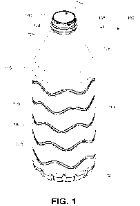
100081 FIG. 1 is a perspective view of an example of an embodiment
of a bottle illustrating a
plurality of offset wave grooves.
100091 FIG. 2 is a bottom perspective view of the bottle shown in
FIG. 1.
100101 FIG. 3 is a side view of the bottle shown in FIG. 1.
100111 FIG. 3A is a side view of another example of an embodiment of
a bottle illustrating a
plurality of offset wave grooves, and more specifically three total grooves.
100121 FIG. 4 is a cross-sectional view of a groove of the bottle
shown in FIG. 1.
100131 FIG. 5 is a cross-sectional view of another example of an
embodiment of the groove
of the bottle shown in FIG. 1.
2
CA 03171342 2022- 9- 12
WO 2021/183810
PCT/US2021/021977
[0014] FIG. 6 is a side view of the bottle shown in FIG. 1
illustrating a plurality of
circumferentially offset grooves.
[0015] FIG. 7A is a cross-sectional view of the bottle shown in FIG.
6, taken along line 7-7
of FIG. 6, illustrating an angular distance between a valley of a first groove
and a peak of an
adjacent second groove.
[0016] FIG. 7B is a cross-sectional view of the bottle shown in FIG.
6, taken along line 7-7
of FIG. 6, illustrating an angular distance between a first peak of the first
groove and a closest
second peak of the adjacent second groove.
[0017] FIG. 8 is a side view of the bottle shown in FIG. 1
illustrating a diverted load path
and improved hoop-wise strength generated by the plurality of
circumferentially offset grooves.
[0018] Before embodiments of the disclosure are explained in detail,
it is to be understood
that the disclosure is not limited in its application to the details of
construction and the
arrangement of components set forth in the following description or
illustrated in the
accompanying drawings The disclosure can support other embodiments and of
being practiced
or of being carried out in various ways
DETAILED DESCRIPTION
[0019] The present disclosure illustrates a container 100 that
includes a plurality of offset
wave grooves that improve structural strength of the container 100, which can
reduce risk of
damage, leakage, bending, or undue stresses on the container 100. The
container 100 illustrated
in the figures is a bottle 100, and further an approximately one-liter bottle.
It should be
appreciated that the bottle 100, and specifically the one-liter bottle, is
provided for purposes of
illustration and is not limiting. The bottle 100 can be any suitable or
desired size and/or volume.
For example, the bottle 100 can be, for example, 250 milliliters (mL), 1.0
Liter (L), 2.0 L, 8
ounces (oz.), 12 oz., 16.9 oz., 20 oz., 24 oz., or any other suitable or
desired size or volume. In
addition, the bottle 100 can be formed of a plastic or a polymer. For example,
the bottle 100 can
be formed of polyethylene terephthalate (PET), or any other suitable material
or combination of
materials. The plurality of offset wave grooves described herein can be used
with any type of
3
CA 03171342 2022- 9- 12
WO 2021/183810
PCT/US2021/021977
suitable container or vessel, or any size of suitable bottle that benefits
from improved strength
properties, including improved structural strength.
[0020] Now with reference to the figures, FIGS. 1-5 illustrate the
container 100 (also
referred to as the bottle 100). With specific reference to FIGS. 1-3, the
bottle 100 includes a
sidewall 104, a bell 108 and a base 112. The sidewall 104 (also referred to as
a body 104)
extends between the bell 108 and the base 112. A shoulder 116 can be provided
between the
sidewall 104 and the bell 108 to provide a transition between the sidewall 104
and the bell 108.
The bell 108 extends upward and inward relative to a central axis 120 (shown
in FIG. 3) from the
sidewall 104 to a neck 124 and a finish 128. As shown in FIG. 3, the central
axis 120 extends
from the finish 128 to the base 112. Referring back to FIGS. 1-3, the neck 124
is coupled to the
bell 108, and the finish 128 is coupled to the neck 124. The finish 128
defines a bottle opening
132 (or an opening 132 or an orifice 132) (shown in FIG. 1) that leads to an
interior of the bottle
100. As shown in FIG. 1, the finish 128 includes a thread 136 and a sealing
surface 140. The
thread 136 is configured to engage a closure (or a cap) (not shown). The
sealing surface 140
defines a circumferential perimeter end of the opening 132. The sealing
surface 140 is
configured to engage with a portion of the closure (not shown) to seal the
opening 132. A neck
ring 144 (also referred to as a transfer bead 144) circumferentially extends
around the neck 124
and is positioned between the finish 128 and the neck 124. The interior of the
bottle 100 is
configured to contain a beverage, a liquid, and/or any other suitable
contents. In the illustrated
embodiment, the bell 108 has a frustoconical cross-sectional shape, with the
bell 108 having a
first, smaller cross-sectional diameters adjacent the neck 124, and a second,
wider cross-sectional
diameter adjacent the sidewall 104. In other examples of embodiments, the bell
108 can have any
suitable cross-sectional shape or geometry (e.g., arcuate, domed, semi-
spherical, cupola-like,
etc.) desired for the bottle 100. In addition, the sidewall 104 is illustrated
as generally cylindrical.
However, in other embodiments, the sidewall 104 can be any suitable or desired
cross-sectional
shape or geometry (e.g., sloped with an increasing cross-sectional diameter,
sloped with a
decreasing cross-sectional diameter, form an hourglass-like cross-sectional
shape where a
portion of the sidewall has a cross-sectional diameter that is smaller than a
portion above and/or
a portion below, etc.). In addition, the sidewall 104 can include additional
or different features,
including curvatures, tapers, handles, grips, etc.
4
CA 03171342 2022- 9- 12
WO 2021/183810
PCT/US2021/021977
[0021] With reference to FIGS. 1 and 3, the sidewall 104 includes a
plurality of grooves 200
(otherwise referred to as ribs 200). Each groove 200 extends around a
circumference of the
sidewall 104. In other examples of embodiments, each groove 200 can extend
around a portion
of the circumference of the sidewall 104, or partially extend around the
circumference of the
sidewall 104. For example, each groove 200 can be defined by a plurality of
groove sections to
form an intermittent or broken groove around the circumference of the sidewall
104. In the
illustrated embodiment, the bottle 100 includes five total grooves 200. In
other embodiments, the
bottle 100 can include any suitable number of grooves 200 (e.g., two, three,
four, six, seven,
eight, nine, or ten or more). As a nonlimiting example, FIG. 3A illustrates a
bottle 100', shown
as a 250 mL bottle, that includes three grooves 200. Generally, the bottle 100
includes at least
two grooves 200. In other embodiments, the bell 108 and/or the base 112 can
also include at least
one groove 200.
[0022] With specific reference to FIG. 3, the plurality of grooves
200 are vertically separated
(or vertically spaced) along the central axis 120. Stated another way, the
grooves 200 are
longitudinally separated (or spaced) along the longitudinally extending
central axis 120. In the
illustrated embodiment, the grooves 200 are stacked, but spaced apart. The
grooves 200 are
equally spaced apart, such that a vertical distance between consecutive
grooves 200 (or adjacent
grooves) is the same along the central axis 120. In other embodiments, the
grooves 200 can be
unequally spaced apart, such that a vertical distance between two consecutive
grooves 200 of the
plurality of grooves 200 can be greater than or less than a vertical distance
between two other
consecutive grooves 200 of the plurality of grooves 200. It should be
appreciated that the
plurality of grooves 200 includes at least two grooves 200a, 200b.
[0023] Each groove 200 defines a wavelike pattern that extends
around the circumference of
the sidewall 104. Each wave includes a plurality of peaks 204, a plurality of
valleys 208, and a
plurality of transition sections 212. Each transition section 212 extends
between each adjacent
peak 204 and valley 208 (or each adjacent valley 208 and peak 204). The peaks
204 are generally
positioned closer to the bell 108 than the base 112, while the valleys 208 are
generally positioned
closer to the base 112 than the bell 108. In the illustrated embodiment, each
groove 200 is
sinusoidal in that the peaks 204 and the valleys 208 have the same amplitude
(or extend the same
distance from a common origin)_ In addition, the peaks 204 and the valleys 208
of each groove
CA 03171342 2022- 9- 12
WO 2021/183810
PCT/US2021/021977
200 are rounded (or U-shaped). In other examples of embodiments, the peaks 204
and the valleys
208 of each groove 200 can be angled (or V-shaped), or can be generally flat
(i.e., can have a
surface parallel to the circumference of the sidewall 104. The plurality of
grooves 200 have an
identical pattern of peaks 204, valleys 208, and transition sections 212, such
that the plurality of
grooves 200 have the same general shape, the same amplitude, the same
wavelength, and/or have
the same dimensions between consecutive peaks 204. However, as discussed in
additional detail
below, each groove 200 of the plurality of grooves 200 is offset from the
adjacent groove 200. In
other embodiments, each of the plurality of grooves 200 can have a different
pattern of peaks
204, valleys 208, and transition sections 212, while still being offset from
the adjacent groove
200. Each groove 200 includes a total of six peaks 204 and six valleys 208. In
other examples of
embodiments, each groove 200 can include any suitable number of peaks 204
(e.g., two, three,
four, seven, eight, nine, or ten or more), and any suitable number of valleys
208 (e.g., two, three,
four, seven, eight, nine, or ten or more). In other examples of embodiments,
the peaks 204 of a
groove 200 can have the same amplitude (or extend the same vertical distance
towards the bell
108) or can have different amplitudes (or extend different vertical distances
towards the bell
108). Similarly, in other examples of embodiments, the valleys 208 of a groove
200 can have the
same amplitude (or extend the same vertical distance towards the base 112) or
can have different
amplitudes (or extend different vertical distances towards the base 112). In
yet other examples of
embodiments, a groove 200 can have peaks 204 and valleys 208 that each have
different
amplitudes. For example, the peaks 204 can have a different amplitude than the
valleys 208. In
addition, the peaks 204 can have different amplitudes between peaks 204, and
the valleys 208
can have different amplitudes between valleys 208. Further, the amplitudes of
the peaks 204 can
be different than the amplitudes of the valleys 208.
100241 With reference now to FIG. 4, a cross-sectional view of the
groove 200 is illustrated.
The groove 200 includes opposing groove sidewalls 216 and a bottom wall 220.
Each groove
sidewall 216 is inclined (or sloped) from the sidewall 104 (of the bottle 100)
to the bottom wall
220. The bottom wall 220 is flat (or substantially flat). The groove 200 has a
depth D, as
measured from the sidewall 104 to the bottom wall 220. In the illustrated
embodiment, the depth
D is in the range of approximately 0.8 millimeters (mm) to approximately 5.0
mm. In other
embodiments, the depth D can be approximately 0.8 mm, 0.9 mm, 1.0 mm, 1.5 mm,
2.0 mm, 2.5
6
CA 03171342 2022- 9- 12
WO 2021/183810
PCT/US2021/021977
mm, 3.0 mm, 3.5 mm, 4.0 mm, 4.5 mm, or 5.0 mm. In yet other embodiments, the
depth D can
be any suitable or desired depth.
[0025] The groove 200 has a maximum width W, as measured between
ends of the groove
sidewalls 216 proximate the sidewall 104 (of the bottle 100). In the
illustrated embodiment, the
width W is in the range of approximately 2.0 mm to approximately 6.0 mm. In
other
embodiments, the width W can be approximately 2.0 mm, 3.0 mm, 4.0 mm, 5.0 mm,
or 6.0 mm.
In yet other embodiments, the width W can be any suitable or desired width. In
addition, the
maximum width is greater than a width of the bottom wall 220. As such, the
groove 200 has a
cross-sectional geometry similar to a trapezoid (or a trapezoidal cross-
sectional shape).
[0026] The groove 200 has a first radius R1 between the sidewall
104 (of the bottle 100) and
each of the groove sidewalls 216. In the illustrated embodiment, the first
radius R1 is
approximately 1.0 mm. In other embodiments, the first radius R1 can be any
suitable or desired
radius length.
[0027] The groove has a second radius R2 between each groove
sidewall 216 and the bottom
wall 220. In the illustrated embodiment, the second radius R2 is less than the
first radius R1 . In
other examples of embodiments, the second radius R2 is greater than the first
radius Rl. In yet
other examples of embodiments, the second radius R2 is the same as the first
radius R1 .
[0028] Each groove sidewall 216 has a length Li. In the illustrated
embodiment, the length
Li of the groove sidewalls 216 are approximately 1.51 mm. In other
embodiments, the length Li
of the groove sidewalls 216 can be any suitable or desired length.
[0029] An angle X can extend between the groove sidewalls 216. In
the illustrated
embodiment, the angle X can be approximately 55 degrees. In other
embodiments, the angle X
can be less than 55 degrees, can be more than 55 degrees, or can be any
suitable or desired angle.
100301 With reference to FIG. 5, a cross-sectional view of another
example of the groove
200' is illustrated. The groove 200' is substantially the same as groove 200,
with like number
identifying like components, and like variables identifying like ranges. The
groove 200' differs
in that the bottom wall 220 is curved (or arcuate), instead of flat (or
substantially flat) as shown
in groove 200.
7
CA 03171342 2022- 9- 12
WO 2021/183810
PCT/US2021/021977
[0031] With reference now to FIGS. 3 and 6, the plurality of grooves
200 are
circumferentially offset from one another. More specifically, each groove 200
of the plurality of
grooves 200 is circumferentially offset from an adjacent groove 200. As such,
the peaks 204, the
valleys 208, and/or the transition sections 212 of one groove 200 are not in
vertical alignment (or
are not vertically aligned relative to the central axis 120) with the peaks
204, the valleys 208,
and/or the transition sections 212 of the adjacent groove 200 It should be
appreciated that the
term adjacent groove 200 can include the immediately next groove 200 above
and/or below one
of the grooves 200.
[0032] With reference to FIG. 6, a first groove 200a of the
plurality of grooves 200 includes
a plurality of peaks 204 and a plurality of valleys 208. A second groove 200b
of the plurality of
grooves 200, which is adjacent the first groove 200a, also includes a
plurality of peaks 204 and a
plurality of valleys 208. To illustrate the circumferentially offset
arrangement of adjacent
grooves 200, the first groove 200a includes a first valley Vi and a first peak
Pi. The second
groove 200b includes a second valley V2 and a second peak P2. The second
valley V2 of the
second groove 200b corresponds to the first valley Vi of the first groove
200a. Stated another
way, the first and second valleys Vi, V2 are the same valleys in different
grooves 200a, 200b.
The second valley V2 is horizontally translated (or shifted) around an outer
perimeter of the
sidewall 104 (or circumferentially offset) relative to the first valley Vi.
Stated another way, the
first valley Vi is horizontally translated (or shifted) around an outer
perimeter of the sidewall 104
(or circumferentially offset) relative to the second valley V2. Similarly, the
second peak P2 of the
second groove 200b corresponds to the first peak Pi of the first groove 200a.
Stated another way,
the first and second peaks Pi, P2 are the same peaks in different grooves
200a, 200b. The second
peak P2 is horizontally translated (or shifted) around an outer perimeter of
the sidewall 104 (or
circumferentially offset) relative to the first peak Pi. Stated yet another
way, the first peak Pi is
horizontally translated (or shifted) around an outer perimeter of the sidewall
104 (or
circumferentially offset) relative to the second peak P2. It should be
appreciated that the first
groove 200a can be any one of the plurality of grooves 200, and the second
groove 200b can be
any groove 200 that is adjacent the first groove 200a (i.e., a groove 200
above or below the first
groove 200a).
8
CA 03171342 2022- 9- 12
WO 2021/183810
PCT/US2021/021977
[0033] With reference to FIG. 7A, the circumferentially offset
arrangement of the first and
second grooves 200a, 200b is illustrated by a first angle 01. The first angle
Otis defined as the
angular distance (in degrees) between the first valley Vi of the first groove
200a and the second
peak P2 of the second groove 200b (shown in FIG. 6). This can also be referred
to as an angular
distance measured from valley to peak of adjacent grooves 200a, 200b. The
first angle 01 can be
in the range of approximately 5 degrees to approximately 80 degrees. More
specifically, the first
angle 01 can be in the range of approximately 25 degrees to approximately 60
degrees. More
specifically, the first angle 01 can be in the range of approximately 25
degrees to approximately
50 degrees. More specifically, the first angle 01 can be in the range of
approximately 35 degrees
to approximately 55 degrees. More specifically, the first angle 01 can be in
the range of
approximately 35 degrees to approximately 45 degrees. More specifically, the
first angle 01 can
be in the range of approximately 40 degrees to approximately 50 degrees. More
specifically, the
first angle Olean be approximately 40 degrees. More specifically, the second
angle 02 can be
approximately 25, 26, 27, 28, 229, 30, 31, 32, 33, 34, 35, 36, 37, 38, 39, 40,
41, 42, 43, 44, 45,
46, 47, 48, 49, or 50 degrees. All of the above approximations can be plus or
minus
approximately 5 degrees.
[0034] With reference to FIG. 7B, the circumferentially offset
arrangement of the first and
second grooves 200a, 200b is illustrated by a second angle 02. The second
angle 02 is defined as
the angular distance (in degrees) between the first peak Pi of the first
groove 200a and the second
peak P2 of the second groove 200b (shown in FIG. 6). This can also be referred
to as an angular
distance measured from peak to peak of adjacent grooves 200a, 200b (or the
angular distance
between the first peak Pi of the first groove 200a and the angularly closest
peak P2 of the
adjacent second groove 200b). The second angle 02 can be in the range of
approximately 5
degrees to approximately 45 degrees. More specifically, the second angle 02
can be
approximately 5, 6, 7, 8, 9, 10, 11, 12, 13, 14, 15, 16, 17, 18, 19, 20, 21,
22, 23, 24, 25, 26, 27,
28, 29, 30, 31, 32, 33, 34, 35, 36, 37, 38, 39, 40, 41, 42, 43, 44, or 45
degrees. All of the above
approximations can be plus or minus approximately 5 degrees. It should be
appreciated that in
embodiments where the adjacent grooves 200a, 200b have the same general shape
and are
circumferentially offset from each other, the angular distance as measured
from peak to peak (or
from the first peak Pi to the second peak P2) will be the same as the angular
distance as measured
9
CA 03171342 2022- 9- 12
WO 2021/183810
PCT/US2021/021977
from valley to valley (or between the first valley Vi of the first groove 200a
and the angularly
closest, second valley V2 of the second groove 200b (shown in FIG. 6)).
[0035] The plurality of circumferentially offset grooves 200
advantageously improve load
strengthening. More specifically, the grooves 200 disrupt a downward load path
to provide
additional strength to the bottle 100. With reference to FIG. 8, the
circumferentially offset
grooves 200 of the bottle 100 divert (or break up) a load path, illustrated by
arrows 404. The
curved, downward arrows 404 indicate a path of load disruption caused by the
plurality of
circumferentially offset grooves 200 More specifically, the circumferentially
offset grooves 200
directs a downward force from a valley 208 of one groove 200 (or 200a) towards
the closest peak
204 of an adjacent groove 200 (or 200b) positioned on the base side of the
groove 200 (or 200a).
The additional strength reduces a risk of buckling (or failure) of the
sidewall 104 as compared to
aligned grooves, where the downward load path is generally parallel to the
central axis 120
(shown in FIG. 6). In addition, the circumferentially offset grooves 200
provided improved hoop
strength (or hoop-wise strength, or circumferential strength, or strength in a
circumferential
direction), shown by arrows 408. The increase in hoop-wise strength is
achieved as the load is
diverted (or broken up) in the longitudinal / axial direction. Thus,
advantageously, the downward
load is provided partially downwards and partially in a twisting action.
100361 Table I below illustrates the load effectiveness of
disruption / strengthening (as a
percentage or %). The angle described in Table I below illustrates the first
angle 01 shown in
FIG. 7A, defined as the angular distance (in degrees) between the first valley
Vi of the first
groove 200a and the second peak P2 of the adjacent second groove 200b. The
effectiveness
strengthening of Table I is measured by the first major drop in torsional
resistive force, which
signifies the first major failure of the sidewall 104.
Table I: Effectiveness Values for Wave Alignment
Angle (degrees) Effectiveness of
disruption/strengthening (%)
0 0
18
22
31
42
35
28
CA 03171342 2022- 9- 12
WO 2021/183810
PCT/US2021/021977
70 21.6
[0037] Table II below illustrates how changing the circumferential
offset (or alignment) of
adjacent grooves 200a, 200b can improve load performance. The angle described
in Table II
below illustrates the first angle 01 shown in FIG. 7A, defined as the angular
distance (in degrees)
between the first valley Vi of the first groove 200a and the second peak P2 of
the adjacent second
groove 200b. The top load increase is measured as a percentage change from
zero degrees of
angular offset (or vertically aligned grooves), as measured by the first major
drop in downward
resistive force, which signifies the first major failure of the sidewall 104.
Table II: Load Values for Wave Alignment
Angle (degrees) Top Load Increase (%)
0 0
10 3.5
20 4.7
30 6.6
40 8.5
50 8.0
60 6.1
70 5.2
100381 Based on the results listed in Table II, embodiments of the
bottle 100 that incorporate
a plurality of circumferentially offset grooves 200 can have a load strength
increase in the range
of approximately 3.0% to approximately 8.5% as compared to a bottle without
offset grooves
(such as a bottle with circumferentially aligned grooves). More specifically,
the bottle 100 can
have a load strength increase of at least approximately 3.0%, 4.0%, 5.0%,
6.0%, 7.0%, 8.0%, or
8.5% as compared to a bottle without offset grooves (such as a bottle with
circumferentially
aligned grooves). In other embodiments, the load strength increase of the
bottle that incorporates
a plurality of circumferentially offset grooves 200 can be greater than 8.5%
or less than 3.0%
based on the size, dimensions, material, geometry, and/or other variables
associated with bottle
design.
[0039] The illustrated embodiment of the bottle 100 presents a plurality
of circumferentially
offset grooves 200, where each groove 200, 200a includes a plurality of peaks
204 and a plurality
of valleys 208 that are not in vertical alignment with (or are
circumferentially offset from) the
plurality of peaks 204 and the plurality of valleys 208 in an adjacent groove
200, 200b It should
11
CA 03171342 2022- 9- 12
WO 2021/183810
PCT/US2021/021977
be appreciated that in other examples of embodiments, the plurality of grooves
200 can include a
groove 200, 200a that includes at least one peak 204 that is not in vertical
alignment with (or is
circumferentially offset from) at least one peak 204 in an adjacent groove
200, 200b. In yet other
examples of embodiments, the plurality of grooves 200 can include a groove
200, 200a that
includes at least one valley 208 that is not in vertical alignment with (or is
circumferentially
offset from) at least one valley 208 in an adjacent groove 200, 200b.
100401 It should be appreciated that the bottle 100 includes at
least two grooves 200a, 200b,
and the at least two grooves 200a, 200b are circumferentially offset (or not
vertically aligned
relative to the central axis 120. In other examples of embodiments, the bottle
100 includes a
plurality of grooves 200, and each groove 200 is circumferentially offset
relative to the adjacent
groove 200. Each groove 200 of the plurality of grooves 200 can be
circumferentially offset
relative to the adjacent groove 200 by the same angular distance (e.g., as
illustrated in FIGS. 1-
3), or a different angular distance (e.g., within the plurality of grooves
200, a first pair of
adjacent grooves 200 is circumferentially offset a different angular distance
than a second pair of
adjacent grooves 200, etc.).
100411 In yet other examples embodiments, the plurality of grooves
200 can have an
alternating circumferentially offset geometry. For example, every other groove
200 of the
plurality of grooves 200 can be vertically aligned relative to the central
axis 120, however, any
two adjacent grooves 200 are circumferentially offset. Stated another way, and
as a nonlimiting
example, in an embodiment of a bottle 100 having a plurality of grooves 200
that includes at
least four grooves 200 vertically spaced along the central axis 120, a second
groove 200 can be
circumferentially offset from an adjacent first groove 200, the first groove
being closer to the bell
108 than the second groove 200. A third groove 200 can be circumferentially
offset from the
adjacent second groove 200, the second groove being closer to the bell 108
than the third groove
200. A fourth groove 200 can be circumferentially offset from the adjacent
third groove 200, the
third groove being closer to the bell 108 than the fourth groove 200. The
first and third grooves
200 can be vertically aligned relative to the central axis 120, and the second
and fourth grooves
200 can be vertically aligned relative to the central axis 120. In this
configuration, each groove
200 is circumferentially offset by being rotated (or horizontally translated)
either in a clockwise
direction or a counterclockwise direction relative to the adjacent groove 200.
In one or more
12
CA 03171342 2022- 9- 12
WO 2021/183810
PCT/US2021/021977
examples of embodiments, the angular distance defining the circumferential
offset can be the
same or can be different between adjacent pairs of grooves 200 within the
plurality of grooves
200.
100421 In yet other examples of embodiments, the plurality of
grooves 200 can have an
alternating circumferentially offset geometry, however every other groove 200
of the plurality of
grooves 200 is not vertically aligned relative to the central axis 120. Stated
another way, and as a
nonlimiting example, in an embodiment of a bottle 100 having a plurality of
grooves 200 that
includes at least four grooves 200 vertically spaced along the central axis
120, a second groove
200 can be circumferentially offset from an adjacent first groove 200, the
first groove being
closer to the bell 108 than the second groove 200. A third groove 200 can be
circumferentially
offset from the adjacent second groove 200, the second groove being closer to
the bell 108 than
the third groove 200. A fourth groove 200 can be circumferentially offset from
the adjacent third
groove 200, the third groove being closer to the bell 108 than the fourth
groove 200. The second
groove 200 is circumferentially offset from the first groove 200 by being
horizontally translated
a first distance (or having a first angular distance) in a first direction
relative to the first groove
200. The third groove 200 is circumferentially offset from the second groove
200 by being
horizontally translated a second distance (or having a second angular
distance) in a second
direction, opposite the first direction, relative to the second groove 200.
The absolute value of the
second distance (or the second angular distance) is not the same absolute
value as the first
distance (or the first angular distance). The fourth groove 200 is
circumferentially offset from the
third groove 200 by being horizontally translated a third distance (or having
a third angular
distance) in the first direction relative to the third groove 200. The
absolute value of the third
distance (or the third angular distance) is not the same absolute value as the
first distance (or the
first angular distance) or the second distance (or the second angular
distance).
100431 The illustrated embodiment of the bottle 100 discusses the
circumferentially offset
orientation of adjacent grooves 200a, 200b of the plurality of grooves. It
should be appreciated
that the offset between two grooves 200 that are not adjacent can be
determined. For example,
and with reference to FIG. 8, the circumferential offset between the first
groove 200a and a third
groove 200c that is not adjacent to the first groove 200a can be determined by
multiplying the
angular distance between the first groove 200a and the adjacent second groove
200b (e.g., the
13
CA 03171342 2022- 9- 12
WO 2021/183810
PCT/US2021/021977
first angle 01, the second angle 02, etc.) by one plus the total number of
grooves between the first
and third grooves 200a, 200c. As a nonlimiting examples, in the illustrated
example in FIG. 8, if
the angular distance between the first and second grooves 200a, 200b is
hypothetically 5 degrees,
the angular distance between the first and third grooves 200a, 200c is (5
degrees) x (1 + 3
grooves between the first and third grooves 200a, 200c) = (5 degrees) x (4) =
20 degrees.
100441 With reference back to FIGS. 3 and 6, in one or more examples
of embodiments,
adjacent grooves 200a, 200b can be shifted approximately 80, 81, 82, 83, 84,
85, 86, 87, 88, 89,
90, 91, 91.9, 92, 93, 94, or 95 mm in a horizontal direction. In one or more
examples of
embodiments, a vertical distance between peaks 204 (e.g., Pi to P2, etc.) of
adjacent grooves
200a, 200b can be approximately 15, 16, 17, 18, 19, 20, 21, 22, 23, 24, 25,
26, 27, 28, 29, 30, 31,
32, 33, 34, or 35 mm. In one or more examples of embodiments, a vertical
distance between a
valley 208 of the first groove 200a and a peak 204 of an adjacent second
groove 200b can be
approximately 10, 11, 12, 13, 14, 15, 16, 17, 18, 19, or 20 mm. In one or more
examples of
embodiments, one or more of the grooves 200 can have an amplitude of
approximately 10, 11,
12, 13, 14, 15, 16, 17, 18, 19, or 20 mm. In one or more examples of
embodiments, one or more
of the grooves 200 can have a period of approximately 25, 26, 27, 28, 29, 30,
31, 32, 33, 34, 35,
36, 37, 38, 39, 40, 41, 42, 43, 44, or 45 mm.
100451 One or more aspects of the bottle 100 provides certain
advantages. For example, the
sidewall 104 includes a plurality of grooves 200, and more specifically at
least two grooves
200a, 200b. The plurality of grooves 200 are circumferentially offset from
each other. The
circumferential offset arrangement of the grooves 200 advantageously improve
load
strengthening by disrupting a downward load path. The load is diverted in a
curved, downward
direction by the circumferentially offset grooves 200. More specifically, the
load is diverted from
a valley 208 of one groove 200 (or 200a) towards the closest peak 204 of an
adjacent, offset
groove 200 (or 200b) positioned on the base side of the groove 200 (or 200a).
The additional
strength reduces a risk of buckling (or failure) of the sidewall 104, while
also increasing strength
in a hoop (or circumferential) direction. These and other advantages are
realized by the
disclosure provided herein.
14
CA 03171342 2022- 9- 12