Note: Descriptions are shown in the official language in which they were submitted.
CA 03171830 2022-08-17
SMALLARM COMPRISING EXTRACTOR UNIT
The invention relates to a smallarm having an extractor unit, and to such an
extractor unit for
a smallarm, corresponding to the preamble of claim 1.
The invention is explained in the following with reference to a blowback
system for pistols; a
person skilled in the art can, in knowledge of the invention and the following
examples,
easily transfer this system to other form-fit or force-fit locking systems for
smallarms, such as
rotating bolts.
In general, it can be stated for the operation of smallarms that after a
cartridge has been fired,
the empty cal __ Li idge case must be removed from the cal Li idge chamber
of a smallarm as
reliably as possible before a new cartridge can be supplied during the
reloading process.
Similarly, reliable removal of an unfired cartridge from the cartridge chamber
may be
required for unloading or repeating processes, which are carried out e.g.
during training with
the weapon.
In this case, an extractor is brought into engagement with the cal ____ tlidge
case, usually during
the loading and locking process. When the breech is opened, there is often a
backward
movement and/or a tilting movement of the breechblock, as a result of which
the cartridge
case is pulled out of the cartridge chamber. This relative movement is
completed with the
process of expelling the cal tlidge or case, in which an ejector forces the
cartridge case away
to one side or flings it out of the smallarm by striking the cal tlidge
case, usually when an
expulsion opening is reached. The ejector can be fixed to the receiver, for
example in the grip
(also known as the pistol frame), or it can also be moved when a shot is
fired, if it is arranged
e.g. in the slide, or in a movable bolt head. These processes have been known
to a person
skilled in the art for a long time and therefore do not require further
explanation at this point.
In most cases, extractors have a talon or claw shape on the cal _______ Li
idge-facing side in order to
ensure good contact with a groove or the edge of the emu idge.
Very often, an extractor unit is designed similarly to a rocker in terms of
shape and function
and is movably mounted in the receiver or the slide by means of a bearing pin
or peg. A
spring applies a force to one lever arm of the extractor, thus pre-loading the
second lever arm
1
Date Regue/Date Received 2022-08-17
CA 03171830 2022-08-17
toward the inside of the weapon. US 8,887,427 B2 should be mentioned at this
point merely
as an example of such a rocker design.
However, extractor units of this kind require a certain amount of installation
space, as
otherwise too little leverage on the extractor can lead to impaired
functioning. In addition, the
bearing pin is designed, relative to the surrounding components, as a
relatively delicate
component which is difficult or even impossible to dismantle under operating
conditions,
which makes it considerably harder to clean and maintain the extractor unit.
In the case of smallarms, in particular pistols, a further concept has become
widespread with
the introduction of GLOCK pistols in the 1980s. Here, the extractor is stirrup-
shaped, or
substantially U-shaped, and is pre-loaded in the slide toward the central
plane of the weapon
by means of a spring-loaded depressor plunger. The stirrup-shaped extractor
comprises a first
bearing lever which can be slightly wider than the connection segment to the
second lever,
the extractor lever. The bearing lever is often substantially cask-shaped and
is used for
mounting in a bearing opening of the slide which extends outward radially with
respect to the
barrel bore axis and is no longer visible from the outside due to the
insertion of the extractor.
This bearing opening allows a stable fit of the extractor and limited movement
of the
extractor about a tilting axis, which is normal and laterally offset with
respect to the barrel
.. bore axis. The second extractor lever is used for temporary contact with a
cartridge case and
is deflected slightly "outward" over the edge of the cartridge base during the
locking process,
in order to engage with said base or a groove provided for this purpose.
US 9,062,926 B2, US 5,794,373 A, US 2011/252686 Al or US 9,784,514 B1 are
cited as
examples of such extractor units and developments thereof. The contents of
these documents
and those of US 8,887,427 B2, the US 1,377,629 A and US 2004/0159032 Alas well
as the
EP 2 860 484 Al, which is dealt with further down, are incorporated by
reference into the
contents of the disclosure of this application for the jurisdictions where
this is possible.
In the documents mentioned, the bearing lever is usually cask-shaped and is
pushed from
"behind" in the direction of the central weapon plane, or the barrel bore
axis, by means of the
spring-loaded depressor plunger in the installed state. In addition, there may
be a step at the
rear, at the "back" as viewed in the installation situation, which step
prevents the extractor
2
Date Regue/Date Received 2022-08-17
CA 03171830 2022-08-17
from falling out due to the depressor plunger. This concept provides high
mechanical stability
and has proven to be very reliable.
It is also clear from the above-mentioned documents that the depressor plunger
assembly,
comprising an elongated cylindrical depressor plunger and at least one
depressor plunger
spring, that is arranged in a borehole inside the slide. On the rear side,
another spring bearing
can be provided between the depressor plunger spring and the slide cover
plate. The borehole
for receiving the depressor plunger assembly is preferably at a slightly
oblique angle with
respect to the barrel bore axis, as is clear, inter alia, from US 2011252686
Al.
In order to produce such an oblique borehole relative to the centrally
extending firing pin
receiving borehole, however, greater manufacturing outlay is required than
would be the case
with a parallel borehole, for example. This naturally requires more set-up
effort and time,
which in turn results in higher production costs.
Moreover, in the case of stirrup-shaped extractors, depressor plunger
assemblies known to
date are to be introduced "from behind" into the slide and are usually locked
in the slide by
means of a cover plate and the depressor plunger spring is thus tensioned. The
disassembly
and/or assembly of these depressor plungers to be tensioned from "behind"
requires some
degree of practice and is usually not intended for regular cleaning of the
weapon, but instead
should be carried out by a person skilled in the art or by specially trained
personnel. This is
all the more applicable in order to avoid scratching the surface of the weapon
during
disassembly/assembly with a tool and to prevent possible optical defects
and/or corrosion.
Furthermore, in the prior art, for the most part only extractor units in which
the depressor
plunger is visible from the outside are known to date. Owing to the
construction, a small gap
is often formed between the slide and the extractor. Said gap is generally not
protected
against the ingress of dust or foreign bodies, and a closed surface, or a
concealed functional
unit, such as that of the extractor unit, is more aesthetically pleasing to
most users than an
arrangement of, e.g., corners and edges or even recesses. In addition,
plastics materials are
increasingly used for individual components of a firearm, such as for forming
the slide cover
plate on the rear side. It is therefore desirable to avoid, as far as
possible, scratching these
components by disassembly/assembly of the slide and/or the extractor unit
during
maintenance and cleaning work.
3
Date Regue/Date Received 2022-08-17
CA 03171830 2022-08-17
Moreover, small dimensions of the extractor unit with the simplest possible
disassembly/assembly are desired.
The object of the invention is therefore to provide an extractor unit which is
as compact and
stable as possible and is also as easy to manufacture as possible. It is also
an object according
to the invention to provide an extractor unit which is as well-protected as
possible against
accidental disassembly and also has an outer contour of the weapon which is as
closed as
possible.
In order to achieve the above-mentioned objects, a smallarm according to the
invention
comprises the features of the characterizing part of claim 1. In other words,
it has a slide, an
ejector and an extractor unit; the extractor unit comprises a stirrup-shaped
extractor, a plunger
and a biasing element. The extractor is stirrup-shaped, similar to that in the
documents
mentioned above, and has a first bearing lever, facing the plunger in the
installed state, for
mounting in the slide, and a second extractor lever provided for temporary
contact with a
cartridge case. According to the invention, the plunger comprises a plunger
body and a
plunger extension, the plunger body being provided for reception and mounting
together with
the biasing element in a frame. The slide of the smallarm further comprises a
reception for
the frame, and a maintenance bore in the region of the plunger body, which
bore penetrates
the slide in the direction of the reception in the installed state.
By forming a frame, the biasing element and the plunger body can
advantageously be
assembled outside the weapon, thus achieving a pre-loaded state of the
plunger. The use of a
frame also makes it possible to use a biasing element, preferably a spiral
spring, with very
high spring force. This in turn allows relatively small dimensions of the
extractor unit, while
relatively simple assembly, or, in reverse order, disassembly, is still
possible.
Furthermore, the design according to the invention of the extractor unit makes
it possible to
avoid the cost-intensive and time-intensive production of an oblique borehole
within the
slide. In principle, it would be sufficient to provide a reception in the
slide, which reception
has a substantially complementary shape to the external dimensions, such that
the frame can
be easily inserted from the front. Specific modifications may also be provided
according to
the description of the drawings.
4
Date Regue/Date Received 2022-08-17
CA 03171830 2022-08-17
In order to assemble the extractor unit, after the frame is inserted into the
reception, only the
plunger body is slightly deflected backward by a tool being inserted through a
maintenance
bore provided therefor in the slide, preferably from below. The tip of the
tool has the effect
that the plunger extension, which is deflected forward in a spring-loaded
manner on the
plunger body in the installation situation, is pushed backward. The extractor
can then be
inserted from the outside in a known manner and the blocking effect of the
plunger extension
on the extractor can be restored by removing the tool. Both the extractor and
the frame are
therefore secured in the slide against slipping and/or falling out.
In addition, the extractor unit is therefore very well concealed inside the
handgun and
preferably only one side of the frame is substantially flush with the surface
of the slide. This
can achieve the most continuous surface possible in this region, without
additional openings,
edges or protrusions. This promotes, inter alia, the reduction of deposits in
the openings,
which can be caused by soil, dust, dirt, etc.
In particular, stirrup-shaped extractors, as in the embodiment according to
the invention, can
perform an additional function by temporary interaction with the firing pin
safety. In
handguns, preferably in pistols, a firing pin safety can be arranged at the
front end of the
firing pin, as is described very clearly in, inter alia, EP 2 860 484 Al. The
contents of this
document are incorporated by reference into the contents of the disclosure of
this application
for jurisdictions where this is possible.
Such a firing pin safety is operatively connected to the trigger bar and, when
the trigger bar is
operated, is moved such that the path of the firing pin is cleared. The firing
pin safety is, like
the extractor, mounted in the slide so as to be spring-loaded and has roughly
the shape of a
cylinder which has two opposing lateral recesses transversely to the
longitudinal axis. One of
these recesses, facing the central plane of the weapon, allows the firing pin
to move in the
release position, while the second recess, facing outward, is used for
temporary contact with
the extractor, which, due to this design, prevents the firing pin safety from
falling out when
the firing pin is pulled backward.
Other components of a smallarm, in particular of a pistol, such as the grip,
various safety
devices or the firing mechanism are not described in more detail in the
context of this
5
Date Regue/Date Received 2022-08-17
CA 03171830 2022-08-17
description, as the invention does not relate to these and a person skilled in
the art, having
knowledge of the description and/or the invention, can make any desired
modifications easily
and without difficulty based on his knowledge in the art.
The invention is explained in more detail in the following with reference to
the drawings, in
which:
Fig. 1 is a simplified exploded view of a slide according to the prior art;
Fig. 2 is a simplified exploded view of a slide having an extractor unit
according to the
invention;
Figs. 3 and 4 are horizontal sections corresponding to Figs. 1 and 2,
respectively;
Figs. 5 and 6 are vertical sections corresponding to Figs. 1 and 2,
respectively;
Fig. 7 is a schematic illustration of the disassembly process:
a) when inserting the tool,
b) when releasing the extractor, and
c) with the extractor removed;
Figs. 8a-c show different embodiments of frames;
Fig. 9a shows an extractor geometry according to the prior art;
Fig. 9b shows an embodiment according to the invention;
Fig. 10a is a schematic illustration of an extractor unit in the installation
situation,
Fig. 10b is a schematic illustration of an extractor unit in the operating
position; and
Figs. 1 la-c are schematic illustrations of different embodiments of plungers.
The terms left, right, above, below, front and back/behind always refer in the
following to the
view of the shooter in the firing direction of the firearm when it is held
ready to fire. The
weapon has, extending through the barrel axis and oriented vertically, a
central plane of the
weapon which, cum grano salis, forms a plane of symmetry.
Fig. 1 is an exploded illustration, by way of example, of the previously best-
known and most
widely used extractor unit 2 for GLOCK pistols. The schematic illustration
comprises a slide
1, in which a barrel 11 and a recoil spring assembly 12 can be received at the
bottom. A firing
pin safety 15 with spring can be introduced from below into a clearance
provided therefor in
the slide 1 and can, in the manner described above, be secured against falling
out by the
extractor 21. It can be very clearly seen in Fig. 1 that the firing pin
assembly 14, just like a
depressor plunger assembly 3 (Fig. 3) consisting of a depressor plunger 31, a
depressor
6
Date Regue/Date Received 2022-08-17
CA 03171830 2022-08-17
plunger spring 32, and a spring bearing 33, can be inserted from behind into
the slide 1 and
secured by means of the slide cover plate 16. The installed state can be seen
by viewing Fig.
1 in combination with Fig. 3, which also shows the borehole for the depressor
plunger
assembly 3, which borehole is formed obliquely with respect to the central
plane of the
weapon. In Fig. 1, several serrations 111 can be seen in the rear region of
the slide 1.
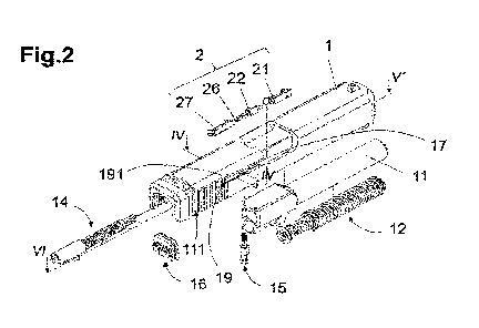
Fig. 2 is a schematic exploded view of a similar slide 1 of a pistol,
analogously to Fig. 1, but
with an extractor unit 2 designed according to the invention. It can be
directly seen that the
extractor unit 2 consists only of a frame 27, a biasing element 26 and a
plunger 22, which can
.. all now be inserted from the "front" into the slide 1 in order to interact
with the extractor 21.
Advantageously, the use of the frame 27 and the mounting of the plunger 22 and
the biasing
element 26 in the frame 27 makes it possible to assemble the plunger 22, and
subsequently to
pre-load the plunger 22 in the direction of the bearing lever 212, outside the
slide 1, which
makes it considerably easier to assemble this extractor unit 2.
Figs. 3 and 4 are each a section through a weapon along a horizontal plane in
the installation
situation, as seen in a viewing direction in the vertical direction 93 from
"above," in the
regions /MITT in Fig. 1 and the regions IV-IV' in Fig. 2, respectively. The
appearance of the
extractor 21 in Figs. 3 and 4 is slightly different due to the different
section planes, as a result
of which the firing pin safety 15 also looks different.
In the section in Fig. 3, the depressor plunger assembly 3 known from the
prior art and its
effect on the extractor 21 can clearly be seen. The extractor 21 is seated via
its bearing lever
212 (Fig. 9) in the bearing opening 17, as can also be seen in the variant
according to the
invention in Fig. 4, pre-loaded by the depressor plunger 31 in the direction
of the central
plane of the weapon. This process is carried out analogously in Fig. 4 by the
effect of the
plunger 22 on the bearing lever 212. In both cases, it can clearly be seen
that the depressor
plunger 31 and the plunger extension 222 (Fig. 6) of the plunger 22 engage in
a small
shoulder of the extractor 21 and allow a loss-proof arrangement. It is very
clearly visible from
the comparison of the two types of construction that the biasing element 26
and the plunger
22 are mounted in the frame 27 and are relatively well protected "outward" in
the normal
direction 92, while the depressor plunger 31, the depressor plunger spring 32
and the spring
bearing 33 must be introduced from "behind" and tensioned during assembly by
the insertion
of the slide cover plate 16.
7
Date Regue/Date Received 2022-08-17
CA 03171830 2022-08-17
For the sake of completeness, it should be noted that, although not shown
separately in Fig. 4,
it is also possible to arrange the ejector 18 so as to be fixed to the
receiver, as can be seen in
Fig. 3. The ejector 18 in Fig. 3 is fixed in a grip (not shown) and interacts
with the cal tlidge
case head in the manner described above, which is familiar to a person skilled
in the art.
Analogously thereto, Figs. 5 and 6 are cross sections through the weapon in
the vertical
direction 93 in the installed state, the viewing direction shown being from
the "right" in the
normal direction 92. Analogously to Figs. 3 and 4, the different extractor
units 2 can also be
very clearly seen in these illustrations.
The effect of the extractor unit 2 according to the invention and the
disassembly/assembly
thereof are explained by way of example with reference to Figs. 4, 6 and 7. A
maintenance
bore 191 is provided in the slide 1, which bore passes through the slide 1
substantially from
"below" in the vertical direction 93. The maintenance bore is provided in the
region of the
plunger body 221 such that a tool 4, or another narrow makeshift object, can
be inserted when
the weapon is partially dismantled in order to interact with the plunger body
221 such that the
plunger extension 222 is moved "backward." In the present example, in Fig. 7a
the tip of the
tool touches a chamfer 224 of the plunger body 221, as a result of which the
extractor 21 is
displaced and finally released (see Fig. 7b) and can be removed from the
weapon (cf. Fig.
7c). Subsequently, the tool can be removed and, if necessary, the frame 27 can
be moved
forward in the longitudinal direction of the weapon, in order to be removed
from the slide.
In order to ensure a good fit of the frame 27 in the slide 1 and to prevent an
"outward"
movement of the frame 27, it has proven advantageous for the reception 19 (see
also Fig. 2)
to be adapted to the cross-sectional shape of the frame 27, i.e. to have a
substantially
complementary shape thereto. The shape-complementary design of the reception
19 and the
frame 27 can be e.g. wedge-shaped, or formed by one or more shoulders, in
order to ensure
suitable support of the frame 27 in the slide 1.
It is particularly advantageous for at least one additional guide 271 to be
formed on the frame
27, which guide interacts with the shape-complementary reception 19. Such a
guide 271 on
the frame 27 can also be one- or double-sided and/or wedge-shaped, as would be
the case e.g.
with a dovetail profile. A "T-shaped" design of the cross section of the frame
27 or the
8
Date Regue/Date Received 2022-08-17
CA 03171830 2022-08-17
reception 19 is also conceivable. The design of guides 271 facilitates
insertion during
assembly of the frame 27 and provides an extremely stable fit with low surface
pressure of
the contact surfaces between the slide 1 and the frame 27.
Fig. 8 schematically shows several variants of frames 27, with such double-
sided guides 271
being clearly visible. In addition to providing loss prevention for the frame
27, such guides
271 can also provide improved sealing of the slide 1 "outward" and reduce the
ingress of dirt,
water and the like into the extractor unit.
.. In the embodiments in Fig. 8, various frames 27 can be seen which have at
least one first and
second side element 272 and are held together by means of a connection piece
273 or a
connection segment. The connection piece 273 can preferably have a contour
that deviates as
little as possible from the weapon contour in the installation situation. The
first side element
272 nearer the plunger 22 comprises an opening 274 for a plunger extension
222. This
opening 274 preferably extends continuously "inward" or "downward," viewed in
the
installed state (see Fig. 8a); however, it can also be designed simply as a
hole (see Figs. 8b
and 8c). By suitable choice of this opening 274, in coordination with the
plunger 22 and the
biasing element 26, a highly space-saving and easy-to-assemble design of the
frame 27 can
be achieved.
In other words, with a slot-like opening 274 it is not necessary to press the
plunger body 221
backward against the spring force until the plunger extension 222 can be moved
past the front
side element 272 and pass through the opening 274, but rather the plunger
extension 222 can
be inserted from "below." This can be advantageous especially for very rigid
biasing
elements 26.
Fig. 8c shows a further possible modification, according to which the frame 27
is closed on
the inside of the weapon in the installed state. This feature can be selected,
if required, in
order to achieve immense stability of the frame 27 by supporting the side
elements 272 on
both sides.
Fig. 9a shows a known extractor 21, a claw-shaped extractor edge being visible
in the region
of the extractor lever 214. In comparison, a design according to the invention
of the extractor
is shown schematically in Fig. 9b. It can very clearly be seen that the
bearing lever 212
9
Date Regue/Date Received 2022-08-17
CA 03171830 2022-08-17
comprises a (support) attachment 275 at the "back," i.e. on the rear side, in
the installation
situation. This attachment is formed on the side nearer the plunger 22 such
that said
attachment protrudes slightly above the contact point of the plunger 22 in the
installed state.
The attachment 275 can prevent an "over-deflection" of the extractor 21 about
the tilting axis
thereof, as is clear from Fig. 10. Fig. 10a is an isolated illustration of an
embodiment of the
extractor unit according to the invention in the installation situation, while
Fig. 10b shows the
situation in which the extractor 21 is tilted backward about its tilting axis,
i.e. the bearing
lever 212, when a case (not shown) is ejected. In this operating position, the
attachment 275
comes into contact with the frame 27 and supports the extractor in addition to
the bearing
extension 212. In addition, the attachment 275 can reduce the required
movement gap
between the extractor 21 and the frame 27 in comparison with the depressor
plunger
assembly 3 (cf. Fig. 3), as a result of which the plunger extension 222 is
also protected
against the ingress of foreign bodies from the outside.
For the above-described advantageous simple disassembly/assembly of the
extractor unit 2
(see description of Fig. 7), it is only necessary for the plunger body 221 to
be designed such
that it can be deliberately moved backward by external action. By viewing Fig.
11, it quickly
becomes clear to a person skilled in the art that different designs of the
plunger 22 can lead to
this result. Fig. ha shows a conical plunger body 221, which has the advantage
that the
rotational position of the plunger is irrelevant for interaction with a tool
in the installation
situation. Instead of a circumferential chamfer 224, an inclined plane can
also be formed on
or in the plunger body 221, as shown by way of example in Figs. lib and 11c.
Such a
chamfer 224 should be designed such that it faces the maintenance bore 191 in
the
installation situation and extends obliquely with respect to an imaginary
extension of the
.. plunger extension 222. The schematically shown examples according to the
invention can be
adapted or modified by a person skilled in the art in accordance with the
geometric conditions
in the slide 1 and/or the frame 27.
The formation of a rear detent on the plunger body 221 for guiding the biasing
element 26
can also be advantageous, as can be seen from Figs. ha and 11b. Alternatively,
it may be
advantageous to prevent the biasing element 26 from slipping by a spring
receiving recess
223 being formed on the plunger body 221. As a result, a comparatively heavy
or long spring
26 can be used, while still keeping the required overall dimensions of the
frame 27 small.
Date Regue/Date Received 2022-08-17
CA 03171830 2022-08-17
Another aspect of the invention is to make it easier to disassemble the frame
27 when the
extractor 21 is already removed. For this purpose, it is advantageous for the
reception 19 to
extend as far as a first serration 111. As a result, by applying light
pressure to the front of the
frame 27 in the longitudinal direction of the weapon or the barrel direction
91, said frame can
be pushed relatively easily forward out of the reception 19. Such a reception
19 that extends
far back is shown in Fig. 2 by way of example.
The invention is not limited to the embodiments shown and described, but can
be modified
and configured in different ways. In particular the cross-sectional shapes of
the above-
mentioned strips, rails, recesses etc. can be adapted to the specified basic
data; the lengths
and positions with respect to the frame can easily be adapted by a person
skilled in the art,
having knowledge of the invention.
In the description and the claims, as stated above, the terms "front,"
"back/behind," "above,"
"below" and so on are used in the generally accepted form and with reference
to the object in
its usual use position. This means that in a weapon the mouth of the barrel is
"at the front,"
that the breechblock or slide is moved "backward" by the explosive gas, etc.
Perpendicular to
a direction substantially means a direction rotated by 90 thereto.
It should also be noted that in the description and the claims, terms such as
the "lower region"
of an object refer to the lower half and in particular the lower quarter of
the overall height;
"lowermost region" refers to the lowermost quarter and in particular an even
smaller part,
while "central region" refers to the central third of the overall height. The
same applies,
mutatis mutandis, to the terms "width" and "length." All these terms have
their generally
accepted meaning, applied to the intended position of the object under
consideration.
In the description and the claims, "substantially" means a deviation of up to
10% of the stated
value, if physically possible, both downward and upward, otherwise only in the
appropriate
direction; in the case of degrees (angle and temperature), this means 10 .
When expressions
such as "substantially constant" etc. are used, this refers to the technical
possibility of
deviation and not the mathematical possibility of deviation which is used as a
basis by a
person skilled in the art. A "substantially L-shaped cross section" therefore
has two elongate
surfaces, one end of each surface merging into the end of the other surface,
and the
longitudinal extensions of which are arranged at an angle of from 45 to 120
to one another.
11
Date Regue/Date Received 2022-08-17
CA 03171830 2022-08-17
All given quantities and percentages, in particular those relating to the
limitation of the
invention, insofar as they do not relate to specific examples, are understood
to have a
tolerance of 10%, e.g. 11% means 9.9% to 12.1%. With terms such as "a
solvent," the word
"a" is not to be considered to represent a singular numeral, but rather is to
be considered an
indefinite article or pronoun, unless the context indicates otherwise.
The terms "combination" and "combinations," unless otherwise stated, mean all
types of
combinations, starting from two of the relevant components up to a plurality
or all of such
components; the term "containing" also means "consisting of."
The features and variants stated in the individual embodiments and examples
can easily be
combined with those of the other examples and embodiments and in particular
can be used
for characterizing the invention in the claims without necessarily including
the other details
.. of the particular embodiment or of the particular example.
12
Date Regue/Date Received 2022-08-17
CA 03171830 2022-08-17
List of reference signs:
1 slide 22 plunger
11 barrel 221 plunger body
111 serration(s) 222 plunger extension
12 recoil spring assembly 223 spring receiving recess
224 chamfer
14 firing pin assembly
15 firing pin safety 26 biasing element
16 slide cover plate 27 frame
17 bearing opening 271 guide(s)
18 ejector 272 side element(s)
19 reception 273 connection piece
191 maintenance bore 274 opening
2 extractor unit 275 attachment
21 extractor 3 depressor plunger assembly
212 bearing lever 31 depressor plunger
213 connection segment 32 depressor plunger spring
214 extractor lever 33 spring bearing
4 tool
91 barrel direction
92 normal direction
93 vertical direction
13
Date Regue/Date Received 2022-08-17