Note: Descriptions are shown in the official language in which they were submitted.
Device and method for recovering the internal back-flesh of poultry
Description
5 The invention relates to an apparatus, configured and adapted for
recovering back-
flesh or parts thereof from back parts or parts thereof of poultry carcasses
having a
neck side and a hip side as well as a body exterior side and a body interior
side.
The invention relates further to a method for recovering back-flesh or parts
thereof from
10 back parts or parts thereof of poultry carcasses having a neck side and
a hip side as
well as a body exterior side and a body interior side.
Such apparatuses and methods are used in the animal-processing industry, in
particular in the poultry-processing industry, for recovering back-flesh or
parts thereof
15 from back parts or parts thereof of poultry carcasses (also referred to
generally as back
parts in the following text). Back-flesh recovery generally takes place as an
integrated
process, which is not carried out separately in the industrial processing of
poultry.
After the industrial slaughter of poultry, the poultry carcasses are generally
processed
20 further into smaller portions. In the poultry-processing industry,
automatic fileting of
poultry carcasses has long been known. Owing to the geometric complexity of
the
poultry carcass, it is dissected in different process steps prior to the
actual fileting in
order to facilitate further processing. The most frequent intermediate
products formed
thereby are, firstly by means of a separating cut through the hip of the
poultry body, so-
25 called front halves, also called front side, fore-half, poultry body
front half, etc., and
back halves, also called back side, rear side, rear half, poultry body rear
half, etc.
The front halves are essentially the upper body of the poultry carcass. The
back halves
thus comprise the lower abdomen, including the pelvis. The front halves may
30 additionally comprise extremities, or these are removed in further
upstream or
downstream process steps.
In addition to the production of front halves and back halves prior to the
actual fileting,
front halves are frequently segmented further, since this is where there are
generally
35 the largest muscle regions of poultry. By means of a separating cut,
starting at the
breast side of the neck along the respiratory fold, that is to say at the side
of the poultry
CA 03171953 2022-9- 15
17027-WO - English
- 2 -
body along the ribs and through the ribs in the direction towards the hip, the
breast side
and the back side of the poultry body front half are separated from one
another. The
back side thereby comprises the back part.
5 By separating the poultry bodies into sub-segments, the complex geometry
of the
poultry bodies is broken up, whereby intermediate products that are
significantly easier
to handle and process are obtained. The focus in respect of the different end
products
to be recovered is also taken into account in the pre-dissection of the
poultry bodies.
Furthermore, by cutting the poultry carcass into sub-segments, it is possible
to provide
10 suitable apparatuses and processing stations which are adapted to the
particular
geometries of the segments, in order to achieve the highest possible yield of
desired
end products.
A prominent end product is the breast muscle, or breast fillet, the massive
15 characteristic of which dominates the upper body. The further processing
of front
halves has thus for a long time focused on harvesting/recovering the breast
muscle, or
breast fillet, with the highest possible yield efficiency, even though there
are further
flesh regions which can be harvested or, in light of increasing meat prices
and where
possible the utilization of the entire poultry carcasses, also should be
harvested.
Especially on the back side of the poultry body front half (front half) there
are back-
flesh regions which should not be ignored and therefore should generally also
be
harvested. Owing to the relatively small proportion of back-flesh compared to
the total
yield in the case of poultry carcasses, recovery of the back-flesh has often
taken a
25 back seat in the past.
DE 39 39 340 Cl discloses a method and an apparatus for detaching the flesh
from
poultry bodies. The purpose of the apparatus is to concomitantly recover the
flesh
located on the ribs in the region of the back during the processing of front
halves. The
30 additional recovery of the flesh located on the ribs is to take place by
specially shaped
and arranged cutting means. However, a complex sequence of cuts is necessary
here;
moreover, only a small proportion of the adhering flesh can be detached and
processed further in this manner, because the flesh is only "concomitantly
recovered"
during processing of the front halves. Front halves are generally segmented
into a
35 breast cap and a back cap in order, for example, to recover flesh parts
adhering
thereto. However, if the front half is segmented further to produce a breast
cap and a
CA 03171953 2022- 9- 15
- 3 -
back cap, also called a back part, there is no possibility of concomitantly
recovering the
back-flesh in the course of the recovery of the breast fillet. The back part
must
therefore be processed separately, whereby separate back-flesh recovery would
have
to be carried out, which in practice does not take place mechanically.
Further apparatuses and methods are known from the prior art, in which
different
starting products are used for the recovery of back-flesh. However, the back
portions to
be processed are the entire back region of the poultry carcass and not only
the back
parts that are obtained from a front half during production of a breast cap.
WO 2008/078982 Al discloses a method and an apparatus in which the upper back
region is skinned and fileted. The staffing product in this case is formed by
a whole
poultry carcass, in which the breast cap and the wings have already been
separated.
Processing takes place while the poultry carcass part is being conveyed,
suspended by
the legs and arranged on a product carrier, into a processing installation.
The
suspended arrangement of the poultry carcass part on the product carrier
offers only
low stability for engagement with cutting means provided therefor.
At present, the operation of recovering back-flesh from separated back parts
is not
carried out in an automated manner. In practice, the back parts obtained are
further
processed manually, if further processing takes place at all, in that a series
of cuts is
generally made along the spinal column, starting at the hip-side end of the
back part, in
the direction towards the neck. If the scapulae have not been removed from the
back
parts beforehand, there is obtained as the end product a flesh product which
includes
both scapulae. Such products are very popular in the fast-food industry, for
example.
The operation of manual separation is time-consuming and cost-intensive and
frequently delivers only a low yield from the back parts. Furthermore, manual
processing of the back parts involves a high risk of injury owing to the
complicated
sequence of cuts. Moreover, the positioning and holding of the back parts on
automated apparatuses are associated with a high outlay in terms of
construction and
manufacture owing to the complex geometry of the back parts.
From the available apparatuses and the methods of the prior art, in particular
no
apparatus or method for recovering back-flesh or parts thereof from back parts
of
poultry carcasses is known that ensures secure positioning of a back part and
wherein
at the same time back-flesh is recovered yield-efficiently. The known
apparatuses
CA 03171953 2022- 9- 15
- 4 -
generally have in particular a complex construction as well as extensive
method steps
in the processing of poultry carcasses, in which back-flesh is recovered - if
at all - only
as an intermediate product. An apparatus or a method for the cost-efficient
and reliable
as well as safe recovery of back-flesh or parts thereof from back parts or
parts thereof
5 is not available in the prior-known state of the art.
Accordingly, the object of the invention is to provide an apparatus which
ensures the
safe, reliable and yield-efficient recovery of back-flesh or parts thereof
from back parts
or parts thereof. The object consists further in proposing a corresponding
method.
This object is achieved by the apparatus mentioned hereinbefore, wherein the
back
part comprises a spinal column or parts thereof and a rib structure having at
least
vertebral rib pairs or parts thereof, and wherein the back-flesh includes in
particular at
least one scapula, which apparatus comprises a transport conveyor which is
adapted
15 for transporting the back parts or parts thereof along a transport path
with a centre axis
M in a direction of transport T and which has a drive unit and a transport
element for
conveying at least one holding element, arranged on the transport element, for
receiving the back part or parts thereof during transport at least in some
regions along
the transport path; a first cutting means assembly which is arranged along the
transport
20 path in the region of the transport element and which has at least one
loosening means
for loosening the back-flesh at least in some regions substantially along the
rib
structure; a second cutting means assembly which is arranged along the
transport path
downstream of the first cutting means assembly in the direction of transport T
in the
region of the transport element and which has at least one separating knife
for
25 separating the cut back-flesh or parts thereof at least in some regions
at least
substantially along the spinal column, wherein the holding element is so
configured that
the back part or parts thereof can be arranged on the holding element by non-
positive
and/or positive locking engagement.
30 There come into consideration as poultry carcasses in particular
chickens. However,
the apparatus, in particular the holding element, can also serve for the
arrangement of
back parts of other poultry, such as ducks, geese, turkeys, pigeons or quails,
wherein
the size dimensions of the holding element are to be adapted in each case. In
the case
of the apparatus, the dimensions of the first and second cutting means
assemblies
35 would also have to be adapted in order to process different types of
poultry.
CA 03171953 2022- 9- 15
- 5 -
"Back parts" within the meaning of the invention is to be understood as
meaning a
region of the front halves of poultry carcasses which has been separated
separately
and is formed in particular by the back region of the poultry front halves of
the poultry
carcass. The back part thereby comprises in particular at least one region of
the spinal
5 column with at least one region of the ribs as well as the back-flesh
connected thereto.
The back-flesh preferably has at least one scapula, particularly preferably
two
scapulae, that is to say there is a scapula on each side of the spinal column.
The spinal
column of poultry generally further has, at least in some regions, a bony
structure,
called the notarium in technical jargon, which is formed by a local thickening
of the
10 fused thoracic vertebrae. The spinal column within the meaning of the
invention thus
also comprises the local thickening of the bony structure. The thickening must
be
avoided in mechanical processing so as, for example, to avoid bone fragments
resulting from damage to the bony structure.
15 The "body interior side" and the "body exterior side" within the meaning
of the invention
are alternatively also referred to as the internal region of the poultry, or
of the back part,
and as the external region of the poultry, or of the back part. The body
interior side thus
forms in particular the internal chamber of the thoracic cavity of the poultry
having the
vertebrally extending ribs, while the body exterior side characterises the
outer region,
20 having the skin or the flesh, which is accessible from outside.
The "neck side" and the "hip side" of the back parts are defined by the
segmentation of
the poultry carcass. The neck side of the back part is the side that is
produced by a cut
in the neck region of the poultry, while the hip side is produced when a cut
is made in
25 the region of the hip. The back part is thus defined by the anatomy of
the poultry
carcass and the segmentation that is performed.
Such transport conveyors having the transport element are particularly
preferably belt-,
band-, chain-, slide- and/or roller-type transport apparatuses. The direction
of transport
30 T at the same time also forms the order in which the respective
processing stations are
arranged one behind the other. The transport path can preferably be continuous
and
can run at different heights in the plane. Further preferably, the transport
conveyor can
be in the form of a wheel-type conveyor. This means that the holding elements
are
arranged on the circumference of a driven wheel and the respective processing
35 stations for recovering the back-flesh are positioned in engagement
proximity to the
CA 03171953 2022- 9- 15
- 6 -
wheel, whereby the corresponding processing and the recovery of the back-flesh
takes
place.
The arrangement of the cutting means assemblies "in the region of the
transport
5 element" within the meaning of the invention means that the first and
second cutting
means assemblies are so positioned that they can be in engagement with the
holding
element, having the back part, that is conveyed on the transport element.
In an advantageous embodiment, a "first cutting means assembly having at least
one
10 loosening means" within the meaning of the invention is to be understood
as being not
only a first cutting means assembly having a single loosening means. The first
cutting
means assembly can in particular also be formed by two spatially separated,
separate
loosening means, with the purpose of cutting the back-flesh substantially
along the rib
structure. The loosening means is, for example, a scraper, a knife, or a tool,
for
15 loosening the back-flesh from the rib structure, that is to say for
removing it from the rib
structure at least in some regions. "Substantially along the rib structure"
means within
the meaning of the invention that the back-flesh is loosened either exactly
along the rib
structure or along the rib structure at a small distance therefrom, that is to
say at a
distance from the rib structure in a range of from 0.5 mm to 3 mm.
"Loosening" of the back-flesh "at least in some regions" by means of the
loosening
means means within the meaning of the invention that the back-flesh is
loosened
completely, that is to say over the entire length of the centre axis M, or a
part-region of
the back-flesh is loosened. The back-flesh is thereby not yet separated, that
is to say
25 the back-flesh remains connected to the back part at least in one
region. "Loosening" is
thus to be understood as meaning, for example, cutting the back-flesh along a
region
defined by the arrangement of the first cutting means assembly. In
advantageous
embodiments of the invention, complete separation of the back-flesh or parts
thereof by
means of the first cutting means assembly may be expedient. Loosening can
further
30 take place, for example, by scraping, shearing and/or pulling off the
back-flesh in the
defined region and is included in the term "loosening".
Separation of the cut back-flesh "at least substantially along the spinal
column" means
within the meaning of the invention either exactly along the spinal column,
that is to say
35 in each case directly along the course of the spinal column, or with
slight deviations
along the spinal column, that is to say with a deviation relative to the
spinal column of
CA 03171953 2022- 9- 15
- 7 -
not more than 25 mm, which is dependent, however, on the size of the
particular
poultry carcass. Separation within the meaning of the invention includes, for
example,
scraping, pulling off, cutting off, detaching, shearing, etc. It is important
within the
meaning of the invention only that the second cutting means assembly is so
configured
5 that the back-flesh is removed as completely as possible from the rib
structure and/or
the spinal column by means of the separating knives.
By means of the apparatus according to the invention it is ensured, by the
combination
of the two cutting means assemblies in conjunction with the holding element,
that the
back-flesh to be separated from the back parts can be separated yield-
efficiently,
reliably and with high qualities, that is to say that the back-flesh is
recovered from the
back part as completely as possible and free of damage. It is further ensured
that the
back-flesh is not contaminated during the recovery of the back-flesh, because
the back
part is securely positioned on the holding element. Contamination is, for
example, bone
15 fragments of the remaining back part, which can occur in the case of
incorrect
positioning and further processing. At the same time, the apparatus has a
construction
of low complexity and, associated therewith, a reduced outlay in terms of the
method
on recovery of the back-flesh. It is additionally advantageous that the
apparatus is
divided into a first cutting means assembly and a second cutting means
assembly,
20 .. because clean loosening or detachment or removal of the back-flesh from
the back part
is thereby first carried out, and reliable separation of the back-flesh from
the back part
is ensured by the further downstream second cutting means assembly. In this
manner,
back-flesh of high quality, which is free of contamination, can be recovered.
The
holding element additionally ensures that the back part is fixed securely at
all times as
25 it passes through the apparatus, whereby consistent results in the back-
flesh recovery
are achieved. Because the apparatus is so configured that the back parts can
be cut in
some regions by the at least one loosening means of the first cutting means
assembly,
and that the back-flesh cut in some regions can then be separated by means of
the
separating knives of the downstream second cutting means assembly, an
apparatus
30 construction with a low degree of complexity is obtained, whereby the
outlay in terms of
construction and manufacture is reduced, which in turn results in cost-
efficient
production of the apparatus. The upstream first cutting means assembly
additionally
increases the availability of the back-flesh to be loosened, because the back-
flesh
located on the body exterior side of the back part can thereby purposively be
loosened
35 or cut, whereby separation can take place in the downstream second
cutting means
assembly with a defined sequence of cuts, which results in determinable
yields. The
CA 03171953 2022- 9- 15
- 8 -
means used therefor are selected specifically for the particular operations,
which
contributes towards efficient processing. The apparatus is preferably free of
hydraulic
and/or control-electronic means in the context of the active processing of the
back
parts, which likewise contributes towards cost-efficient processing in that
the outlay in
5 terms of investment and maintenance is reduced. The apparatus according
to the
invention thus results in a higher quality of the recovered back-flesh, an
increased yield
and low production and operating costs of the apparatus. Dividing the
apparatus into a
first cutting means assembly and a second cutting means assembly further
offers the
advantage that the two cutting means assemblies can be arranged downstream of
one
10 another along the transport path, whereby the back parts can be guided
on the same
holding elements and at the same processing speed in both assemblies and the
respective cutting means assemblies can be set to the exact requirements. As a
result,
time-consuming repositioning of the back parts with the loosened back-flesh no
longer
has to be carried out, but the back part can be guided by non-positive and/or
positive
15 locking engagement on the same holding element throughout the entire
operation of
recovering the back-flesh.
The holding element allows the back part to be arranged specifically and as
required.
Because the back part can be arranged by non-positive and/or positive locking
20 engagement, the back part is reliably secured over the entire transport
path. In this
manner, the further components of the apparatus can be oriented therewith so
as to
perform targeted processing, in particular the back part is reliably secured
against high
shear forces that occur. The loosening and separation of the back-flesh from
the back
part leads to mechanical stress, but fixing to the holding element prevents
any change
25 in position.
A preferred embodiment is characterised in that there is arranged upstream of
the first
cutting means assembly a pressing device having a pressing element, which
pressing
device is adapted to press the received back part on the holding element from
the body
30 exterior side by means of the pressing element. In this manner, it is
ensured that the
back parts are in each case arranged at the same position on the holding
elements
prior to loosening by means of the first cutting means assembly. This leads to
uniform
results in the back-flesh recovery and reduces miscuts, which leads to
undesirable
rejects. The pressing device is further preferably arranged to assist with
reliable and
35 .. desired positioning of the holding element during the operation of
positioning or fixing
the back part on the holding element. The use of a pressing device
additionally
CA 03171953 2022- 9- 15
- 9 -
promotes results that are reproducible and as consistent as possible in the
back-flesh
recovery, because the back parts are thereby arranged on the holding elements
preferably with a uniform pressing pressure. The procedure of positioning the
back
parts on the holding elements is additionally facilitated by the pressing
device, because
5 the back parts simply have to be placed on the holding elements and can
then be
positioned automatically by the pressing element. In this manner, such
apparatuses
having a pressing device are suitable for automated operation and thus permit
a higher
throughput of back parts.
The pressing device is arranged particularly preferably in the region in which
back parts
are mounted on the apparatus, that is to say prior to the non-positive and/or
positive
locking arrangement of the back part. The pressing element is preferably
resiliently
mounted so as to press the back part on the holding element evenly and in
particular
with a maximally adjustable force.
An advantageous further development is distinguished in that the holding
element is so
configured that the back part or parts thereof can be arranged on the holding
element
in the direction of transport T along the transport path with the neck side in
front. Owing
to the complex geometry of the back parts, the neck-side arrangement of the
back
20 parts on the holding element ensures that the downstream incision by
means of the
first cutting means assembly performs reliable loosening of the back-flesh.
The neck
side of the back part of poultry carcasses is generally narrower than the hip
side, and
the hip-side region generally comprises the higher proportion of back-flesh.
Thus, in the
case of the neck-side arrangement of the back part on the holding element, the
incision
25 by means of the first cutting means assembly takes place starting from
the narrower
region towards the wider region. In this manner, the loosening means can
reliably be
guided over the entire back part, whereby a high yield is additionally
obtained. The
costal arches of poultry naturally generally extend in an inclined manner,
that is to say
in an arc shape, so that the at least one loosening means extends along the
ribs and is
30 preferably so configured.
In a further advantageous embodiment of the invention, the first cutting means
assembly, in particular the at least one loosening means, is configured so as
to be
deflectable against a spring force by means of a spring element. In this
manner, even
35 loosening by means of the cutting means of the first cutting means
assembly takes
place because, if the applied force is too high, the at least one loosening
means is
CA 03171953 2022- 9- 15
- 10 -
deflected against the spring force. This prevents possible damage to parts of
the
apparatus and also to the back parts, in particular to the rib structure,
whereby the risk
of contamination, for example bone fragments, is avoided. Furthermore, in this
manner
the loosening means cuts as close to the rib structure as possible over the
entire back
5 part, which results in high yields. The at least one loosening means can
further
preferably be resiliently mounted by means of the spring element such that the
at least
one loosening means is configured and adapted to be deflectable perpendicular
to the
direction of transport T if required, for example in the event of obstruction
by bone
parts.
An expedient embodiment of the invention is characterised in that the first
cutting
means assembly is formed by a pair of at least substantially opposing
loosening
means, wherein the loosening means are arranged on either side of the
transport path,
such that, between the two loosening means in the region of the centre axis M,
a gap A
15 for avoiding the spinal column is formed by the mutually opposing
loosening means.
The size of the gap A is preferably configured so as to be adjustable between
the
loosening means. Further preferably, the distance of the gap A is in the range
between
2 and 24 millimetres. By means of the pair of loosening means, the back-flesh,
which is
naturally separated by the spinal column, is cut evenly and reliably, whereby
preferably
20 only a single processing step of loosening is necessary, which
contributes towards
efficient processing of the back part. Back parts have a substantially
symmetrical
structure, and for this reason the loosening means preferably likewise have a
symmetrical construction relative to one another.
25 A further expedient embodiment of the invention is characterised in that
the loosening
means have a curved shape and are configured to cut the back part or parts
thereof
along the course of the direction of transport T starting from the neck side
and to leave
the back part or parts thereof again at the hip side, wherein the loosening
means
loosen the back-flesh along the rib structure. The curved shape of the
loosening means
30 preferably corresponds to the natural shape of the rib structure of
poultry, whereby a
high yield of the separable back-flesh can be achieved. The size and
inclination of the
respective shape of the loosening means is dependent on the back part to be
processed, in particular on the type of poultry. The loosening means are
particularly
preferably so chosen in terms of their size and arrangement that they loosen
as close
35 as possible above the costal arches, starting from the body exterior
side of the back
CA 03171953 2022- 9- 15
- 11 -
part, or cut according to the form of the loosening means. In this manner, the
highest
possible yield of back-flesh is obtained.
In a further advantageous embodiment of the invention, at least one of the
loosening
5 means is adjustable in terms of height relative to the holding element
and/or in terms of
distance from the centre axis M. As a result of the adjustability, the at
least one
loosening means can be adjusted exactly to the respective requirements of the
back
part of the poultry carcass that is to be processed, in particular different
height
adjustments are to be made for different types of poultry to be processed. In
a further
10 preferred embodiment, the apparatus comprises at least one sensor device
for
detecting the dimensions and/or geometry of the back part so as to adjust and
orient
the first and/or second cutting means assembly, or the at least one loosening
means, in
terms of its height arrangement and/or in terms of its distance from the
centre axis M in
accordance with the acquired data.
A preferred further development of the invention is distinguished in that the
at least one
separating knife is configured and adapted for completely separating the back-
flesh at
least substantially along the spinal column. Because the incision of the
loosening
means is made preferably along the costal arches, the region of the spinal
column is
20 generally avoided, whereby the back-flesh remains connected to the back
part in this
region. The at least one separating knife thereby detaches the cut and
loosened back-
flesh from the remaining connections with the back part, whereby the back-
flesh can be
separated substantially completely. By the separation of the back-flesh by
means of the
at least one separating knife along the spinal column, reliable and yield-
efficient
25 separation of the back-flesh from the back part is thus carried out.
In a particularly preferred further development of the invention, the at least
one
separating knife is configured and adapted so as to be adjustable in terms of
height
relative to the holding element. As a result of the adjustability, the at
least one
30 separating knife can be adjusted exactly to the particular requirements
of the back part
of the poultry carcass that is to be processed, in particular different height
adjustments
are to be made for different types of poultry to be processed. In a further
preferred
embodiment, the apparatus comprises at least one sensor device for detecting
the
dimensions and/or geometry of the back part, in order to adjust and orient the
first
35 and/or second cutting means assembly, or the at least one separating
knife, in terms of
CA 03171953 2022- 9- 15
- 12 -
its height arrangement and/or in terms of its distance from the centre axis M
in
accordance with the acquired data.
A further advantageous embodiment of the invention is characterised in that
the at
5 least one separating knife is configured so as to be deflectable against
a spring force
by means of a spring element. In this manner, even loosening by means of the
cutting
means of the second cutting means assembly takes place because, if the applied
force
is too high, the at least one separating knife is deflected against the spring
force. This
prevents possible damage to parts of the apparatus and also to the back parts,
in
10 particular to the spinal column, whereby the risk of contamination, for
example by bone
fragments, is avoided. Furthermore, in this manner the at least one separating
knife
cuts as close to the spinal column as possible over the entire back part,
which results
in high yields. The at least one separating knife can further preferably be
resiliently
mounted by means of the spring element such that the at least one separating
knife is
15 configured and adapted to be deflectable perpendicular to the direction
of transport T if
required, for example in the event of obstruction by bone parts.
In a further advantageous embodiment of the invention, the at least one
separating
knife is v-shaped. In this manner, a convenient separating cut into the back
part is
20 possible, whereby the back-flesh can be recovered as yield-efficiently
as possible.
Furthermore, the at least one v-shaped separating knife corresponds to the
contour of
the spinal column of the back part, or the shape of the notarium, the bony
structure of
the fused thoracic vertebra, which leads to reduced wear of the separating
knife and,
on the other hand, prevents damage to regions of the back part. The v-shape
can
25 further also have a u-shape or the like, provided that there is
separation of the back-
flesh in the region of the spinal column, avoiding the spinal column.
A preferred further development of the invention is distinguished in that the
transport
conveyor has an upper run and a lower run, wherein the first cutting means
assembly
30 and/or the second cutting means assembly is arranged in the region of
the lower run.
By configuring the transport conveyor as an upper run and a lower run, gravity
is used
in the recovery of the back-flesh in that the first and/or second cutting
means assembly
is arranged in the region of the lower run, because the back-flesh, after it
has been
loosened and/or separated, is spaced apart by gravity from the back part fixed
to the
35 holding element, whereby removal is facilitated. The division into an
upper run and a
lower run further permits a space-saving arrangement of the apparatus.
CA 03171953 2022- 9- 15
- 13 -
In a particularly preferred further development of the invention, at least one
discharge
device for discharging the separated back-flesh and/or the back part or parts
thereof
freed of the back-flesh is arranged at least in some regions along the
transport path in
5 the direction of transport T, in particular beneath the first cutting
means assembly
and/or beneath the second cutting means assembly. The discharge device in a
simple
manner allows the recovered, separated back-flesh to be discharged and
optionally fed
in an automated manner to further processing stations. The discharge device is
preferably in the form of a transport belt or conveyor belt, further
preferably in the form
10 .. of a gripping element.
A further expedient embodiment of the invention is characterised in that the
back part
or parts thereof can be arranged by non-positive and/or positive locking
engagement
on the holding element with the body interior side, in particular only in the
region of the
15 .. spinal column and/or of the rib structure having the rib pairs. That is
to say, the holding
element engages the spinal column and/or the rib structure in the region of
the ribs
and/or in the rib-free region; the rib-free regions are also referred to as
the spaces of
the rib structure. In this manner, a non-positive locking engagement takes
place in
particular at least as a result of the fixing to the spinal column, a combined
positive-
20 locking engagement is additionally obtained by the fixing of the ribs.
Alternatively, it is
possible to carry out either only engagement into the spinal column, without
producing
a positive-locking connection with the rib structure, or only an arrangement
of the at
least one holding element in the free regions of the rib structure in order to
produce
positive-locking engagement. It is thus ensured that, according to the
intended use of
25 .. the holding element, a reliable possibility for securely arranging the
back part is
provided. The type of fixing can additionally be dependent on the type of
poultry and on
the size of the respective back parts. Furthermore, processing stations which
are
potentially arranged downstream have an influence on the desired fixing of
back parts
to the holding elements in that different options for fixing are possible
according to the
30 .. structural design of the apparatus. Advantageously, non-positive and
positive locking,
releasable fixing of the spinal column and of the rib structure is carried
out. Further
preferably, the releasable fixing is carried out along the entire spinal
column, which has
remained in the back part.
35 In a further advantageous embodiment of the invention, the holding
element comprises
at least one retaining tooth which is configured and adapted to be in
operative
CA 03171953 2022- 9- 15
- 14 -
connection by non-positive and/or positive locking engagement with the back
part in
the region of the spinal column and/or of the rib structure having the rib
pairs. The at
least one retaining tooth situationally permits reliable fixing of the back
part. The at
least one retaining tooth thereby performs a dual function in that on the one
hand non-
5 positive locking engagement is conceivable, in that the spinal column
and/or at least
one region of the ribs are held, and on the other hand positive-locking fixing
of the back
part takes place, in that the at least one retaining tooth is arranged between
two ribs. In
a preferred embodiment, the at least one retaining tooth is configured so as
to be
manoeuvrable, that is to say pivotable about an axis. Particularly preferably,
the
10 holding element comprises from two to ten independent or connected
retaining teeth
which are pivotably arranged opposite one another in two rows.
According to a further preferred embodiment, the holding element comprises at
least
one trigger element, wherein the trigger element is in operative connection
with at least
15 one of the retaining teeth such that the trigger element allows the back
part arranged
on the holding element and fixed by means of the at least one retaining tooth
to be
released. The trigger element represents a convenient option for permitting
release of
the at least one retaining tooth. The trigger element is preferably so
configured that it
can be actuated manually and/or mechanically, in particular in an automated
manner.
20 This allows the holding elements to be integrated into an automated
process, wherein
the trigger element permits control and automatic mounting and removal of back
parts.
The trigger element is preferably in the form of a circular object, in
particular a running
wheel, so as to be in operative connection at least in some regions with a
guide rail, in
order to carry out guiding of the trigger element.
An advantageous further development is distinguished in that the apparatus
comprises
an engagement element which is configured and adapted to act together with the
trigger element of the holding element in order, if required, to carry out
release of the
arranged back part from the holding element in that the at least one retaining
tooth is
30 released. This makes it possible, for example, for the apparatus to be
operated
continuously in an automated manner, whereby efficient and resource-saving
processing of back parts takes place. The engagement element can preferably be
a
guide rail or a cam track. The running wheels of the trigger element can
preferably be
guided in the engagement element in order to effect triggering or closing of
the holding
35 element or fixing of the back part according to the profile of the
engagement element.
CA 03171953 2022- 9- 15
- 15 -
The object is also achieved by a method, wherein the back part comprises a
spinal
column or parts thereof and a rib structure having at least vertebral rib
pairs or parts
thereof, and wherein the back-flesh includes at least one scapula, which
method
comprises the steps: providing the back parts or parts thereof to be processed
on a
5 transport conveyor which is arranged along a transport path with a centre
axis M in a
direction of transport T and which has a drive unit and a transport element;
positioning
the back parts or parts thereof to be conveyed by non-positive and/or positive
locking
engagement on at least one holding element arranged on the transport element;
transporting the back part or parts thereof in the direction of transport T
along the
10 transport path; guiding the back part or parts thereof along a first
cutting means
assembly which is arranged along the transport path in the region of the
transport
element and which has at least one loosening means; loosening the back-flesh
at least
substantially in some regions along the rib structure by means of the at least
one
loosening means; guiding the back part or parts thereof with the cut back-
flesh along a
15 second cutting means assembly which is arranged along the transport path
downstream of the first cutting means assembly in the direction of transport T
in the
region of the transport element and which has at least one separating knife;
separating
the back-flesh at least in some regions at least substantially along the
spinal column.
20 In order to avoid repetition, reference is made in connection with the
method according
to the invention to the advantages already outlined in detail in connection
with the
apparatus according to the invention. These advantages apply analogously also
to the
method according to the invention described in the following text.
25 A further development is characterised in that the back part, before,
during and/or after
positioning on the holding element by non-positive and/or positive locking
engagement,
is pressed onto the holding element from the body exterior side by means of a
pressing
device having a pressing element.
30 A preferred further development of the invention is distinguished in
that the back part or
parts thereof is transported on the holding element in the direction of
transport T along
the transport path with the neck side leading.
In a further advantageous embodiment of the invention, the back part or parts
thereof is
35 .. cut by means of a pair of opposing loosening means along the course of
the direction
of transport T starting from the neck side and the loosening means leave the
back part
CA 03171953 2022- 9- 15
- 16 -
or parts thereof again at the hip side, wherein the back-flesh is loosened by
the
loosening means along the rib structure.
An expedient embodiment of the invention is characterised in that processing
by the
5 first cutting means assembly and/or by the second cutting means assembly
takes place
in the region of a lower run of the transport conveyor.
According to a further preferred embodiment of the invention, the separated
back-flesh
and/or the back part or parts thereof freed of the back-flesh is discharged by
means of
10 at least one discharge device arranged at least in some regions along
the transport
path, in particular beneath the first cutting means assembly and/or beneath
the second
cutting means assembly.
A further expedient embodiment of the invention is characterised in that the
back part
15 or parts thereof is held with the body interior side on the holding
element by non-
positive and/or positive locking engagement, in particular only in the region
of the
spinal column and/or of the rib structure having the rib pairs.
A preferred further development of the invention is distinguished in that the
back part or
20 parts thereof is in operative connection with the back part or parts
thereof by non-
positive and/or positive locking engagement in the region of the spinal column
and/or of
the rib structure having the rib pairs by means of at least one retaining
tooth comprising
the holding element.
25 A further expedient embodiment of the invention is characterised in
that, on separation
of the back-flesh, at least one scapula or parts thereof remains in the back-
flesh.
The method is particularly preferably carried out with an apparatus according
to one or
more of claims 1 to 15.
The advantages and effects arising therefrom have already been described in
connection with the apparatus, and for this reason, in order to avoid
repetition,
reference is made to the preceding passages.
35 Further expedient and/or advantageous features and further developments
relating to
the apparatus and to the method will become apparent from the dependent claims
and
CA 03171953 2022- 9- 15
- 17 -
the description. Particularly preferred embodiments of the apparatus and the
method
will be explained in greater detail with reference to the accompanying
drawings, in
which:
5 Fig. 1 is a schematic illustration of an apparatus according to the
invention in a
perspective view,
Fig. 2 is a schematic illustration of a back part of a poultry carcass in a
perspective view,
Fig. 3 is a schematic detail view of a first and a second cutting means
assembly of the apparatus shown in Fig. 1,
Fig. 4 is a schematic detail view of a pressing device of the apparatus shown
in
15 Fig. 1,
Fig. 5 is a schematic side view of the pressing device shown in Fig. 4,
and
Fig. 6 is a schematic illustration of a holding element in a perspective view.
The apparatus according to the invention and the method according to the
invention
will be described with reference to the above-mentioned figures. In order to
avoid
25 repetition, the comments made in relation to the apparatus also apply to
the method
according to the invention, so that in the following text comments will be
made only in
relation to selected aspects of the method according to the invention,
isolated from the
apparatus according to the invention.
30 The apparatus shown in the drawing is configured and adapted for
recovering back-
flesh from back parts of poultry carcasses. The invention likewise relates to
apparatuses with which flesh regions are to be recovered from animal bodies,
for
example fish or parts thereof or halves of fish bodies, which can be
positioned with
their bone structure on a holding element according to the invention of the
apparatus.
CA 03171953 2022- 9- 15
- 18 -
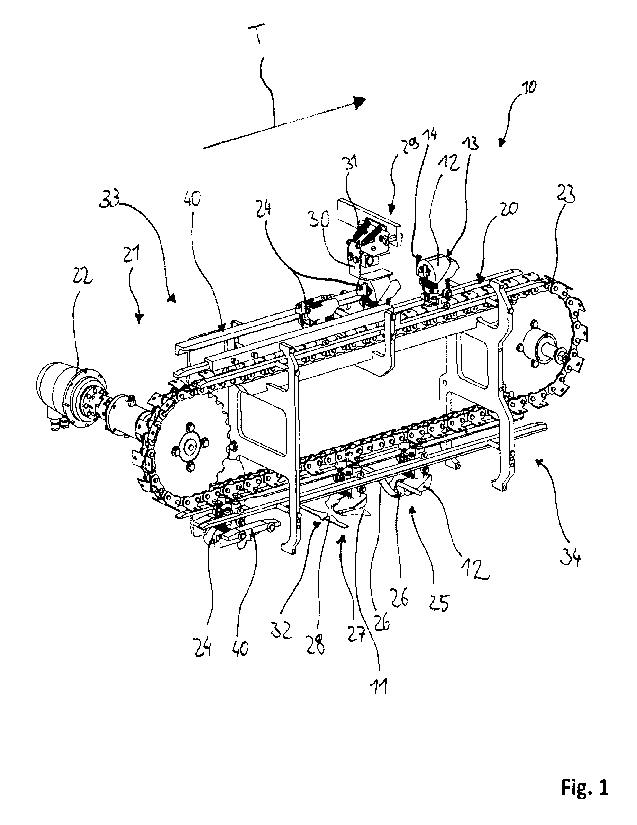
The apparatus 10 shown in Fig. 1 is configured and adapted for recovering back-
flesh
11 or parts thereof from back parts 12 or parts thereof of poultry carcasses -
not shown
in the figures - having a neck side 13 and a hip side 14 as well as a body
exterior side
15 and a body interior side 16, wherein the back part comprises a spinal
column 17 or
5 parts thereof and a rib structure 18 having at least vertebral rib pairs
19 or parts
thereof, and wherein the back-flesh 11 includes in particular at least one
scapula - not
shown in the figures -, which apparatus comprises a transport conveyor 21
which is
adapted for transporting the back parts 12 or parts thereof along a transport
path 20
with a centre axis M in a direction of transport T and which has a drive unit
22 and a
10 transport element 23 for conveying at least one holding element 24,
arranged on the
transport element 23, for receiving the back part 12 or parts thereof during
transport
along the transport path 20 at least in some regions; a first cutting means
assembly 25
which is arranged along the transport path 20 in the region of the transport
element 23
and which has at least one loosening means 26 for loosening the back-flesh 11
at least
15 in some regions substantially along the rib structure 18; a second
cutting means
assembly 27 which is arranged along the transport path 20 downstream of the
first
cutting means assembly 25 in the direction of transport T in the region of the
transport
element 23 and which has at least one separating knife 28 for separating the
cut back-
flesh 11 or parts thereof at least in some regions at least substantially
along the spinal
20 column 17, wherein the holding element 24 is so configured that the back
part 12 or
parts thereof can be arranged on the holding element 24 by non-positive and/or
positive locking engagement.
For better understanding of the invention, the anatomy of the back parts 12
having the
25 back-flesh 11 to be recovered which are to be arranged by means of the
at least one
holding element 24 will be described in detail with reference to Fig. 2.
Furthermore,
back parts 12 are shown in Fig. 1 and Fig. 4 during the operation of
positioning on
holding elements 24. The holding element 24 is configured and adapted in
particular for
the automatic or semi-automatic arrangement, positioning and fixing of the
back parts
30 12. In addition to the anatomical parts mentioned above, back parts 12
generally
further comprise at least one scapula - not shown in the figures - and at
least one skin
layer, which forms the outermost layer of the body exterior side 15. In the
present
figures, the back part 12 is shown only schematically and in a highly
simplified manner,
without depicting specific anatomical features of the above-mentioned parts in
detail.
35 The back part 12 is depicted in a simplified manner as a symmetrical
body part,
although natural products do not generally exhibit such perfectly matching
symmetries.
CA 03171953 2022- 9- 15
- 19 -
The back-flesh 11 located on the back part 12 is accessible predominantly via
the body
exterior side 15 and extends above the rib structure 18 and also in part above
the
spinal column 17. Fixing of the back part 12 on the holding elements 24
preferably
takes place only via engagement into the body interior side 16, the body
exterior side
5 15 is not in direct contact with the holding element 24. The skeletonised
region of the
back part 12 comprises especially the spinal column 17 and the ribs, the ribs
located in
the back part 12 generally being connected to the spinal column 17. The ribs
normally
occur as rib pairs 19, that is to say in each case two ribs extend along the
spinal
column 17 substantially symmetrically to one another, so that two ribs
opposite the
10 spinal column 17 in each case form a rib pair 19. All the ribs or rib
pairs 19 form the rib
structure 18. On the whole, the actual structure of the back part 12, that is
to say how
many rib pairs 19 the back part 12 comprises, is immaterial for the apparatus
10
according to the invention and for the use of the holding element 24, as long
as an
arrangement with the body interior side 16 with the holding element 24 is
possible and
15 provided that processing by means of the first cutting means assembly 25
and the
second cutting means assembly 27 can be carried out. Advantageously, however,
the
number of retaining teeth 35 on the holding element 24 corresponds to the
number of
rib pairs 19 or rib spaces. The at least one holding element 24 is configured
and
adapted so as to actively engage and fix the back part 12 from the body
interior side 16
20 in the region of the hip side 14, that is to say to engage the rib
structure 18 and/or the
part of the spinal column 17 located in that region, which is shown in
simplified form in
Fig. 4 during the pressing operation by means of the pressing device 29. In
simple
terms, the holding element 24 is so configured that it corresponds in shape to
the back
part 12 to be arranged thereon.
The features and further developments and also the method steps that are
described in
the following text represent preferred embodiments when considered alone or in
combination with one another. It is explicitly pointed out that features and
method steps
which are combined in the claims and/or the description and/or the drawing or
which
30 are described in a common embodiment can also further develop the
apparatus 10
described above and the method described below functionally independently.
As is apparent from Fig. 3, the back-flesh 11 can preferably at least
substantially only
be cut or loosened from the back part 12 by means of the first cutting means
assembly
35 25 and is not yet separated completely. The remaining part of the back-
flesh 11 which
has not yet been cut or loosened remains connected to the back part 12 and is
then
CA 03171953 2022- 9- 15
- 20 -
separated completely by means of the second cutting means assembly 27. Further
preferably, the separated back-flesh 11 can subsequently be processed further
on
apparatuses - which are not shown in the figures. As is shown in Fig. 1, 3, 4
and 5, a
plurality of holding elements 24 each having back parts 12 arranged thereon
are
5 particularly preferably arranged on the transport element 23 of the
transport conveyor
21 and guided continuously or discontinuously on the apparatus 10 through the
respective cutting means assemblies 25, 27. The first cutting means assembly
25
and/or the second cutting means assembly 27 in particular perform the cutting
operation in that the continuous transport of the back parts 12 on the
transport element
10 23 leads to the back part 12 coming up against a cutting edge 42 of the
respective
cutting means or knife, that is to say against the at least one loosening
means 26 and
against the at least one separating knife 28. The first cutting means assembly
25
and/or the second cutting means assembly 27, or the cutting means or knife
thereof,
are configured with their cutting edge preferably perpendicular to the
transport path 20
15 and are adjustable relative thereto.
The term transport path 20 refers to the path along the apparatus 10, on which
the
devices for processing or handling the back parts 12 are arranged or can be
arranged,
and ultimately describes a three-dimensional region over which the back parts
12 travel
20 or through which they pass as they are transported in the direction of
transport T.
When there is a device for processing or handling the back parts 12 in the
transport
path 20 of the back parts, for example the first cutting means assembly 25
having the
at least one loosening means 26 or the second cutting means assembly 27 having
the
at least one separating knife 28, the back part 12 is in engagement or
interacts
25 therewith as it passes. The direction of transport T represents the
course of the
transported holding elements 24 on the transport conveyor 21, and thus also
the
course of the respective guided back parts 12, whereby the respective
processing
steps on the back parts 12 are also defined. In the case of a continuous
course of the
transport path 20, as is shown for example in Fig. 1, the direction of
transport T
30 changes in the schematic illustration over the transport path 20 owing
to the division of
the apparatus 10 into an upper run 33 and a lower run 34.
There is preferably arranged upstream of the first cutting means assembly 25 a
pressing device 29 having a pressing element 30, which pressing device is
adapted to
35 press the received back part 12 on the holding element 24 from the body
exterior side
15 by means of the pressing element 30. Fig. 4 and Fig. 5 show the pressing
device 29
CA 03171953 2022- 9- 15
- 21 -
in each case with the pressing element 30. The pressing element 30 is thereby
in the
form of a planar element in order to ensure that pressing against the body
exterior side
15 of the back part 12 is as even as possible. The pressing element 30 can
also
correspond to the contour of the body exterior side 15 of the back part 12.
The pressing
device 29 can be resiliently mounted. In Fig. 4 and Fig. 5, the pressing
element 30 is
for this purpose provided with two tension springs 31, which leads to
consistent
pressing results. The pressing device 29 assists with the positioning of the
back part 12
on the holding element 24, and for this reason the pressing device 29, as is
shown in
Fig. 1, Fig. 4 and Fig. 5, is arranged in the region in which the back part 12
is received
- which is not shown in detail in the figures. The pressing element 30 of the
pressing
device 29 presses the back part 12 onto the holding element 24 after it has
been
received and holds the back part 12 at least temporarily in position on the
holding
element 24. Further preferably, pressing of the back part 12, or maintenance
of
pressing of the back part, by means of the pressing element 30 is to take
place at the
same time as closing and fixing of the holding element 24, or on engagement of
the
retaining teeth 35 into the rib-free regions of the back part 12.
Further preferably, the holding element 24 - shown in detail in Fig. 6 - is so
configured
that the back part 12 - shown in detail in Fig. 2 - can be arranged on the
holding
element 24 in the direction of transport T along the transport path 20 with
the neck side
13 in front. By arranging the back part with the neck side 13 in front, the
first cut into
the back part 12 by means of the at least one loosening means 26 of the first
cutting
means assembly 25 generally also takes place starting from the neck side 13.
During
the loosening process, the loosening means 26 then leave the back part 12 at
the hip
side 14.
The first cutting means assembly 25, in particular the at least one loosening
means 26,
is preferably configured so as to be deflectable against a spring force by
means of a
spring element - not shown in the figures. The spring element can thereby
preferably
be formed by a mechanical spring, for example a tension spring, although
pneumatic
solutions are also conceivable as an alternative. Furthermore, the first
cutting means
assembly 25 is further preferably formed by a pair of at least substantially
opposing
loosening means 26, wherein the loosening means 26 are arranged on either side
of
the transport path 20, such that, between the two loosening means 26 in the
region of
the centre axis M, a gap A is formed by the mutually opposing loosening means
26 for
avoiding the spinal column 17.
CA 03171953 2022- 9- 15
- 22 -
As is shown in Fig. 3, the loosening means 26 preferably have a curved shape
and are
configured to cut the back part 12 or parts thereof along the course of the
direction of
transport T starting from the neck side 15 and to leave the back part 12 or
parts thereof
5 again at the hip side 16, wherein the loosening means 26 loosen the back-
flesh 11
along the rib structure 18. The back-flesh 11 is loosened in that the
loosening means
26 completely loosen an extensive region of the back-flesh 11 above the rib
structure
18. However, the back-flesh 11 generally remains connected to the back part
12, or to
the remaining back-flesh 11, in the region of the spinal column 17. Further
preferably,
10 at least one of the loosening means 26 is adjustable in terms of height
relative to the
holding element 24 and/or in terms of distance from the centre axis M. The
loosening
means 26 are preferably fixedly arranged along the transport path 20, so that
the back
part 12 arranged on the holding element 24 is guided through the loosening
means 26,
whereby loosening takes place.
In the second cutting means assembly 27, the at least one separating knife 28
for
completely separating the back-flesh 11 is preferably configured and arranged
at least
substantially along the spinal column 17. For this purpose, the back part 12
arranged
on the holding elements 24 is guided along the transport path 20 and brought
into
20 engagement with the separating knife 28. In Fig. 3, the separating knife
28 is arranged
over the entire width of the transport path 20 so as to provide as complete a
separating
cut as possible of the back-flesh 11. The already loosened or cut back-flesh
11 is
separated by means of the separating knife 28 in that the separating knife 28
separates
the back-flesh 11 along the spinal column 17 and as close as possible thereto.
For this
25 purpose, the separating knife 28 is preferably fixedly arranged along
the transport path
20, so that the back part 12 arranged on the holding element 24 is guided
through the
separating knife 28, whereby separation takes place. The at least one
separating knife
28 is preferably configured and adapted so as to be adjustable in terms of
height
relative to the holding element 24.
The at least one separating knife 28 is preferably configured so as to be
deflectable
against a spring force by means of a spring element - not shown in the
figures. The
spring element can preferably be formed by a mechanical spring, for example a
tension
spring, although pneumatic solutions are also conceivable as an alternative.
It is
35 additionally apparent from Fig. 3 that the at least one separating knife
28 is
advantageously v-shaped or u-shaped 32. The v-shape or u-shape 32 thereby
CA 03171953 2022- 9- 15
- 23 -
corresponds substantially to the contour of the spinal column 17 of the back
part 12, so
as to separate the back-flesh 11 with minimal losses as the back part is
guided
through.
5 Fig. 1 shows that the transport conveyor 21 preferably has an upper run
33 and a lower
run 34, wherein the first cutting means assembly 25 and/or the second cutting
means
assembly 27 is arranged in the region of the lower run 34. In the course of
the lower
run 34, the back part 12 is guided on the holding element 24 generally in the
"upside-
down position", whereby the back-flesh 11 automatically falls down from the
back part
10 12 by means of gravity following the separating operation. The separated
back-flesh 11
can preferably be discharged via at least one discharge device - not shown in
the
figures - which is arranged along the transport path 20 in the direction of
transport T at
least in some regions and which is configured and adapted for discharging the
separated back-flesh 11 and/or the back part 12 or parts thereof freed of the
back-flesh
15 11, in particular beneath the first cutting means assembly 25 and/or
beneath the
second cutting means assembly 27. The discharge device for discharging the
back-
flesh 11 can further preferably be configured and arranged transversely in the
course of
the direction of transport T or along the direction of transport T.
20 The back part 12 or parts thereof can preferably be arranged with the
body interior side
16 on the holding element 24 by non-positive and/or positive locking
engagement, in
particular only in the region of the spinal column 17 and/or of the rib
structure 18 having
the rib pairs 19. For this purpose, the holding element 24 comprises, as is
shown in
Fig. 6, at least one retaining tooth 35 which is configured and adapted to be
in
25 operative connection by non-positive and/or positive locking engagement
with the back
part 12 in the region of the spinal column 17 and/or of the rib structure 18
having the rib
pairs 19. As is shown in Fig. 5, the holding element 24 can for this purpose
be
configured with the at least one retaining tooth 35 in a mounting position 39
and in a
clamping position 38. In the present figures, the holding element 24 in each
case
30 comprises four retaining teeth 35 arranged opposite one another, wherein
in the
mounting position 39 the retaining teeth 35 are open, that is to say the
opposing
retaining teeth 35 are spaced apart from one another, in order to receive a
back part 12
on the holding element 24 with the body interior side 16. In the clamping
position 38, as
is shown for example in Fig. 6, there is substantially no distance between the
retaining
35 teeth 35, whereby the spinal column 17 and/or the rib structure 19 is
retained.
CA 03171953 2022- 9- 15
- 24 -
The method will be described in greater detail in the following text.
The method serves and is suitable for recovering back-flesh 11 or parts
thereof from
back parts 12 or parts thereof, also referred to generally hereinbelow only as
back-flesh
5 11 and back parts 12, respectively, and is illustrated in Fig. 1. For
recovering the back-
flesh 11, the back parts 12 are first provided on a transport conveyor 21
which is
arranged along a transport path 20 with a centre axis M in a direction of
transport T and
which has a drive unit 22 and a transport element 23. The back parts 12 to be
conveyed are positioned by non-positive and/or positive locking engagement on
at
10 least one holding element 24 arranged on the transport element 23. For
this purpose,
the holding element 24 having the retaining teeth 35 is opened, in order that
the back
part 12 is arranged with the body interior side 16 therein, and is then fixed
on the one
hand to the spinal column 17 by means of the retaining teeth 35 by non-
positive locking
engagement and on the other hand by positive-locking engagement by the
15 engagement of the retaining teeth 35 into the rib-free region of the rib
structure 18. The
back part 12 is then transported in the direction of transport T along the
transport path
20 and the back part 12 is guided along the first cutting means assembly 25
which is
arranged along the transport path 20 in the region of the transport element 23
and
which has at least one loosening means 26. By means of the at least one
loosening
20 means 26, the back-flesh 11 is loosened at least substantially in some
regions along
the rib structure 18. By further transport of the back part 12 with the
loosened back-
flesh 11, a second cutting means assembly 27 which is arranged downstream of
the
first cutting means assembly 25 and which has at least one cutting knife 28
comes into
engagement with the back part 12, wherein the back-flesh 11 is separated at
least in
25 some regions at least substantially along the spinal column 17.
As is shown in Fig. 4, the back part 12, before, during and/or after
positioning by non-
positive and/or positive locking engagement on the holding element 24, is
preferably
pressed onto the holding element 24 from the body exterior side 15 by means of
a
30 pressing device 29 having a pressing element 30.
For practical changing between the operating positions of the holding element
24, that
is to say changing between the mounting position 39 and the clamping position
38, the
holding element 24 preferably comprises at least one trigger element 36,
wherein the
35 trigger element 36 is in operative connection with at least one of the
retaining teeth 35
such that the trigger element 36 effects a change from the mounting position
39 into
CA 03171953 2022- 9- 15
- 25 -
the clamping position 38. As is shown in Fig. 6, the holding element 24
preferably has a
trigger element 36 on each of two sides, which trigger elements can be in the
form of a
rod-shaped prolongation. The holding element 24 preferably further has at
least one
spring element 37 which is adapted so that it can be pretensioned under spring
loading
5 such that on activation of the trigger element 36 the holding element 24,
or at least one
of the retaining teeth 35, can be transferred into the mounting position 38
and on
deactivation of the trigger element 36 the holding element 24, or the at least
one
retaining tooth 35, can automatically be transferred into the clamping
position 38.
10 In the case of the holding elements 24 shown in the figures, activation
of the trigger
element 36 takes place in that the trigger element 36 is moved in the course
of a
pivoting movement, wherein force that is greater than the force of the spring
element
37 is applied to the trigger element 36. The application of force can in
principle take
place in any desired way. As a result of the application of force, a change
from the
15 clamping position 38 into the mounting position 39 takes place.
The apparatus 10 preferably comprises at least one engagement element 40 which
is
configured and adapted to act together with the trigger element 36 of the
holding
element 24 in order to effect a change between the mounting position 39 and
the
20 clamping position 38 of the at least one retaining tooth 35. In Fig. 1
and Fig. 4, the
engagement element 40 is shown as continuous path control, also called cam
track, in
which the trigger element 36 can be guided at least in part, whereby the
application of
force for activating the trigger element 36 takes place by changing the
guiding of the
trigger element 36 in that the trigger element 36 is forcibly guided in the
engagement
25 element 40 by the forward movement of the holding element 24. Depending
on the
profile of the continuous path control of the engagement element 40, control
of the
engagement element 40 with the trigger element 36 can thus take place as
required.
For convenient guiding of the trigger element 36 in the engagement element 40,
the
trigger element 36 is configured with a running wheel 41 which can be guided
in the
30 engagement element 40, whereby the application of force can be
transferred to the
trigger element 36. In this manner, the trigger element 36 in each case allows
the
retaining teeth 35, or the holding element 24, to change between the mounting
position
39 and the clamping position 38.
35 In addition, an engagement element 40 can preferably be arranged after
the second
cutting means assembly 27 in order to remove the back part 12 separated from
the
CA 03171953 2022- 9- 15
- 26 -
back-flesh 11 from the holding element 24, so as to mount a further back part
12 in the
further course, whereby continuous operation of the apparatus 10 for
recovering back-
flesh 11 is ensured.
The method is particularly preferably carried out with an apparatus 10
according to one
or more of claims 1 to 15, as have been described above in various
embodiments.
CA 03171953 2022- 9- 15