Note: Descriptions are shown in the official language in which they were submitted.
CA 03172350 2022-08-22
WO 2021/181077 PCT/GB2021/050577
1
DELIVERY CONSUMABLE FOR DELIVERING A FLUID TO A BIOREACTOR
[0001] This invention relates to a delivery consumable for delivering a fluid
to a bioreactor.
The bioreactor is suitable for performing one or more unit operations in a
cell processing
method, for example, in cell and/or gene therapy manufacturing processing. The
fluid
delivery consumable is operable to transfer a fluid from the fluid delivery
consumable to
the bioreactor.
BACKGROUND
[0002] Cell and gene therapy manufacturing processes are often complex and
include
manual or semi-automated steps across several devices. Equipment systems used
in
various steps, or unit operations, of cell-based therapeutic products (CTP)
manufacturing
may include devices for various functions. These various functions may be, for
example,
cell collection, cell isolation, cell selection, cell expansion, cell washing,
volume reduction,
cell storage or transportation. The unit operations can vary immensely based
on the
manufacturing model (i.e. autologous versus allogenic), cell type, intended
purpose,
among other factors. In addition, cells are "living" entities sensitive to
even the simplest
manipulations, for example, such as differences in a cell transferring
procedure. The role
of cell manufacturing equipment in ensuring scalability and reproducibility is
an important
factor for cell and gene therapy manufacturing.
[0003] In addition, cell-based therapeutic products (CTP) have gained
significant
momentum thus there is a need for improved cell manufacturing equipment for
various cell
manufacturing procedures. These manufacturing procedures, may include, for
example,
stem cell enrichment, generation of chimeric antigen receptor (CAR) T cells,
and various
cell manufacturing processes such as collection, purification, gene
modification,
incubation, recovery, washing, infusion into a patient, or freezing.
[0004] The culture or processing of cells typically requires the use of a
device to hold the
cells, for example in an appropriate culture medium when culturing the cells.
The known
devices include shaker flasks, roller bottles, T-flasks, bags and the like.
Such devices are
typically required to be connected to other devices, such as containers,
interfaces or the
like, so that various media may be introduced to, or removed from, the device
holding the
cells. Typically, cells in a culture medium can be added to the device from a
flexible bag
that is attached using a connecting tube. Alternatively, cells can be
transferred by a pipette
or by a syringe.
[0005] The production of autologous CAR T cells is carried out by a variety of
manufacturing approaches all comprising the same common steps. First, the
patient's
white blood cells (VVBCs) are isolated by leukapheresis and washed. Then, the
T cells are
CA 03172350 2022-08-22
WO 2021/181077 PCT/GB2021/050577
2
activated, transduced with the CAR transgene, expanded to the required cell
numbers for
therapy, formulated and filled. After quality control testing and preparatory
lymphodepleting
chemotherapy for the patient, the product is injected into the patient.
BRIEF SUMMARY OF THE DISCLOSURE
[0006] In accordance with the present disclosure there is provided a delivery
consumable
for delivering a fluid to a bioreactor, the delivery consumable comprising:
a container having:
a collapsible portion comprising a collapsible wall; and
an intermediate portion connected to the collapsible portion and being
adapted to hold a fluid, and
a connector for connecting the intermediate portion to the bioreactor,
wherein during use the collapsible portion is collapsible so as to urge the
fluid
through the connector and into the bioreactor.
[0007] In examples, the collapsible portion may comprise a frustrum-shaped
collapsible
wall extending from a first end at the intermediate portion to a second end of
the
collapsible portion opposite to the first end, the first end being larger than
the second end.
The frustrum-shaped collapsible wall may be a frustoconical collapsible wall.
In examples,
the second end of the frustrum-shaped collapsible wall is connected to the
intermediate
portion.
.. [0008] In examples, the second end of the collapsible portion may comprise
a cap.
[0009] In examples, the collapsible portion may further comprise a second
frustrum-
shaped collapsible wall extending from a second end to a first end, the first
end being
larger than the second end, and wherein the second end of the second frustrum-
shaped
collapsible wall is joined to the second end of the frustrum-shaped
collapsible wall. The
.. second frustrum-shaped collapsible wall may be a second frustoconical
collapsible wall. In
examples, the first end of second frustrum-shaped collapsible wall may
comprise a cap.
[0010] In examples, the collapsible portion may be configured to hold at least
a part of the
fluid.
[0011] In examples, the delivery consumable may further comprising a divider
between
the intermediate portion and the collapsible portion. The divider may comprise
a valve. In
examples, the intermediate portion may be configured to hold the entire fluid
provided to
the delivery consumable. In examples, the valve may be a two-way valve.
CA 03172350 2022-08-22
WO 2021/181077 PCT/GB2021/050577
3
[0012] In examples, the collapsible wall may comprise a bellows wall. In
examples, the
bellows wall may comprise a plurality of inward folds and a plurality of
outward folds
arranged alternately between opposing ends of the collapsible wall.
[0013] In examples, the collapsible wall may comprise a silicone or a
thermoelastic
polymer, for example a polyvinyl chloride. In other examples, the collapsible
wall may
comprise a low density polyethylene. In examples, a surface of the collapsible
wall may
comprise a coating, for example an outer surface of the collapsible wall may
comprise a
coating. Additionally or alternatively, an inner surface of the collapsible
wall may comprise
a coating. In examples, the coating is gas-impermeable.
[0014] In examples, the connector comprises a seal arranged to seal an end of
the
intermediate portion. The connector may be actuatable to open or break the
seal and
create a fluid connection from the intermediate portion through the connector.
In examples,
the connector may comprise a needle actuatable to pierce the seal. In
examples, the seal
may comprise a septum seal.
[0015] In examples, the delivery consumable may further comprise a feed tube
in fluid
communication with the intermediate portion. In examples, the intermediate
portion may
comprise an external spigot for attachment of the feed tube. In examples, the
feed tube
may be closable, for example crimpable or weldable, so as to seal the feed
tube after a
fluid has been added to the delivery consumable.
[0016] In examples, the delivery consumable may be a cell delivery consumable
and the
fluid may be a cell suspension. In examples, the delivery consumable may be a
media
delivery consumable and the fluid may be a medium, for example a cell
culturing medium.
[0017] In examples, the delivery consumable further comprises a fluid in the
container, for
example a cell suspension or a medium.
[0018] In accordance with the present disclosure there is provided a method of
delivering
a fluid to a bioreactor, the method comprising: filling the delivery
consumable described
above with a fluid, connecting the delivery consumable to the bioreactor via
the connector
of the delivery consumable; and at least partially collapsing the collapsible
portion of the
delivery consumable to transfer the fluid into the bioreactor.
BRIEF DESCRIPTION OF THE DRAWINGS
[0019] Embodiments of the invention are further described hereinafter with
reference to
the accompanying drawings, in which:
FIG. 1 shows a cell processing system that includes a bioreactor;
FIG. 2 schematically illustrates a cell culturing process;
CA 03172350 2022-08-22
WO 2021/181077 PCT/GB2021/050577
4
FIG. 3 illustrates the bioreactor;
FIGS. 4A and 4B show an example of a fluid delivery consumable attaching to
the
bioreactor;
FIG. 5 shows an example connector for connecting the fluid delivery consumable
to
the bioreactor;
FIG. 6 shows an example fluid delivery consumable;
FIGS. 7A and 7B show cross-sectional views of the fluid delivery consumable of
FIG. 6;
FIGS. 8A and 8B show example fluid delivery consumables with different
volumes;
FIG. 9 shows a further example fluid delivery consumable;
FIG. 10 shows a cross-section of the fluid delivery consumable of FIG. 9;
FIG. 11 shows a cross-section of the fluid delivery consumable of FIG. 9 in a
partially collapsed state; and
FIGS. 12A and 12B illustrate a further example fluid delivery consumable;
FIGS. 13A to 13E illustrate a method of delivering a fluid to the bioreactor
using a
fluid delivery consumable.
DETAILED DESCRIPTION
[0020] FIG. 1 shows a cell processing system 1 that includes a cell processing
housing 2,
a cell processing platform 3, a bioreactor 4, and various accessories, for
example,
"consumables" 5a-5f.
[0021] The cell processing housing 2 provides a closed environment for the
cell
processing platform 3 and is provided with power, connectivity and other
utilities needed
for the cell processing as described hereinafter. The cell processing platform
3 is adapted
to receive the bioreactor 4 and support the bioreactor 4 within the cell
processing housing
2. The cell processing platform 3 may include various components and systems
that
interact with the bioreactor 4 and/or the consumables 5a-5f. For example, the
cell
processing platform 3 may include an agitator that acts to agitate the
bioreactor 4 so as to
agitate a cell suspension provided within the bioreactor 4. In other examples,
the cell
processing platform 3 may include an accessory support arm adapted to hold one
or more
consumables 5a-5f. In examples, the cell processing platform 3 may include an
actuator
operable to actuate one or more the consumables 5a-5f. The cell processing
platform 3
may be configured for automated operation of the cell processing system 1, or
may permit
manual operation.
CA 03172350 2022-08-22
WO 2021/181077 PCT/GB2021/050577
[0022] The bioreactor 4, described in more detail with reference to FIG. 3,
includes a
container 12 and an interface plate 13. During use the container 12 holds a
fluid in which
the cell processing occurs. In particular, the fluid comprises a population of
cells present in
a liquid medium. The container 12 may be expandable, for example by having a
bellows
5 wall. The bioreactor 4 is held in the cell processing housing 2 such that
the container 12
can expand and retract as it is filled and emptied. The interface plate 13 may
be engaged
by the cell processing platform 3 and provides various functions relating to
the bioreactor
4. For example, the interface plate 13 may have one or more connectors for
transfer of
fluids into and out of the container 12.
[0023] The consumables 5a-5f are for connecting to the bioreactor 3,
optionally via the cell
processing platform 3, in order to facilitate process steps of the cell
culturing process.
[0024] In examples, a cell delivery consumable 5a is provided. The cell
delivery
consumable 5a is adapted to connect to the bioreactor 4 and deliver a cell
suspension to
the bioreactor 4. In particular, the cell delivery consumable 5a has a
container that is filled
with a cell suspension, and a connector that connects to the bioreactor 4
(optionally via the
cell processing platform 3). The cell delivery consumable 5a is operable to
transfer the cell
suspension from the cell delivery consumable 5a into the bioreactor 4. The
cell suspension
may include "live" cells and a medium. Accordingly, the cell delivery
consumable 5a
delivers the cell suspension to a bioreactor 4.
[0025] The population of cells may comprise any cell type. Suitably the
population of cells
may comprise a homogenous population of cells. Alternatively the population of
cells may
comprise a mixed population of cells.
[0026] The population of cells may comprise any human or animal cell type, for
example:
any type of adult stem cell or primary cell, T cells, CAR-T cells, monocytes,
leukocytes,
erythrocytes, NK cells, gamma delta t cells, tumour infiltrating t cells,
mesenchymal stem
cells, embryonic stem cells, induced pluripotent stem cells, adipose derived
stem cells,
Chinese hamster ovary cells, NSO mouse myeloma cells, HELA cells, fibroblasts,
HEK
cells, insect cells, organoids etc. Suitably the population of cells may
comprise T-cells.
[0027] Alternatively, the population of cells may comprise any microorganism
cell type, for
.. example: bacterial, fungal, Archaean, protozoan, algal cells.
[0028] In examples, a bead loading consumable 5b is provided. The bead loading
consumable 5b may hold a bead suspension, for example a suspension of magnetic
beads
in water. The bead loading consumable 5b is operable to deliver the beads to
the
bioreactor 4. The magnetic beads may be used in a cell selection process.
CA 03172350 2022-08-22
WO 2021/181077 PCT/GB2021/050577
6
[0029] In examples, the bead loading consumable 5b may alternatively or
additionally be a
virus loading consumable 5b. The virus loading consumable 5b may hold a virus
solution
or suspension for delivery to the bioreactor 4.
[0030] In examples, a media delivery consumable 5c may be provided. The media
delivery
.. consumable 5c may comprise a container that is filled with one or more
media, for
example a cell culturing medium, and a connector that connects to the
bioreactor 4. The
media delivery consumable 5c is operable to move the medium into the
bioreactor. In
examples, the media delivery consumable 5c is collapsible, similar to the cell
delivery
consumable 5a. The medium may be a liquid.
[0031] In examples, the liquid medium may be any sterile liquid capable of
maintaining
cells. The liquid medium may be selected from: saline or may be a cell culture
medium.
The liquid medium may be a cell culture medium selected from any suitable
medium, for
example: DMEM, XVIVO 15, TexMACS. The liquid medium may be appropriate for the
type of cells present in the population. For example, the population of cells
comprises T
cells and the liquid medium comprises XVIVO 10.
[0032] In examples, the liquid medium may further comprise additives, for
example:
growth factors, nutrients, buffers, minerals, stimulants, stabilisers or the
like.
[0033] In examples, the liquid medium comprises growth factors such as
cytokines and/or
chemokines. The growth factors may be appropriate for the type of cells
present in the
population and the desired process to be carried out. The liquid medium may
comprise
stimulants such as antigens or antibodies, which may be mounted on a support.
Suitable
stimulants are appropriate for the type of cells present in the population and
the desired
process to be carried out. When culturing T-cells, for example, antibodies are
provided as
a stimulant in the liquid medium. The antibodies may be mounted on an inert
support such
as beads, for example: dynabeads.
[0034] The additives may be present in the liquid medium at an effective
concentration. An
effective concentration can be determined by the skilled person on the basis
of the
population of cells and the desired process to be carried out using known
teachings and
techniques in the art.
[0035] In examples, the population of cells are seeded in the liquid medium at
a
concentration of between 1x10⁴ cfu/ml up to 1x10⁸cfu/ml.
[0036] In examples, a sampling consumable 5d may be provided. The sampling
consumable 5d may comprise a sampling vial. In examples, the sampling
consumable 5d
may comprise a vacutainer.
CA 03172350 2022-08-22
WO 2021/181077 PCT/GB2021/050577
7
[0037] In examples, a waste consumable 5e may be provided. The waste
consumable 5e
may comprise a container, for example an expandable container, adapted to
receive a
waste material removed from the bioreactor 4. The waste consumable 5e may
include a
filter arranged to filter the cells and/or other media from the fluid within
the bioreactor so as
only to extract the waste components.
[0038] In examples, a cell harvesting consumable 5f may be provided. The cell
harvesting
consumable 5f may comprise a container, for example an expandable container,
adapted
to receive the cells (and optionally a cell medium) at or towards the end of
the cell culturing
process. The cell harvesting consumable 5f may include a filter arranged to
filter a waste
component from the cells and/or other media within the bioreactor so as only
to extract the
cells and desired media.
[0039] In examples, each of the consumables 5a-5f is connectable to the
bioreactor 4 by a
common connector. The connector may be that described in applicant's co-
pending patent
application PCT/GB2020/053229, as described further with reference to FIG. 5.
[0040] The connector can be connected to the consumable 5a-5f, or may be an
integral
part of the consumable 5a-5f. Operation of the connector, for example by
twisting or
sliding, moves a needle so as to create a fluid connection between each end of
the
connector. Accordingly, the connector allows each consumable 5a-5f to be
connected to
the bioreactor 4, and then actuation of the connector forms a fluid connection
between the
consumable 5a-5f and the bioreactor 4 for transfer of materials as set out
above. As
explained further below, the connectors ensures sterility of the bioreactor 4
and the
consumable 5 while creating a fluid connection between the two.
[0041] FIG. 2 schematically illustrates a cell culturing process 6 based on
the cell
processing system 1 described with reference to FIG. 1. As shown in FIG. 2,
initially the
consumables 5a-5f are prepared 7. For example, a cell delivery consumable 5a
may be
filled with a cell suspension, and a virus loading consumable 5b may be filled
with a virus
suspension. A connector may be attached to the consumable 5a-5f before or
after
preparation. Preparation of the consumable(s) 5a-5f may include unpackaging
the
consumable(s) 5a-5f from a sterile package. It will be appreciated that only
the
consumables 5a-5f needed for the particular process, and the particular stage
of the
process, are prepared. For example, some processes would not use beads so a
bead
loading consumable 5b is not needed, and the cell harvesting consumable 5f is
only
needed at the end of the process 6.
[0042] Next, cells are loaded into the bioreactor 4, 8. In particular, a cell
delivery
consumable 5a is connected to the bioreactor 4 and operated to transfer a cell
suspension
from the cell delivery consumable 5a into the bioreactor 4. The cell delivery
consumable 5a
CA 03172350 2022-08-22
WO 2021/181077 PCT/GB2021/050577
8
is connected to the bioreactor 4 via a connector, as described above, which
forms a fluid
connection between the cell delivery consumable 5a and the bioreactor 4.
[0043] Either before or after loading cells into the bioreactor 4, 8, the
bioreactor 4 is
loaded into the cell processing housing 2, 9. In some examples, the bioreactor
4 is
attached to the cell processing platform 3 within the cell processing housing
2.
[0044] Within the cell processing housing 2 the cells are processed 10 in the
bioreactor 4.
During processing 10 the pressure, temperature, pH and other environmental
characteristics within the bioreactor 4 are controlled to ensure that
conditions enable cell
processing. Cell processing 10 may comprise reprogramming the cells, for
example by
using CAR-coding viral DNA. Cell processing 10 may comprise cell culturing.
[0045] During cell processing 10 additional consumables 5a-5f may be used to
add
materials to the bioreactor 4, to extract a sample from the bioreactor 4,
and/or to extract
waste from the bioreactor 4. For example, a bead loading consumable 5b may be
used to
add magnetic beads to the bioreactor. In examples, a virus loading consumable
5b may be
used to add a virus suspension or solution to the bioreactor (e.g., CAR-coding
viral DNA).
In examples, a media delivery consumable 5c may be used to add one or more
media to
the bioreactor 4. For example, a media delivery consumable 5c may be used to
add a
balanced salt solution or a basal media to the bioreactor 4. In examples, a
sampling
consumable 5d may be used to extract a sample from the bioreactor for testing.
In
examples, during or after cell processing 10 a waste consumable 5e may be used
to
extract a waste media from the bioreactor 4.
[0046] After cell processing 10 the cells are harvested 11. Cell harvesting 11
may initially
use a waste consumable 5e to extract a waste component. A harvesting
consumable 5f
can be attached to bioreactor 4 to receive the cells from the bioreactor 4.
The cells may be
harvested in a media, for example a cell suspension may be harvested.
[0047] As shown in FIG. 3, the bioreactor 4 comprises a container 12 and an
interface
plate 13. The interface plate 13 comprises at least one connector interface 21
for
connecting to an external component, for example one of the consumables 5a-5f
described above. In examples, the connector interface 21 includes a septum
seal that
maintains a sealed environment within the container 12 and also permits a
needle to pass
through to create a fluid connection into the container 12.
[0048] The container 12 is a collapsible container. In particular, the
container 12 has a
bottom wall 15 disposed opposite to the interface plate 13, and a collapsible
wall 16
defining a sidewall of the container 12. A top part 17 of the collapsible wall
16 is attached
to the interface plate 13. The top part 17 may include a rigid ring or similar
for attaching to
CA 03172350 2022-08-22
WO 2021/181077 PCT/GB2021/050577
9
the interface plate 13. The collapsible wall 16 is collapsible such that the
bottom wall 15
can move towards and away from the interface plate 13, changing the internal
volume of
the container 12.
[0049] The collapsible wall 23 may be a bellows wall, having a concertina
arrangement
that allows the collapsible wall 23 to fold onto itself in order to collapse.
In particular, the
collapsible wall 23 may comprise a series of alternately arranged inward folds
16a and
outward folds 16b that allow the collapsible wall 23 to collapse like a
bellows or concertina.
The inward folds 16a and outward folds 16b may be formed by thinned sections
in the
collapsible wall 23, with the inward folds 16a comprise a thinned section
arranged on the
outer surface of the collapsible wall 23, and the outward folds 16b comprising
a thinned
section arranged on the inner surface of the collapsible wall 23.
[0050] In other examples, the container 12 may be formed by sealed and
telescopically
arranged rings permitting the container 12 to elongate and shorten to change
an internal
volume of the container 12. In other examples, the container 12 may be made
from a
flexible or extendible material, for example a resiliently flexible material,
allowing the
container 12 to expand and contract.
[0051] The container 12 can therefore expand and contract, or be expanded and
contracted, according to the material held in the container 12 and/or an
external force. In
particular, the collapsible container 12 may expand as the cell culture within
the container
12 grows, and/or as additional materials are added. The cell processing
housing (2, see
FIG. 1) may comprise an actuator adapted to move, for example push and/or
pull, the
bottom wall 15 of the container 12 and/or the interface plate 13 to change the
volume of
the container 12.
[0052] As illustrated, the interface plate 13 also includes an expansion
container 14,
otherwise called a breathing container. The expansion container 14 allows for
the
container 12 to expand and contract without greatly changing the pressure in
the container
12. Alternatively or additionally, the expansion container 14 may be operable,
for example
by being mechanically or manually compressed or expanded, to expand or retract
the
collapsible wall 16 of the container 12 and thereby change a volume of the
container 12.
Alternatively or additionally, the expansion container 14 may be operable, for
example by
being mechanically or manually compressed or expanded, to alter the pressure
within the
container 12.
[0053] FIGS. 4A and 4B illustrate an example of connecting a consumable to the
bioreactor 4 of FIG. 3, for example a cell delivery consumable 5a or a media
delivery
consumable Sc.
CA 03172350 2022-08-22
WO 2021/181077 PCT/GB2021/050577
[0054] As shown, the consumable 5a, 5c has a container 18 and a connector 19.
The
container 18 comprises a collapsible wall 20. The collapsible wall 20 may be
similar to the
collapsible wall 16 of the container 12 of the bioreactor 4 illustrated in
FIG. 3. In particular,
the collapsible wall 20 comprises a series of alternating inward and outward
folds that
5 allow the collapsible wall 20 to collapse. The container 18 is filled
with a fluid, for example
a cell suspension or cell culturing media, which has expanded the collapsible
wall 20 to an
extended state, as illustrated. In some examples, the container 18 comprises
the
connector 19, and in other examples the container 18 is attached to the
connector 19, for
example by a threaded connection as illustrated further in FIG. 5.
10 [0055] As shown in FIG. 4B, the connector 19 is connected to the
interface plate 13 of the
bioreactor 4, in particular to a connector interface 21 of the interface plate
13. In examples,
the connector interface 13 comprises a seal, for example a septum seal, that
seals the
bioreactor 4. The connector 19 is actuatable, as described with reference to
FIG. 5, to form
a fluid connection between the container 18 of the consumable 5a, 5b and the
container 12
of the bioreactor 4. In examples, the connector 19 comprises a needle that is
moved when
the connector 19 is actuated in order to pierce the seal of the connector
interface 21 and
form a fluid connection with the bioreactor.
[0056] Once the fluid connection is established the fluid is transferred from
the container
18 of the consumable 5a, 5b to the container 12 of the bioreactor 4. The fluid
may be
transferred by gravity. In particular, gravity will act to compress the
container 18 by folding
the collapsible wall 20, thereby urging the fluid through the fluid
connection. Alternatively or
additionally, the container 18 of the consumable 5a, 5b may be compressed,
either
manually by an operator or by an actuator of the cell processing system (1,
see FIG. 1).
Compressing the container 18 of the consumable 5a, Sc urges the fluid through
the fluid
connection and into the container 12 of the bioreactor 4.
[0057] Once the fluid has been transferred from the consumable 5a, Sc to the
bioreactor 4
the consumable 5a, Sc can be detached from the bioreactor 4. On detaching the
connector
19 from the connector interface 21 the seal of the connector interface 21 may
reseal the
connector interface 21. For example, the seal of the connector interface 21
may be a
septum seal that reseals on withdrawal of the needle.
[0058] FIG. 5 illustrates the connector 19. The connector 19 is used to attach
a
consumable 5a-5f to the bioreactor 4, in particular to the connector interface
21 of the
interface plate 13 of the bioreactor 4. The connector 19 may be as described
in the
applicant's patent application PCT/GB2020/053229.
[0059] In particular, as shown in FIG. 5 the connector 19 comprises a housing
102 having
an upper housing portion 102a and a lower housing portion 102b. The housing
102
CA 03172350 2022-08-22
WO 2021/181077 PCT/GB2021/050577
11
extends along a longitudinal axis between a distal end 104 and a proximal end
106. The
upper housing portion 102a may be axially moveable, or slidable, with respect
to the lower
housing portion 102b, as will be described further below.
[0060] The housing 102 includes a threaded portion 107 at its distal end 104
for
.. connecting to a corresponding threaded portion of the container (18, see
FIG. 4A) of the
consumable (e.g., the cell delivery consumable 5a, see FIG. 4A). The threaded
portion 107
is formed on the upper housing portion 102a. As will be clear to the skilled
person, the
housing 102 may be provided without the threaded portion 107, and instead be
provided
with another suitable connection mechanism for connecting to a portion of the
container
(18, see FIG. 4A).
[0061] The connector 19 also includes a connector portion at its proximal end
106 for
connecting to the bioreactor (4, see FIG. 3), in particular a connector
interface (21, see
FIG. 4B) of the bioreactor 4. The connector portion may be a groove 138, as
illustrated in
FIG. 5, configured to receive one or more protrusions or legs on the
bioreactor.
Alternatively, the connector 19 may comprise a threaded portion or other
connector portion
for connecting to the bioreactor.
[0062] In this embodiment, the connector 19 includes a first septum seal 108
disposed at
the distal end 104 of the housing 102, and a second septum seal 110 disposed
at the
proximal end 106 of the housing 102. The first septum seal 108 includes a
substantially
planar, i.e. flat, pierceable surface facing outwardly at the distal end 104.
The second
septum seal 110 includes a generally annular portion, extending outwardly at
the proximal
end 106, enclosing a substantially planar, i.e. flat, pierceable surface
facing outwardly at
the proximal end 106. The housing 102 further includes a hollow needle 112
that is
biasedly mounted within the housing 102. The hollow needle 112 is generally
coaxially
aligned with the longitudinal axis. The hollow needle 112 includes a first end
114, facing
the first septum seal 108, and a second end 116, facing the second septum seal
110. The
first end 114 is configured to be able to pierce the first septum seal 108, in
use, and the
second end 116 is configured to be able to pierce the second septum seal 110,
in use. The
first septum seal 108, the second septum seal 110, or both the first and
second septum
seal 108, 110 may optionally be provided with a removable aseptic paper seal
111.
[0063] The hollow needle 112 is mounted within the housing 102 through a
collar 118 that
is spring-biased by a first helical spring 120 and a second helical spring
122. In other
embodiments, the hollow needle 112 may be mounted in another suitable manner,
for
example, the hollow needle 112 may be statically mounted, i.e. such that it
does not move,
and the housing 102 may be moveable about the hollow needle 112. The first
spring 120
acts between the distal end 104 of the housing 102 and the collar 118. The
second spring
CA 03172350 2022-08-22
WO 2021/181077 PCT/GB2021/050577
12
122 acts between the proximal end 106 of the housing 102 and the collar 118.
In this way,
the first spring 120 provides a first biasing force to the hollow needle 112,
via the collar
118, in a direction towards the proximal end 106 of the housing 102, and the
second spring
122 provides a second biasing force to the hollow needle 112, via the collar
118, in a
direction towards the distal end 104 of the housing 102.
[0064] The connector 19 further includes an actuating mechanism for causing
the hollow
needle 112 to pierce the septum seals 108, 110. By piercing the first and
second septum
seals 108, 110 the hollow needle 112 creates a fluid path between the distal
end 104 and
the proximal end 106 of the connector 19, and so during use creates a fluid
connection
between the container 18 of the consumable (e.g., the cell delivery consumable
5a or
media delivery consumable 5c, see FIG. 1) and the container 12 of the
bioreactor 4, as
shown in FIG. 4B.
[0065] In the example illustrated in FIG. 5 the actuating mechanism includes
an outer
sleeve 134 that is arranged to collapse the upper housing portion 102a with
respect to the
lower housing portion 102b. The outer sleeve 134 is rotatable with respect to
the housing
102 about the central longitudinal axis of the housing 102. For example, one
of the outer
sleeve 134 and the housing 102 may include a helical groove, and the other of
the outer
sleeve 134 and housing 102 may include a protrusion that engages the groove
such that
when the upper housing portion 102a collapses with respect to the lower
housing portion
102b the outer sleeve 134 is rotated.
[0066] When the connector 19 is attached to the container (18, see FIG. 4A),
in particular
via the threaded portion 107, the first septum seal 108 seals the end of the
container (18,
see FIG. 4A). The proximal end 106 of the connector 19 is then attached to the
connector
interface (21, see FIG. 4B), for example by a clipping mechanism, a sliding
mechanism, a
threaded connection, or clamping. In this position, actuation of the actuating
mechanism, in
particular rotation of the outer sleeve 134, causes the upper housing portion
102a to
collapse with respect to the lower housing portion 102b and the hollow needle
112 pierces
the first septum seal 108 and the second septum seal 110 and creates a fluid
connection
through the connector 19, between the container (18, see FIG. 4A) and the
bioreactor (4,
see FIG. 4B).
[0067] Accordingly, the connector 19 initially provides a sealing closure for
the container
(18, see FIG. 4A), and the fluid connection is formed entirely within the
connector 19,
which advantageously maintains a sterile environment.
[0068] Once the fluid has been transferred from the consumable to the
bioreactor (4, see
FIG. 4B) (or vice versa) through the hollow needle 112, the actuation
mechanism can be
reversed so that the needle withdraws from the first septum seal 108 and
optionally also
CA 03172350 2022-08-22
WO 2021/181077 PCT/GB2021/050577
13
the second septum seal 110. The first and/or second septum seal 108, 110
reseal on
withdrawal of the hollow needle 112. The connector 19, and the container (18,
see FIG.
4A), can then be detached from the bioreactor (4, see FIG. 4B).
[0069] In examples, an end of the container 18 of the consumable 5a, 5b
illustrated in FIG.
4A comprises a plug seal, for example a septum seal, so that the container 18
is sealed
before the connector 19 is connected. The plug seal of the container 18 can be
pierced by
the hollow needle 112.
[0070] In examples, the connector interface 21 of the bioreactor 4 illustrated
in FIGS. 3
and 4B comprises a further septum seal that is pierced by the hollow needle
112 in use.
Accordingly, when the connector 19 is detached the bioreactor 4 remains
sealed.
[0071] FIGS. 6 to 8B illustrate a first example delivery consumable 5a, 5c,
for example a
cell delivery consumable 5a or a media delivery consumable 5c. As shown in
FIG. 6, the
delivery consumable 5a, 5c comprises a collapsible portion 22, a connector 19,
and an
intermediate portion 24. The intermediate portion 24 is arranged between the
collapsible
portion 22 and the connector 19.
[0072] The connector 19, described with reference to FIG. 5, may be attached
to the
intermediate portion 24, for example via a threaded connection (see threaded
portion 107
in FIG. 5). In other examples, the connector 19 may be integral with the
intermediate
portion 24.
[0073] The connector 19 is connectable to the bioreactor (4, see FIG. 3), in
particular to
the connector interface (21, see FIG. 3) of the bioreactor 4, as previously
described. As
described with reference to FIG. 5, after the connector 19 has been attached
to the
bioreactor 4 it can be actuated to create a fluid connection between the
delivery
consumable 5a, Sc and the bioreactor 4. After the fluid connection is formed
by the
connector 19 the collapsible portion 22 can be collapsed to urge the fluid
into the
bioreactor 4.
[0074] In other examples the connector of the delivery consumable 5a, Sc may
comprise
an openable valve, a breakable seal, or other sealing mechanism that initially
seals the
delivery consumable 5a, Sc and is openable once the connector is connected to
the
bioreactor to provide a fluid connection between the delivery consumable 5a,
Sc and the
bioreactor.
[0075] The fluid provided to the delivery consumable 5a, Sc may be received in
the
intermediate portion 24. In examples, all of the fluid provided to the
delivery consumable
5a, 5b is received in the intermediate portion 24. This is particularly
advantageous where
the fluid is a cell suspension and the delivery consumable is a cell delivery
consumable 5a,
CA 03172350 2022-08-22
WO 2021/181077 PCT/GB2021/050577
14
as the cells are valuable and delicate and it may be beneficial to prevent
them from
contacting the collapsible portion 22.
[0076] As shown in FIG. 6, the intermediate portion 24 comprises a container
portion and
a funnel portion 25. The intermediate portion 24 defines an internal volume in
which the
fluid is held. The intermediate portion 24 may be transparent so that a user
can see the
fluid in the delivery consumable 5aõ 5c, and can see that the fluid has been
transferred to
the bioreactor after use. The intermediate portion 24 may comprise volume
markings to
indicate the volume of fluid in the delivery consumable 5a, 5c.
[0077] The connector 19 is disposed at an end of the intermediate portion 24,
and the
connector 19 may comprise a seal that extends across an end of the
intermediate portion
24 to seal it. For example, the connector 19 may comprise a plug that plugs an
end of the
intermediate portion 24. The plug may include a septum seal for creating a
fluid connection
through the plug during use. As shown in FIG. 6, the connector 19 is arranged
at the end
of the funnel portion 25 of the intermediate portion 24.
[0078] The collapsible portion 22 has a collapsible wall 23 that may be
described as a
bellows wall. The collapsible wall 23 has a series of alternating inward folds
30a an
outward folds 30b that allow the collapsible wall 23 to collapse. A first end
31 of the
collapsible wall 23 is attached to the intermediate portion 24, and a second
end 32 of the
collapsible wall 23, opposite to the first end 31, is provided with a cap 28.
Accordingly, the
internal volume of the collapsible portion 22 is sealed and in communication
with the
internal volume of the intermediate portion 24.
[0079] The first end 31 of the collapsible wall 23 can be attached to the
intermediate
portion 24 by clamping, adhering, or welding. In other examples, the first end
31 of the
collapsible wall 23 and the intermediate portion 24 are integrally moulded,
for example
overmoulded, and formed as one component. The cap 28 can be attached to the
second
end 32 of the collapsible wall 23 by clamping, adhering, or welding.
[0080] In the example illustrated in FIG. 6 the collapsible wall 23 is
frustoconical and the
second end 32 is larger than the first end 31. That is, the first end 31 that
is connected to
the intermediate portion 24 is smaller than the second end 32. Accordingly,
when the
delivery consumable 5a, Sc is substantially vertical, with the connector 19 at
a lower
position, the collapsible portion 22 is an inverted frustoconical form.
However, in other
examples the first end 31 may be larger than the second end 32, or the
collapsible wall 23
may be cylindrical such that the first end 31 is the same size as the second
end 32.
[0081] In the illustrated example the collapsible portion 22 has a generally
circular cross-
section. However, it will be appreciated that other cross-sectional shapes are
possible,
CA 03172350 2022-08-22
WO 2021/181077 PCT/GB2021/050577
providing other frustoconical forms for the collapsible portion 22. For
example, the
collapsible portion 22 may comprise a square frustrum, or a pyramid frustrum.
In such
examples, the collapsible wall 23 may comprise straight sides and corners, and
the
corners may comprise deformable portions or weakened portion to allow the
collapsible
5 wall 23 to collapse.
[0082] In examples, the cap 28 may comprise an engaging feature 29 that is
engageable
by another part of the cell processing system (1, see FIG. 1), in particular
an actuator in
the cell processing housing (2, see FIG. 1). The actuator may engage the
engaging feature
29, for example, to compress and/or expand the collapsible portion 22.
10 [0083] In examples, the cap 28 may include a septum seal permitting
filling of the cell
suspension through the septum seal by a needle and syringe.
[0084] Additionally or alternatively, as shown in FIG. 6, the intermediate
portion 24 may
include a feed tube 26. The feed tube 26 is in fluid communication with the
internal volume
of the intermediate portion 24 via an opening in the intermediate portion 24.
In this
15 example a spigot 27 is formed on the intermediate portion 24 for
attachment of the feed
tube 26. The feed tube 26 can be used to feed a fluid into the delivery
consumable 5a, Sc,
in particular into the intermediate portion 24. After filling, the feed tube
26 can be detached
or sealed off, for example plugged or welded shut. Any part of the feed tube
26 remaining
attached to the delivery consumable 5a, 5b can be clipped to the intermediate
portion 24
as illustrated. The feed tube 26 may be particularly advantageous for a cell
delivery
consumable 5a as the cell suspension can be provided to the intermediate
portion 24 via
the feed tube 26 directly from an upstream source of the cells, for example a
bag.
[0085] The fluid can be delivered to the feed tube 26 by a gravity fed system,
for example
from a bag. Alternatively, the fluid can be delivered to the feed tube 26 by a
pump, for
example a peristaltic pump.
[0086] In other examples the delivery consumable 5a, Sc may be filled with a
fluid through
the connector 19. For example, the connector 19 may be connected to a filling
module, the
hollow needle (112, see FIG. 5) may create a fluid connection to the internal
volume of the
delivery consumable 5a, Sc, and the filling module may transfer a fluid into
the delivery
consumable 5a, Sc.
[0087] During use, a fluid is provided to the delivery consumable 5a, Sc, in
particular the
intermediate portion 24, via the feed tube 26 and/or septum seal and/or via
the connector
19. Before filling the collapsible portion 22 may be at least partially
collapsed, and during
filling the collapsible portion 22 may extend as the fluid displaces air (or
other gas) within
the delivery consumable 5a, Sc. In examples, the collapsible portion 22 may be
partially or
CA 03172350 2022-08-22
WO 2021/181077 PCT/GB2021/050577
16
fully expanded before filling, so as to create a lower pressure within the
delivery
consumable 5a, 5c that draws the fluid into the delivery consumable 5a, 5c.
[0088] After filling the connector 19 is connected to the bioreactor (4, see
FIG. 3), in
particular the connector interface (21, see FIG. 3) of the bioreactor 4. The
collapsible
portion 22 can then be collapsed, either manually or mechanically, to urge the
fluid through
the connector 19 and into the bioreactor 4. The delivery consumable 5a, 5c is
generally
vertically oriented during transfer so that the connector 19 is at a lower end
and the
collapsible portion 22 is above the connector 19. In this orientation,
collapsing the
collapsible portion 22 creates a pressure above the fluid that urges the fluid
through the
.. fluid connection formed by the connector 19.
[0089] FIGS. 7A and 7B show cross-sections of the delivery consumable 5a, 5c
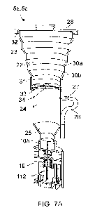
of FIG. 6.
In particular, the delivery consumable 5a, 5c of FIGS. 6A and 6B includes a
collapsible
portion 22, an intermediate portion 24, and a connector 19.
[0090] FIG. 7A shows the delivery consumable 5a, 5c in a full state, prior to
collapsing the
collapsible portion 22. FIG. 7B shows the delivery consumable 5a, 5c after
partially
collapsing the collapsible portion 22. As shown in FIG. 7B, when the
collapsible portion 22
is collapsed the collapsible wall 23 is folded about the inward and outward
folds 30a, 30b,
reducing the distance between the first end 31 and the second end 32 and
therefore
reducing the internal volume in the collapsible portion 22 and within the
delivery
.. consumable 5a, 5c as a whole.
[0091] As shown in FIGS. 7A and 7B, the delivery consumable 5a, 5c may also
include a
divider 33 arranged to separate the internal volumes of the collapsible
portion 22 and the
intermediate portion 24. The divider 33 includes a valve 34, such as two-way
valve. The
valve 34 permits passage of air (or other gas within the delivery consumable
5a, 5c) from
.. the intermediate portion 24 to the collapsible portion 22 when the delivery
consumable 5a,
5c is being filled with fluid, and permits passage of air (or other gas within
the delivery
consumable 5a, 5c) from the collapsible portion 22 to the intermediate portion
24 as the
collapsible portion 22 is collapsed to transfer the fluid to the bioreactor.
The divider 33 may
act to prevent the fluid from moving from the intermediate portion 24 into the
collapsible
portion 22.
[0092] Additionally or alternatively, the divider 33, in particular the valve
34, may restrict
air flow through the valve in order to limit the rate at which the collapsible
portion 22 can be
collapsed, and therefore limit the pressure that can be applied to the fluid
and limit the rate
at which the fluid is transferred to the bioreactor. This may help to protect
the cells or other
delicate constituents of the fluid from damage caused by flowing too quickly
through the
needle connecting the delivery consumable 5a, 5c to the bioreactor.
CA 03172350 2022-08-22
WO 2021/181077 PCT/GB2021/050577
17
[0093] Also shown in FIGS. 7A and 7B the first septum seal 108 of the
connector 19 seals
the end of the intermediate portion 24. As described with reference to FIG. 5,
the
connector 19 is actuatable to move a hollow needle 112 relative to the first
septum seal
108 and to puncture first septum seal 108 to create a fluid connection across
the first
septum seal 108.
[0094] FIGS. 8A and 8B illustrate the delivery consumable 5a, 5c of FIGS. 6,
7A, and 7B
with different volumes of fluid. In the example of FIG. 8A the delivery
consumable 5a, 5c
may hold about 50m1 of fluid, and in the example of FIG.8B the delivery
consumable 5a, Sc
may hold about 100m1 of fluid. In examples, the 50mlor 100m1 fluid is a cell
suspension.
The difference in volume may be accommodated by having different size delivery
consumables 5a, Sc, with different size intermediate portions 24 and
collapsible portions
22. Alternatively, the difference may be accounted for within the volume of
the same
delivery consumable 5a, Sc, by only partially expanding the collapsible
portion 22 when the
amount of fluid is less than a maximum capacity.
[0095] FIGS. 9 to 11 illustrate another example of the delivery consumable 5a,
Sc. In this
example, as shown in FIG. 9, the delivery consumable 5a, Sc comprises a
connector 19, a
collapsible portion 37, and an intermediate portion 38 between the collapsible
portion 37
and the connector 19.
[0096] The connector 19 may be the same connector 19 as described with
reference to
the examples of FIGS. 4A to S. In particular, the connector 19 is connectable
to the
bioreactor (4, see FIG. 3), in particular the connecter interface (21, see
FIG. 3) of the
bioreactor 4. The connector 19 may include a needle that is actuatable to
puncture a seal
of the delivery consumable 5a, Sc and create a fluid connection between the
delivery
consumable 5a, Sc and the bioreactor 4.
[0097] In other examples, the connector of the delivery consumable 5a, Sc may
comprise
an openable valve, a breakable seal, or other sealing mechanism that initially
seals the
delivery consumable 5a, Sc and is openable once the connector is connected to
the
bioreactor to provide a fluid connection between the delivery consumable 5a,
Sc and the
bioreactor.
[0098] In this example, the fluid, for example a cell suspension, is held
within the
intermediate portion 38 and within the collapsible portion 37. During use
compression of
the collapsible portion 37 urges the fluid through the fluid connection
provided by the
connector 19.
[0099] In FIG. 10 the connector 19 is only partially shown. As illustrated in
FIG. 10, the
collapsible portion 37 is formed of a collapsible wall 39 having a series of
alternating
CA 03172350 2022-08-22
WO 2021/181077 PCT/GB2021/050577
18
inward folds 40a and outward folds 40b. The collapsible wall 39 may be called
a bellows
wall.
[00100] In this example, a first end 41 of the collapsible wall 39 is attached
to the
intermediate portion 38, and a second end 42 of the collapsible wall 39 is
disposed
opposite to the first end 41. A cap 43 closes the second end 42. As with the
previous
examples, the cap 43 may include an engaging feature 44 that is engageable by
another
part of the cell processing system (1, see FIG. 1), in particular an actuator
in the cell
processing housing (2, see FIG. 1).
[00101] The first end 41 of the collapsible wall 39 can be attached to the
intermediate
portion 38 by clamping, adhering, or welding. In other examples, the first end
41 of the
collapsible wall 39 and the intermediate portion 38 are integrally moulded,
for example
overmoulded, and formed as one component. The cap 43 can be attached to the
second
end 42 of the collapsible wall 39 by clamping, adhering, or welding.
[00102] In this example, the first end 41 of the collapsible wall 39 is larger
than the second
end 42 of the collapsible wall 39, and so the collapsible portion 37 is
frustoconical. The
frustoconical collapsible portion 37 tapers away from the intermediate portion
38. That is,
the frustoconical collapsible portion 37 has a larger cross-section at the
intermediate
portion 38 than at the second end 42. As shown in FIG. 11, the frustoconical
collapsible
portion 37 with the larger (first) end 41 being attached to the intermediate
portion 38
ensures that fluid cannot be trapped within the folds 40a, 40b of the
collapsible wall 39
when the collapsible wall 39 is collapsed. In particular, the inward and
outward folds 40a,
40b cause the collapsed part the collapsible wall 39 to be angled downwards,
towards the
intermediate portion 38, thereby preventing fluid from becoming trapped
between the folds
40a, 40b. Accordingly, even though the frustoconical collapsible portion 37 is
arranged like
an inverted funnel, advantageously fluid is less liable to be retained in the
folds of the
collapsible wall 39. This is particularly advantageous for a cell delivery
consumable 5a as
the cells are valuable and delicate and it is preferable to transfer as many
cells as possible
into the bioreactor and retain as few as possible in the cell delivery
consumable 5a.
[00103] As shown in FIG. 10, the intermediate portion 38 includes a funnel
portion 45
attached to the first end 41 of the collapsible portion 37. The funnel portion
45 narrows in a
direction away from the collapsible portion 37 and the tubular portion 46
extends to the
connector 19. As with the previous examples, a plug seal 47 may seal the end
of the
intermediate portion 38, in particular the tubular portion 46. The plug seal
47 can be
punctured by the hollow needle (112, see FIG. 5) of the connector 19 as
previously
described.
CA 03172350 2022-08-22
WO 2021/181077 PCT/GB2021/050577
19
[00104] As shown in FIG. 10, the intermediate portion 38 also includes a feed
tube 26 and
spigot 27 attaching the feed tube 26 to the intermediate portion 38. The feed
tube 26 can
be used to fill the delivery consumable 5a, 5c with a fluid, for example a
cell suspension or
cell culturing media, and can then be detached or sealed.
.. [00105] FIGS. 12A and 12B illustrate another example of the delivery
consumable 5a, 5c.
In this example, as shown in FIG. 12A, the delivery consumable 5a, 5c
comprises a
connector 19, a collapsible portion 49, and an intermediate portion 50 between
the
collapsible portion 49 and the connector 19. In FIG. 12B the connector 19 is
only partially
shown.
[00106] The connector 19 may be the same connector 19 as described with
reference to
the examples of FIGS. 4A to 5. In particular, the connector 19 is connectable
to the
bioreactor (4, see FIG. 3), in particular the connecter interface (21, see
FIG. 3) of the
bioreactor 4. The connector 19 may include a needle that is actuatable to
puncture a seal
of the delivery consumable 5a, Sc and create a fluid connection between the
delivery
consumable 5a, Sc and the bioreactor 4.
[00107] In other examples, the connector of the delivery consumable 5a, Sc may
comprise
an openable valve, a breakable seal, or other sealing mechanism that initially
seals the
delivery consumable 5a, Sc and is openable once the connector is connected to
the
bioreactor to provide a fluid connection between the delivery consumable 5a,
Sc and the
bioreactor.
[00108] In this example, the fluid, for example a cell suspension, is held
within the
intermediate portion 50 and within the collapsible portion 49. During use
compression of
the collapsible portion 49 urges the fluid through the fluid connection
provided by the
connector 19.
[00109] In the example of FIGS. 12A and 12B, the collapsible portion 49
comprises a first
collapsible portion 49a and a second collapsible portion 49b. Each of the
first and second
collapsible portions 49a, 49b has a frustoconical form. Each of the first and
second
collapsible portions 49a, 49b has a first end 51a, 51b and a second end 52a,
52b, the first
ends 51a, 51b being larger than the second ends 52a, 52b. The first and second
collapsible portions 49a, 49b are joined end-to-end such that they define a
single internal
volume and collapse in the same direction. In the illustrated example the
second ends 52a,
52b (i.e., the smaller ends) are joined to each other. The first end 51a of
the first
collapsible portion 49a is attached to the intermediate portion 50. The first
end 51b of the
second collapsible portion 49b is provided with a cap 53. Accordingly, from
the
intermediate portion 50 the collapsible portion 49 tapers inwards to a
narrower waist 55
and then tapers outwards to the first end 51b of the second collapsible
portion 49b.
CA 03172350 2022-08-22
WO 2021/181077 PCT/GB2021/050577
[00110] The first end 51a of the first collapsible portion 49a can be attached
to the
intermediate portion 50 by clamping, adhering, or welding. In other examples,
the first end
51a of the first collapsible portion 49a and the intermediate portion 50 are
integrally
moulded, for example overmoulded, and formed as one component. The cap 53 can
be
5 attached to the first end 51b of the second collapsible portion 49b by
clamping, adhering,
or welding.
[00111] As with the previous examples, the cap 53 may include an engaging
feature 54
that is engageable by another part of the cell processing system (1, see FIG.
1), in
particular an actuator in the cell processing housing (2, see FIG. 1).
10 [00112] As illustrated in FIG. 12B, the collapsible portion 49 is formed
of a collapsible wall
56 having a series of alternating inward folds 57a and outward folds 57b. The
collapsible
wall 56 may be called a bellows wall.
[00113] As shown in FIG. 12B, the intermediate portion 50 includes a funnel
portion 58
attached to the first end 51a of the first collapsible portion 49a. The funnel
portion 58
15 narrows in a direction away from the collapsible portion 49 and a
tubular portion 59
extends to the connector 19. As with the previous examples, a plug seal 60,
for example a
septum seal, may seal the end of the intermediate portion 50, in particular
the tubular
portion 59. The plug seal 60 can be punctured by the hollow needle (112, see
FIG. 5) of
the connector 19 as previously described.
20 [00114] As with previous examples, the intermediate portion 50 may also
include a feed
tube and spigot attaching the feed tube to the intermediate portion 50. The
feed tube can
be used to fill the delivery consumable 5a, Sc with a fluid, for example a
cell suspension or
cell culturing media, and can then be detached or sealed.
[00115] In examples, referring to all of the examples described above, the
collapsible wall
23, 39 of the collapsible portion 22, 37 of the delivery consumable 5a, Sc may
be made
from silicone. In other examples the collapsible wall 23, 39 of the
collapsible portion 22, 37
of the delivery consumable 5a, Sc may be made from another polymer, for
example
polyethylene (PE), or a thermoplastic elastomer (TPE) such as polypropylene.
Advantageously, the material of the collapsible wall 23, 29 may have a low
elasticity or
return force so that the collapsible wall 23, 39 retains its collapsed state
after being
collapsed. The collapsible wall 23, 39 may have an external or internal
coating to reduce
permeability, particularly gas permeability.
[00116] The various example delivery consumables 5a, Sc described above have
been
described in relation to delivering a fluid to the bioreactor (4, see FIG. 3),
in particular a cell
suspension and/or a cell culturing media. However, it will be appreciated that
the delivery
CA 03172350 2022-08-22
WO 2021/181077 PCT/GB2021/050577
21
consumables 5a, 5c may additionally or alternatively be used for delivering
other fluid
materials or media to the bioreactor (4, see FIG. 3).
[00117] FIGS. 13A to 13E illustrate use of the delivery consumable 5a, 5c for
delivering a
fluid to a bioreactor (4, see FIG. 3). FIGS. 13A and 13E illustrate the
process using the
delivery consumable 5a, 5c of FIGS. 6 to 7B, but it will be appreciated that
the same
process applies for the delivery consumable 5a, 5c of FIGS. 9 to 11, and the
delivery
consumable of FIGS. 12A and 12B also.
[00118] As shown in FIG. 13A, when the delivery consumable 5a, 5c is full,
with the fluid
received in the intermediate portion 24, the collapsible portion 22 is in an
extended state.
The connector 19 is in a non-activated state, shown in FIG. 5, with a first
end 114 of the
needle 112 spaced from the first septum seal 108 of the connector, and a
second end 116
of the needle 112 spaced from the second septum seal 110 of the connector 19.
In this
configuration the delivery consumable 5a, 5c can be transported and handled,
and can be
connected to the connector interface (21, see FIGS. 3 and 4B).
[00119] As shown in FIG. 13B, actuation of the connector 19 causes the
connector 19 to
collapse as described with reference to FIG. 5, such that the first end 114 of
the hollow
needle 112 pierces the first septum seal 108 and also any additional seal on
the
intermediate portion 24. In addition, the second end 116 of the hollow needle
112 pierces
the second septum seal 110 of the connector 19 and also pierces any additional
seal on
the bioreactor (4, see FIG. 3). Accordingly, the needle 112 creates a fluid
connection
between the delivery consumable 5a, Sc and the bioreactor (4, see FIG. 4B).
[00120] FIGS. 130 and 13D shows compression of the collapsible portion 22,
causing the
volume within the delivery consumable 5a, Sc to be reduced and the fluid to be
urged
through the needle 112 and into the bioreactor (4, see FIG. 3). The
collapsible wall 23 of
the collapsible portion 22 concertinas as a result of the inward and outward
folds 30a, 30b.
[00121] In the example of the delivery consumable 5a, Sc of FIGS. 6 to 7B,
collapsing the
collapsible portion 22 drives air through the valve 34 and urges the fluid
through the hollow
needle 112 and into the bioreactor (4, see FIG. 3). In the example of the
delivery
consumable 5a, Sc of FIGS. 9 to 12B, collapsing the collapsible portion 37
urges the fluid
through the hollow needle 112 and into the bioreactor (4, see FIG. 3).
[00122] Once the desired volume of the fluid, for example all of the fluid,
has been
transferred into the bioreactor (4, see FIG. 3) the connector 19 is disengaged
so that the
hollow needle 112 moves away from the first septum seal 108, as shown in FIG.
13E.
Additionally, the hollow needle 112 may move away from the second septum seal
110. In
this state the internal volume of the delivery consumable 5a, 5b is sealed
from the
CA 03172350 2022-08-22
WO 2021/181077 PCT/GB2021/050577
22
connector 19, and the delivery consumable 5a, 5c and connector 19 can be
disconnected
from the bioreactor (4, see FIG. 3).
[00123] Throughout the description and claims of this specification, the words
"comprise"
and "contain" and variations of them mean "including but not limited to", and
they are not
intended to (and do not) exclude other components, integers or steps.
Throughout the
description and claims of this specification, the singular encompasses the
plural unless the
context otherwise requires. In particular, where the indefinite article is
used, the
specification is to be understood as contemplating plurality as well as
singularity, unless
the context requires otherwise.
[00124] Features, integers, characteristics or groups described in conjunction
with a
particular aspect, embodiment or example of the invention are to be understood
to be
applicable to any other aspect, embodiment or example described herein unless
incompatible therewith. All of the features disclosed in this specification
(including any
accompanying claims, abstract and drawings), and/or all of the steps of any
method or
process so disclosed, may be combined in any combination, except combinations
where at
least some of such features and/or steps are mutually exclusive. The invention
is not
restricted to the details of any foregoing embodiments. The invention extends
to any novel
one, or any novel combination, of the features disclosed in this specification
(including any
accompanying claims, abstract and drawings), or to any novel one, or any novel
combination, of the steps of any method or process so disclosed.