Note: Descriptions are shown in the official language in which they were submitted.
CA 03174104 2022-08-31
WO 2021/195284
PCT/US2021/023988
CONTAINER AND LOAD BASKET FOR THERMAL MANAGEMENT FOR
PROCESSING IN HIGH PRESSURE APPLICATION
CROSS-REFERENCE TO RELATED APPLICATION
This patent application claims priority of U.S. Patent Application Serial No.
63/001,047, filed on March 27, 2020, the entire disclosure of which is hereby
incorporated
by reference herein for all purposes.
BACKGROUND
High pressure processing (also "HPP") is used to reduce the microbial load on
foods, beverages, cosmetics, pharmaceuticals and other products without
significantly
altering the characteristics of the processed product. The pressure level
required for HPP
to be successful is typically at least 4,000 bar.
Traditional equipment for treatment of beverages and other liquids as well as
pumpable foods and other products by HPP is based on the processing of the
products after
having been placed as individual units into flexible packaging, for example,
bottles,
cartons, or pouches. The individual units are grouped or consolidated within a
larger
reusable load basket which is sized and shaped to fit into a wire wound high
pressure vessel
(also referred to as "wire wound vessel" or "high pressure vessel").
Such high pressure vessel is filled with water which serves as the
pressurizing
medium. Once the wire wound vessel has been filled and closed, high capacity
pumps
introduce additional water into the pressure vessel so that the pressure
therein is increased
from about 4,000 to 10,000 bar. This pressure is maintained for a sufficient
length of time,
from a few seconds to several minutes, to reduce the microbial load on the
products being
treated. The particular pressure level and the time duration of such pressure
are specific to
the product being processed.
Once the desired level of inactivation of the microorganisms has been
achieved, the
pressure in the vessel is released and the load basket is removed from therein
so that the
individual packages can be extracted. The processed product has, after being
exposed to
high pressure and hold time, been pasteurized, the microbial load has been
reduced, and an
extended shelf life has been achieved.
HPP has also been used in the "bulk" processing of the product, especially
pumpable products. The pumpable products are placed in a large flexible bag or
bladder
-1-
CA 03174104 2022-08-31
WO 2021/195284
PCT/US2021/023988
type container located inside the pressure vessel thereby to occupy a
significant proportion
of the useful volume within the pressure vessel. The bladder is then
pressurized by the
pressure media in much the same way as if a load basket were used.
During an HPP cycle, the processing media, as well as the product being
processed,
are subject to an adiabatic temperature rise by virtue of the pressure being
applied thereto.
This increase in temperature is typically 3 C per 1,000 bar. Thus, at an
operating pressure
of 6,000 bar, the temperature increase can be approximately 18 C.
Different materials exhibit different adiabatic properties so that with
increase in
pressure, the temperature increase may vary. This can create a layered or
stratified
temperature distribution along the height or depth of the pressure media or
product
processed in an HPP pressure vessel. This thermal distribution in the pressure
vessel can
result in a significant temperature variation range in the product being
processed.
Applicant has identified layering effects that under certain circumstances may
have a
negative effect on the end result of the final product being processed in an
HPP pressure
vessel. The lower portion of the contained pressure media and product may be
significantly
colder than the upper portion of the contained pressure media and product. In
some tests
conducted by applicant, the upper 60% of the pressurized volume was more
temperature
homogenized than the lower 40% of the pressurized volume.
Applicant's tests also have indicated that the stratification or layering of
the
temperature of the processing media or pumpable product during HPP is due to
changes in
the density of the processing medium or pumpable product caused by the
pressure applied
therein. As a result, the colder processing media or pumpable product tends to
sink while
the warmer processing media or pumpable product tends to rise.
The foregoing temperature stratification or layering may not be of significant
concern or an important factor in a normal or standard HPP process. However,
if HPP is
carried out at a specific temperature, especially within a narrow temperature
range, for
example, when processing dairy products to achieve a desired pasteurization
level, then the
temperature stratification of the processing medium as well as the dairy
product can be of
vital significance. The present disclosure seeks to address this
stratification of the
temperature of the processing medium and/or product being processed in an HPP
system.
-2-
CA 03174104 2022-08-31
WO 2021/195284
PCT/US2021/023988
DESCRIPTION OF THE DRAWINGS
The foregoing aspects and many of the attendant advantages of this invention
will
become more readily appreciated as the same become better understood by
reference to the
following detailed description, when taken in conjunction with the
accompanying
drawings, wherein:
FIGURE 1 discloses a load basket for receiving and holding packaged products
for
HPP;
FIGURE 2 is a pictorial view of an embodiment of an HPP load basket in
accordance with the present disclosure;
FIGURE 3 is a cross-sectional view of FIGURE 2, taken along lines 3-3 thereof;
FIGURE 4 is a cross-sectional view similar to FIGURE 3 of a further embodiment
of an HPP load basket in accordance with the present disclosure;
FIGURE 5 is a cross-sectional view of a further embodiment of a further HPP
load
basket in accordance with the present disclosure;
FIGURE 6 is a cross-sectional view similar to FIGURE 5 of a further embodiment
of the present disclosure;
FIGURE 7 is an isometric view of an HPP load basket in accordance with the
present disclosure;
FIGURE 8 is a cross-sectional view of FIGURE 7 taken along lines 8-8 thereof
and
shown within a pressure vessel, also in cross-section;
FIGURE 9 is a longitudinal cross-sectional view of the HPP basket of FIGURE 7
taken along lines 9-9 thereof;
FIGURE 10 is an embodiment of a bulk container in accordance with the present
disclosure;
FIGURE 11 is a cross-sectional view of FIGURE 10 taken along lines 12-12
thereof;
FIGURE 12 is a view similar to FIGURE 10, but in accordance with a further
embodiment to the present disclosure;
FIGURE 13 is a cross-sectional view of FIGURE 12 taken along lines 14-14
thereof;
FIGURE 14 is a pictorial view of a further HPP bulk container in accordance
with
the present disclosure;
FIGURE 15 is an exploded view of FIGURE 14; and
-3-
CA 03174104 2022-08-31
WO 2021/195284
PCT/US2021/023988
FIGURES 16, 17, and 18 are similar to FIGURES 7, 8, and 9, but with the
addition
of bulk container or bladder positioned therein to occupy the interior of the
load basket.
DETAILED DESCRIPTION
In the following description and in the accompanying drawings, corresponding
systems, assemblies, apparatus and units may be identified by the same part
number, but
with an alpha suffix. The descriptions of the parts/components of such systems
assemblies,
apparatus, and units that are the same or similar are not repeated so as to
avoid redundancy
in the present application.
The description set forth below in connection with the appended drawings,
where
like numerals reference like elements, is intended as a description of various
embodiments
of the disclosed subject matter and is not intended to represent the only
embodiments. Each
embodiment described in this disclosure is provided merely as an example or
illustration
and should not be construed as preferred or advantageous over other
embodiments. The
illustrative examples provided herein are not intended to be exhaustive or to
limit the
disclosure to the precise forms disclosed. Similarly, any steps described
herein may be
interchangeable with other steps, or combinations of steps, in order to
achieve the same or
substantially similar result.
In the following description, numerous specific details are set forth in order
to
provide a thorough understanding of exemplary embodiments of the present
disclosure. It
will be apparent to one skilled in the art, however, that many embodiments of
the present
disclosure may be practiced without some or all of the specific details. In
some instances,
well known process steps have not been described in detail in order not to
unnecessarily
obscure various aspects of the present disclosure. Further, it will be
appreciated that
embodiments of the present disclosure may employ any combination of features
described
herein.
The present application may include references to "directions," such as
"forward,"
"rearward," "front," "back," "ahead," "behind," "upward," "downward," "above,"
"below,"
"horizontal," "vertical," "top," "bottom," "right hand," "left hand," "in,"
"out," "extended,"
"advanced," "retracted," "proximal," and "distal." These references and other
similar
references in the present application are only to assist in helping describe
and understand
the present disclosure and are not intended to limit the present invention to
these directions.
-4-
CA 03174104 2022-08-31
WO 2021/195284
PCT/US2021/023988
The present application may include modifiers such as the words "generally,"
"approximately," "about," or "substantially." These terms are meant to serve
as modifiers
to indicate that the "dimension," "shape," "temperature," "time," or other
physical
parameter in question need not be exact, but may vary as long as the function
that is
required to be performed can be carried out. For example, in the phrase
"generally circular
in shape," the shape need not be exactly circular as long as the required
function of the
structure in question can be carried out.
The present application refers to "processing medium" used in the HPP system
for
applying high pressure to the product being processed. Such processing medium
is also
referred to in the application as processing fluid or processing water as well
as referred to
as pressurized/pressure medium, pressurized/pressure fluid or pressurized
water. All of
these terms are to be used interchangeably.
In addition, the present application refers to the pressure vessel of an HPP
apparatus. Such pressure vessel is also referred to as wire wound vessel or
simply vessel.
These terms are to be considered as synonymous.
Also, in the present application the term "container" shall generically refer
to both
open type load baskets and closed containers. In this specification the term
"load basket"
will be used to refer to an open type container and the term "container" will
be used to refer
to a closed container, so as to help avoid confusion between these types of
containers.
Further, the present application refers to a "product" or "products" that are
subjected
to or treated by HPP using the containers of the present disclosure. Such
product(s) may
include all manner of foods, including pumpable foods or beverages, as well as
non-food
products, such as cosmetics, pharmaceuticals, and organic materials and
substances,
wherein the control of pathogens is desirable.
As shown in FIGURE 1, a load basket 20 for high pressure processing includes a
generally cylindrical body 22 having first and second ends 24, 26 and a
curvilinear
sidewall 28 extending therebetween. The cylindrical body 22 may be constructed
of any
material suitable for high pressure processing, whether a metal or a polymer.
While the
body 22 is illustrated with a generally cylindrical shape with a generally
circular cross-
section, the body 22 could have different cross-sectional forms such as
square, rectangular,
triangular, hexagonal or any other suitable polygonal shape. As shown, the
cylindrical
body 22 defines an interior volume 30 for receiving packaged food products or
other
-5-
CA 03174104 2022-08-31
WO 2021/195284
PCT/US2021/023988
products to be processed in a high-pressure processing chamber (not shown).
Volume 30
could also be filled with a thin walled liner bag for bulk processing.
With continued reference to FIGURE 1, the load basket 20 may include first and
second top openings 32, 34 in the sidewall 28 of the cylindrical body 22,
through which
the packaged food products or other products may be inserted into and removed
from the
basket 20. As shown, the first and second top openings 32, 34 are separated by
a middle
bridging portion 36 of the sidewall 28, which may be used to provide a
gripping point for
lifting the load basket 20 or to add rigidity to the cylindrical shape of the
load basket. The
first and second top openings 32, 34 may terminate at or near the first and
second ends 24,
26, respectively.
As shown in FIGURE 1, first and second outer bridging portions 40, 42 of the
sidewall 28 are provided adjacent the first and second top openings 32, 34,
respectively, to
assist in maintaining the generally cylindrical shape of the cylindrical body
22, and/or to
also provide stiffness or rigidity to the cylindrical body 22. As shown, the
widths of the
first and second outer bridging portions 40, 42 may be different from each
other. The
bridging portions 40, 42 also may be used as a gripping point(s) for lifting
or otherwise
manipulating the cylindrical body 22.
A plurality of fluid passage holes 44 may be provided through the sidewall 28
of
the cylindrical body 22 to allow the pressure-transmitting medium of the high
pressure
processing chamber to fill the interior 30 with pressure media before the
pressure increase
initiates. In addition, or alternatively, the fluid passage holes 44 may allow
the pressure-
transmitting fluid to drain out of the interior volume 30 during and/or after
processing.
While the fluid passage holes 44 are shown as being positioned in a bottom
portion of the
cylindrical body 22, it will be appreciated that the fluid passage holes 44
may be positioned
at any suitable location, and in any suitable quantity.
In addition, or alternatively, auxiliary fluid passage holes 46 may be
provided in at
least one of the first or second ends 24, 26 of the cylindrical body 22.
Further as shown in FIGURE 1, a plurality of longitudinal indentations 48 may
extend along an exterior surface of the sidewall 28 between the first and
second ends 24,
26 of the body 22. Such indentations provide the load basket 20 with increased
stiffness
and/or rigidity. Such indentations may also exist as longitudinal protrusions
The features of load basket 20 described above may be employed in the load
baskets
described below and shown in FIGURES 2-9. So as to avoid redundancy, the
description
-6-
CA 03174104 2022-08-31
WO 2021/195284
PCT/US2021/023988
of such features will not be repeated, but with the understanding that such
features may
apply to the embodiments of the load baskets shown in FIGURES 2-9.
The present disclosure below provides various embodiments of both load basket
and bulk containers designed to address the temperature stratification or
layering
phenomena that occurs in a typical HPP application. In this regard, load
baskets and bulk
containers are provided wherein the typical bottom portion of the load basket
or container
is truncated or filled in so as to eliminate a bottom well section of the
basket/container.
The cooler, heavier density processing medium or pumpable product tend to
collect in the
bottom well and thus not mix with the warmer processing medium or pumpable
product
fluid located above. Also, the product being processed is kept away from the
lower portion
of the pressure vessel where the colder processing medium tends to collect.
Also, it is desirable that the load basket and/or bulk container retain its
orientation
in a processing chamber so that the removed or modified lower section of the
load
basket/container remains in correct orientation. Typically, a processing
chamber for
receiving the load basket/bulk container is cylindrical in cross section, and
does not provide
any structure or other means for orienting the load basket or bulk container
in any particular
rotational position relative to its longitudinal axis.
FIGURES 2 and 3 illustrate a load basket 60 that is similar in construction to
the
load basket 20 of FIGURE 1, with the exception that the bottom portion of the
load basket
is truncated. A floor 62 extends across the lower portion of the load basket
so as to
eliminate the majority of the concave interior lower portion of the body
portion 64 of the
load basket as part of the volume for holding product during HPP processing.
As shown
in FIGURE 3, the floor 62 may be constructed from the same material as the
load basket
body portion 64. Also, the floor is shown as substantially flat or horizonal
but need not be
so. Rather, the floor can be ridged or otherwise contoured. Further, arcuate
supports 68 or
other supports are used to support the load basket for HPP processing. The
supports can
be spaced long the length of the body 64. It is to be understood that the
other forms of
supports can be used to form a closed or an open structure beneath the floor
62.
With the elimination of the concave lower portion of the body portion 64,
there is
less likelihood that the colder and denser processing fluid circulating
through the interior
66 of load basket 60 will be trapped at the bottom of the load basket. Rather,
there is more
of a likelihood that the processing fluid will circulate through the body
portion 64, so as to
-7-
CA 03174104 2022-08-31
WO 2021/195284
PCT/US2021/023988
more thoroughly mix than if the load basket body portion were constructed in a
typical
circular cross-sectional shape, such as shown in FIGURE 1.
Although not shown, holes may be formed in the floor 62 to enable processing
medium to pass through the floor thereby to enhance the mixing of the
processing medium
within the interior 66 of load basket 60 and within the surrounding high
pressure chamber
within which the load basket is positioned during HPP.
It can be appreciated that the floor 62 may be located at various distances
from the
bottom of the body portion 64 that would exist if the body portion were not
truncated by
the floor 62. Although the floor 62 is illustrated as at an elevation of about
70% of the
distance between the nominal bottom of a cylindrical body portion and the
diametrical
center of the body portion, it will be appreciated that the floor 62 can be at
other elevations.
As a non-limiting example, the floor may be at an elevation from 20 to 80% of
the distance
above the bottom of the body portion relative to the center of the nominally
cylindrically
shaped body portion.
FIGURE 4 is a cross-sectional view of a load basket 70 which is constructed
similarly to load basket 60 but with a floor 72 composed of a material that
exhibits higher
adiabatic properties than the body portion 74. As a consequence, when pressure
is applied
by the fluid medium in a high-pressure chamber, the floor portion 72 will be
heated to a
higher temperature than the body portion 74 of the load basket 70. In this
regard, the
floor 72 can be composed of a material that increases in temperature more than
both food
and pressure media do. Thus, the processing water that contacts the floor 72
will be heated
to a higher temperature than if the floor were composed of the same material
as the body
portion 74 of the load basket. Such heating of the processing medium adjacent
the floor 72
promotes circulation of such processing medium.
Moreover, although not shown, holes can be formed through the thickness of the
floor 72. Such holes can function as ejectors, i.e., when the warmer fluid
starts to rise
inside the vessel the ejectors will pull colder water through the holes, from
underneath the
floor, and into the interior 76 to get mixed with the warmer water therein.
Also, a support structure 78, which can be similar to support structure 68,
can be
used to support the load basket for HPP processing.
Various types of materials exhibiting relatively high adiabatic activity can
be
employed to form the floor 72. For example, such materials might be composed
of low-
-8-
CA 03174104 2022-08-31
WO 2021/195284
PCT/US2021/023988
density polyethylene (LDPE), high density polyethylene (HDPE), or ultra high
molecular
weight polyethylene (UHMWPE).
FIGURE 5 illustrates an embodiment of the present disclosure wherein load
basket 80 includes a substantially circular cross-sectional shaped body 82 as
in FIGURE 1;
however, a floor or partition 84 extends across the bottom portion of the
interior 86 of the
body portion 82 of the load basket so as to effectively truncate the interior
volume of the
load basket 80 to essentially correspond to the interior volumes 66 and 76
shown in
FIGURES 3 and 4. In that the floor or partition 84 serves to truncate the
interior volume
86 as in the embodiments discussed above, as such the load basket 80 is
considered to have
an truncated lower section.
The load basket 80 has the advantage of the rigidity of a load basket in the
form of
a complete circle or cylinder cross section at least in the middle and ends of
the body
portion 82, but at the same time preventing the denser, cooler processing
medium to collect
and remain stationary at the bottom of the load basket interior 86.
The floor 84 may be constructed of the same material as the body portion 82.
Also,
holes 88 are provided in the load basket below the level of the floor 82, and
holes 89 may
also be provided in the floor 84 to perform the same function as the holes in
floor 72
described above.
FIGURE 6 illustrates a load basket 90 constructed similarly to load basket 80,
but
with the floor 92 composed of a material with higher adiabatic properties than
the body
portion 94 remainder of the load basket. As discussed above, with respect to
load
basket 70, through this construction the floor 92 may be heated to a higher
level during
pressurization of the load basket 90. As a result, processing medium in
contact with the
floor 92, though initially perhaps cooler than the processing medium at the
upper portion
of the load basket, may be sufficiently heated so as to enhance its movement
within the
interior 96 of the load basket. In that the floor or partition 92 serves to
truncate the interior
volume 96 as in the embodiments discussed above, as such the load basket 90 is
considered
to have a truncated lower section.
As with the floor 72, the floor 92 can include through holes 99 formed therein
to
cause the processing medium heated by the floor to pass upwardly into the
interior 96 of
the body 94, thereby further facilitating the movement of the processing
medium within
the interior. Further, as discussed above with respect to load basket 80,
openings 98 can
be formed in the body portion 94 of the load basket below the floor 92 so that
pressurized
-9-
CA 03174104 2022-08-31
WO 2021/195284
PCT/US2021/023988
medium 98 is directed to the floor 92 and then upwardly into the interior 96.
Further, as
with the floor 72, the floor 94 can be composed of various materials, for
example, LDPE,
HDPE, and UHMWPE.
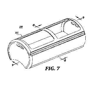
FIGURES 7, 8, and 9 illustrate a further embodiment of the present disclosure
wherein the load basket 100 has an upper body portion 102 similar to that
shown in
FIGURES 2 and 3, but in the place of a transverse floor or partition, the load
basket
includes a lower carrier portion 104 that serves several functions including
as forming the
floor surface 106 of the load basket at an elevation that may correspond to
the elevation of
floors 62, 72, 82, or 92 discussed above as well as supporting the body
portion 102. The
lower carrier portion 104 serves to truncate the load basket 100 as in the
embodiments
discussed above. As such the load basket 100 is considered to have a truncated
lower
section.
Although the carrier portion 102 can be constructed in numerous different
configurations and profiles, the configuration shown in FIGURES 7-9 includes a
flat upper
floor surface 106 and in this case a concave lower bottom surface 108.
Moreover, the
carrier portion 104 can be composed of substantially thicker cross section
than the body
portion 102.
As a consequence, by forming the carrier portion 104 from a higher level
adiabatic
material than the body portion 102, a significant heat source can be provided
for heating
the processing medium that comes into contact with the surfaces of the carrier
portion 104
while also heating the processing medium that flows through the through
openings 110
formed in the carrier portion. As explained above, such through openings 110
can function
as ejectors wherein the processing medium heated by the carrier portion 104 is
ejected into
the interior 112 of the load basket.
As most clearly shown in FIGURE 8, the carrier portion 104 includes
orientation
projections 114 extending laterally from each side of the carrier portion and
also extending
lengthwise of the carrier portion. Such projections serve as low friction
slide bearings as
the load basket 100 is slid into and out of the high-pressure chamber 116 of a
wire wound
vessel. The projections 114 also serve as restrictors that restrict the
downward movement
of processing medium in the clearance gap 117 between the exterior of the load
basket body
102 and the interior surface of the high-pressure chamber 116. Otherwise, the
cooler,
denser processing medium would attempt to flow downwardly through the gap 117
to
collect in the bottom portion of the high-pressure chamber.
-10-
CA 03174104 2022-08-31
WO 2021/195284
PCT/US2021/023988
As also shown in FIGURE 8, projections 118 may in addition extend outwardly
from upper portions of the load basket body 102 to help prevent rotation of
the load
basket 100 once the pressure vessel 116 has been filled with pressure media,
e.g., water
causing the load basket to rise upwardly within the vessel so that the
projections 118 bear
.. against the upper portions of the vessel inside wall. It is to be
understood that other means
may be employed to prevent rotation of the load basket 100. For example, a rod
or other
weighted item or structure could be positioned along the length of the carrier
portion 104
to serve as a ballast to stabilize the load in the basket when the vessel is
filled with pressure
media. In this regard, as an alternative, the carrier portion can be greater
thickness than the
.. load basket body, and thus serve as a ballast to stably retain the load
basket 100 in correct
orientation, as shown in FIGURE 8. Of course, other types of ballast can be
used.
Although the load basket 100 shown in FIGURES 7-9 is constructed with a
carrier
portion 114 of a material having higher adiabatic activity than the body
portion 102, it is to
be understood that carrier portions can be constructed in other configurations
wherein the
.. carrier portion is composed of the same material as the body portion 102.
In this regard,
the wall section of the carrier portion can be substantially thinner than
shown in FIGURES
7 and 8. As such, appropriate bracing or reinforcing can be provided so that
the thinner
constructed carrier portion has sufficient structural integrity to support the
filled load basket
whether within the high pressure chamber 116 or exterior to the chamber, for
example,
when being loaded or unloaded.
Next, FIGURES 10 and 11 discloses a bulk container 120 for use in an HPP
system.
The bulk container 120 includes a flexible body portion 121 having a truncated
bottom
portion or floor 134 as described below. The body portion 121 will first be
discussed. In
this regard, the body portion includes closed off ends 122, which are depicted
as being
recessed. Alternatively, one end of the body portion may be concaved inwardly
and the
other end convexed outwardly. Either configuration enables the containers 120
to be
positioned end-to-end in an efficient manner, for example, when placed into an
HPP vessel.
An inlet closure, for example in the form a valve 123, is located in one or
both of the ends
122 of the container 120. Also, one or more outlet closures, for example in
the form of
.. valves 124, are located on the body portion 121 of the container for
emptying the container,
for example, after HPP. Also, a support structure 128, which can be similar to
support
structures 68 and 78, can be used to support the container 120 for HPP
processing.
-11-
CA 03174104 2022-08-31
WO 2021/195284
PCT/US2021/023988
The body portion 121 is shown as being in the shape of a portion of a
cylinder.
However, the body 121 can be of other cross-sectional shapes, including as a
portion of a
pentagon, hexagon, octagon, etc. Also, the body 121 can be of a desired
diameter or cross-
sectional dimension, as well as of a desired length, so as to provide a
desired volume for
the bulk container as well as a desired aspect ratio (length v. diameter).
Thus, the containers
120 can be of the same diameter, but of different lengths so as to be of
various volumes
and capacities. In this manner, different beverages or other pumpable products
can be
processed at the same time, when the different products may be of different
quantities.
As noted above, the bulk container 120 can be of various sizes and volumes.
For
example, the bulk containers can have a capacity as small as of about 20 to 25
liters, to a
capacity of at least 200 to 250 liters. In this regard, the smallest capacity
bulk containers
may have a diameter of about 250 to 300 mm, while the larger containers may
have a
diameter at least 450 to 475 mm. Of course, the bulk container 120 can be of
an even
smaller capacity and smaller diameter as well as be of an even larger capacity
and a larger
diameter.
Referring to FIGURE 10, the ends 122 of the bulk container 120 have a rounded
corner 125 that transitions into a concave recess 126. Such rounded corners
enable the
containers to be placed end to end without damage to the containers, even if
the containers
are pushed against each other.
It is to be understood that the container end portions 122 can be of a
construction
and shape other than as shown in FIGURE 10. For example, the end portions 122
may be
substantially planar but with a central recess for receiving the inlet valve
123.
The bulk container 120 can be constructed of various materials, which enable
the
container to maintain its shape while also being sufficiently flexible to
adjust to the reduced
volume of the product within the container during HPP. Such reduction in
volume may be
in a range of 0% to up to at least 30%, thereby requiring the volume of the
container to be
reduced by this same percentage. The material from which the bulk container
may be
constructed can include, for example, metallic material or polymer material.
Such material,
as can be appreciated, must be of sufficient flexural strength and sufficient
flexural
modulus to enable the container to substantially reduce in volume while being
rugged
enough for reuse over a desired number of HPP cycles. Such HPP cycles may be
an
indefinite number of cycles. As such the container can be used indefinitely as
long as the
container cleaned to meet food cleanliness and other standards.
-12-
CA 03174104 2022-08-31
WO 2021/195284
PCT/US2021/023988
The typical temperature operating range of an HPP operating cycle is from 0 C
to
50 C. However, the operating temperature may be higher when HPP is used in
conjunction
with heat pasteurization wherein the operating temperature may raise to 65 C
or perhaps
70 C. The material from which the bulk container 120 is constructed is
selected to operate
within this temperature range, or perhaps at lower or even higher
temperatures.
As mentioned above, the bulk container 120 may be composed of a polymer. As a
specific non-limiting example, the polymer may be composed of a thermal
plastic, such as
polyethylene or nylon. As a further non-limiting example, the polymer may be
composed
of low-density polyethylene (LDPE), high density polyethylene (HDPE), or ultra-
high
molecular weight polyethylene (UHMWPE).
As a further non-limiting example, the polymer may have a thickness in the
range
of from about 4 mm to about 12 mm. The thickness may depend upon several
factors, for
example, the type of polymer used, the density of the polymer, the diameter of
the
container, the length of the container, the type of product to be processed,
and the pressure
level to which the product and container is to be subjected.
The bulk container 120 may be used to process products at high pressures and
temperatures than has been the typical operating range for HPP systems. For
example, the
bulk container may be used operating temperatures of at least 130 C or higher
in situations
for both elevated temperatures and pressures are used for sterilization. Such
operating
pressures may be as high as 8,000 bar or even higher. Many thermal plastics
are not
designed to operate in these elevated temperatures and pressures. However,
"high
performance" thermoplastics do exist that are capable to successfully
operating at such
temperatures and pressures, for example polyetheretherketones,
polyamideimides, and
polyimides. Also, the thermoplastic may be reinforced with fiberglass or
carbon fibers to
enhance mechanical and/or thermal properties.
Regardless of the material used to construct the bulk container 120, such
material
must be compliant with applicable safety standards for food or other products
being
processed at the operating temperatures being used.
As noted above, the inlet closure, for example valve 123, may be positioned in
one
or both ends 122 of the bulk container 120 in such a manner that the closure,
at least when
in closed position, is within the outer envelope of the container. This
enables the closure
to be easily opened and closed, while still protecting the valve from damage,
for example,
from adjacent containers during HPP.
-13-
CA 03174104 2022-08-31
WO 2021/195284
PCT/US2021/023988
The outlet closure may be of the same or similar construction to the inlet
closure.
Such outlet closure is located on the container body 121. The container body
121 at the
location of the outlet closure is recessed so that when the outlet closure is
in closed position
or configuration, the closure remains within the outer perimeter or profile of
the container
or within the overall length and width of the container body. As such, the
outlet closure is
protected from being damaged, or causing damage, by undesirable contact with
the HPP
vessel or other containers or surfaces during filling, during the HPP process,
during
removal from the HPP vessel, and during other handling of the container, while
still being
conveniently opened and closed as necessary.
The features of bulk container 120 described above may be employed in the bulk
containers described below and shown in FIGURES 12-15. To avoid redundancy,
such
features will not be repeated, but with the understanding that such features
may apply to
the embodiments of the bulk containers shown in FIGURES 12-15.
As shown in FIGURES 10 and 11, the bulk container 120 has a body portion 121
generally in the shape of portion of a cylinder, but with its bottom truncated
by a floor 134
similar to the manner in which the floor of carrier or load basket 60 is
constructed.
However, the floor 134 has no through openings or holes therethrough since
interior 136
of the bulk container 120 is sealed from the exterior. Nonetheless, the floor
134 functions
in the manner of floor 62 as described above. In this respect, the floor 1344s
may be
constructed from the same material as the body portion121. As such, colder,
more dense
product to be treated within the bulk container 120 does not tend to collect
at the bottom of
the interior 136 of the body 121. Rather, the pumpable product within the body
121 tends
to circulate and move within the interior 136. This promotes better mixing of
the product
within the interior 136 due to the presence of the floor 134 above the bottom
of the nominal
body 121 (i.e., if the body were shaped in a circular cross-sectional
profile).
FIGURES 12 and 13 disclose a bulk container 140 that is similar in shape and
construction to bulk container 130 except that the floor 144 is composed of an
adiabatic
material of higher activity than the material from which the body portion 142
of the
container is formed. As discussed above, including with respect to load basket
70,
constructing the floor 144 in this manner results in the floor being heated to
a higher
temperature than the body 142 during HPP and perhaps also the temperature of
the
pumpable product within the interior 146 of the container 140. As such, the
pumpable
product being treated that comes into contact with the floor 144 will be
heated thereby,
-14-
CA 03174104 2022-08-31
WO 2021/195284
PCT/US2021/023988
which in turn facilitates movement and circulation of the pumpable product
within the
interior 146 of the container. Accordingly, the likelihood of a significant
temperature
gradient within the interior 146 of the bulk container is countered by not
only the presence
of a floor 144 that truncates the bottom of the container, but also the higher
activity
adiabatic material from which the floor is constructed.
Also, a support structure 148, which can be similar to support structures 68,
78
and/or 128, can be used to support the container 140 for HPP processing.
FIGURES 14 and 15 disclose a bulk container 150 that overall has a cylindrical
exterior shape, but with an interior volume 152 similar to the interior
volumes 136 and 146
of the bulk containers of FIGURES 10-13. In this regard, the bulk container
150 includes
a lower carrier portion 154 disposed beneath an upper body portion 156.
As shown in FIGURES 14 and 15, the upper body portion 156 is similar in shape
to the body portions 132 and 142 of the bulk carriers shown in FIGURES 10 and
12.
However, rather than employing a floor similar to floors 134 and 144, the
bottom of the
interior volume 152 is closed off by the top surface 158 of carrier portion
154. Thus, the
cross-sectional shape of the interior volume 152 within the body portion 156
is similar to
that shown in FIGURES 11 and 13. Since the lower carrier portion 154 serves to
truncate
the interior of bulk container 150 in the manner of the embodiments discussed
above, the
bulk container 150 is considered to have a truncated lower section.
The carrier portion 154 is of substantially solid construction to form the
bottom
portion of the bulk container 150 so that the container is of cylindrical
construction overall
as well as to support the bulk container. Thus, the carrier portion 154 has an
outer curved
cross-sectional shape corresponding to the circumference of the body portion
156 of the
bulk carrier 150. The carrier portion 154 may be attached to the body portion
156 by any
convenient means.
Further, the carrier portion 154 may be constructed from a material that may
be
similar to the construction of the carrier portion 104 shown in FIGURES 8 and
9. As such,
the carrier portion 154 will be heated to a higher temperature than the body
portion 156 and
the contents of the bulk carrier 150 as well as the processing medium used to
pressurize the
bulk container. As such, and as explained above with respect to carrier
portion 104, the
higher temperature to which the carrier portion 154 is heated will cause the
pumpable
product within the interior volume 152 that comes in contact with the top
surface 158 to be
-15-
CA 03174104 2022-08-31
WO 2021/195284
PCT/US2021/023988
heated and thereby not remain in the lower portion of the interior volume, but
rather to
circulate within the interior volume.
A series of blind holes 160 are disposed centrally along the length of the
carrier
portion. These holes are used to position the body portion 156 relative the
carrier portion
154 that includes downwardly extending projections, not shown, to closely
engage into the
blind holes. Of course, other means can be used to position the body portion
156 relative
to the carrier portion 154.
Although not shown, the carrier portion 154 may include projections similar to
projections 114 of carrier portion 104 to help restrain the bulk carrier 150
so that the carrier
portion remains beneath the body portion 156.
In addition, although rather than being of substantially solid construction,
the carrier
portion 154 may include cavities or grooves or other features so as to
increase the heat
transfer area of the carrier portion in a manner analogous to fins in a heat
exchanger. As
such, the carrier portion would be more efficient in transferring heat from
the carrier portion
to the work product within the interior volume 152 of the bulk carrier 150.
Figures 16, 17, and 18 illustrate an embodiment of the present disclosure
wherein a
load basket, such as shown in Figures 7, 8, and 9, is employed to hold a
large, bulk
thin-walled bag or bladder 170 that occupies substantially the entire volume
of the interior
112 of the load basket 100. As shown in Figures 16, 17, and 18, the flexible
bag 170
compresses or decreases in volume to correspond to the decrease in volume of
the bag
contents during HPP processing. However, once the pressure of the HPP
processing is
removed, the bag 170 can resume to its nominal volume of the uncompressed
product
within the bag.
The bag 170 can be constructed from appropriate commercially available
materials,
for example rubber or a polymer. Also, appropriate valving maybe utilized in
conjunction
with the bag 170 for filling and emptying the bag. In addition, the bag may be
designed
for a single or limited number of uses, or may be constructed for indefinite
use. If the bag
is designed for more than singular use, it will be necessary to be able to
clean and sterilize
to bag as required by applicable food handling regulations. Of course, the
load basket will
also need to be cleaned and sterilized.
The load basket 100 shown in FIGURES 7, 8, 9, 16, 17 and 18 may include a
carrier
in the manner of, for example, carrier 154 shown in FIGURES 14 and 15, which
may be in
lieu of, or in addition to carrier 104 to thereby help support the upper body
portion 102.
-16-
CA 03174104 2022-08-31
WO 2021/195284
PCT/US2021/023988
It will be appreciated that the examples of the load baskets and closed
containers
disclosed above enable pumpable products to be treated by HPP processing
whether the
products are prepackaged, for instance in bottles or pouches, or in bulk form
in a large thin-
walled bulk bag or bladder or in a bulk container that retains its shape but
is flexible enough
to compress with the compression of the product being treated when subjected
to high HPP
pressure. Further, in such HPP processing the containers are constructed to
counteract the
vertical thermal stratification or layering that commonly occurs in both the
processing
medium and the product being processed during HPP processing due to the
adiabatic
temperature rise in the processing medium and the processed product cause by
the high
pressures imposed during HPP processing. In this regard the containers of the
present
disclosure may: (1) restrict or remove usage of the lower portion of the
pressure vessel,
(2) increase the mixing of the pressure media by use of the injector holes
formed in, for
example, a floor or partition extending across the container so as to avoid a
well in the
lower portion of the container in which colder processing medium or pumpable
product
may collect; and/or (3) are constructed so that the lower portion of the
container is
composed of material exhibiting higher the adiabatic activity or properties
than the upper
or main body portion of the container.
It also will be appreciated that the various containers described above can be
of
different lengths, diameters, weights, volumes, wall thicknesses, materials
and other
parameters depending on, for example, the application being used for HPP
processing as
well as available pressure vessel size or capacity. Further, the size or
capacity of the
container will dictate whether or not the container can be manually handled or
if auxiliary
handling equipment is needed.
It also can be appreciated that by the above construction of the containers
120, 140,
and 150 the contents of the containers can be conveniently and safely stored
in appropriate
facilities both before and after HPP processing, especially at low
temperatures, perhaps
close to or at 0 C, so as not to permit microbial growth. This is enhanced by
the shape and
construction of the containers for ease of handling, as well as by their
material composition.
Further, it can be appreciated that the containers, bags, bladders, etc., that
hold food
or other product to be processed are composed of materials that are suitable
therefor, and
meet all applicable regulations and standards. Further all load baskets,
containers, bags,
bladders, etc. and cleanable before and/after use as also required by
applicable regulations
and standards.
-17-
CA 03174104 2022-08-31
WO 2021/195284
PCT/US2021/023988
While illustrative embodiments have been illustrated and described, it will be
appreciated that various changes can be made therein without departing from
the spirit and
scope of the invention. For example, in addition to protrusions 114 and
supports 68, 78,
128 and 148 discussed above, shims, flanges, rails, bars, runners, slides,
circumferentially
extending hoop or ring sections or members, and other or similar structures
can be used to
extend or protrude beneath the container, whether a load basket or a closed
container, for
supporting the container during the HPP process.
-18-