Note: Descriptions are shown in the official language in which they were submitted.
WO 2021/199010
PCT/1B2021/052809
RECHARGEABLE ELECTRICAL STORAGE DEVICES
FIELD OF THE INVENTION
This invention relates to rechargeable electrical cells and batteries,
including, but not
limited to lithium ion, Nickel metal hydride and lead acid batteries.
BACKGROUND TO THE INVENTION
A secondary cell is an electrochemical cell that can be run as both a galvanic
cell and as
an electrolytic cell, so that it can be discharged by delivering DC power
generated from a
chemical reaction and can be charged by supplying DC current, which reverses
the
chemical reaction. Batteries are collections of cells connected together in
series or
parallel and are classified by the chemistry on which they rely ¨ the most
common being
lithium-, lead-, and nickel-based systems, and Li-ion being the battery of
choice for
portable devices and the electric vehicles. Unless the contrary appears clear
from the
context, the term "battery" is used herein to refer both to batteries and to
cells.
Lead acid batteries comprise a combination of lead plates that are pasted with
electrochemically active materials such as lead dioxide and sponge lead and
are
immersed in a sulfuric acid electrolyte. If these batteries are overcharged,
they produce
hydrogen and oxygen ¨ which can form an explosive mixture. In addition, the
oxygen can
rapidly destroy the positive pasted electrodes.
Other batteries include Nickel-Cadmium (NiCad) batteries and the more recently
developed lithium ion batteries which are currently the most popular batteries
for small
electronic devices such as laptop computers mobile phones and cordless tools,
and has
become increasingly common in these applications. Despite being superior to
NiCad
batteries in many respects, lithium ion batteries hold disadvantages
including:
malfunctioning on charge acceptance, dendritic growth, and elevated
temperature
caused by rapid over-charge ¨ which can lead to thermal runaway.
1
CA 03174506 2022- 10-3
WO 2021/199010
PCT/1B2021/052809
Lithium batteries have earned a reputation for catching fire. The commonly
used lithium
ion battery formulation had been Lithium-Cobalt-Oxide (LiCo02), which was
prone to
thermal runaway in the event of overcharging ¨ which lead to the battery
catching alight
¨ and lithium burns rapidly and at high temperature. However, 1996 a new
formula for
lithium ion batteries was developed with a formulation comprising Lithium-Iron-
Phosphate, known as LiFePO4 or LFP. LFP batteries have a slightly lower energy
density
than Lithium-Cobalt-Oxide batteries, but are intrinsically non-combustible,
and thus vastly
safer.
One of the challenges that hinder the implementation of cells and batteries,
is the need
to charge them over extended periods and during these periods, the cells or
batteries are
unavailable as a source of power.
Attempts have been made to reduce the time required to charge cells or
batteries. One
approach that has been attempted is an increase in charge current, but this
leads to
thermal runaway and gas formation ¨ which leads to destruction of the cell or
battery. In
order to ensure safe operation of a cell or battery and to prolong its useful
life, it is
essential to prevent excessive heat during charging and to ensure that the
temperature
remains below the gas formation threshold.
Another approach that has been followed in an attempt to reducing charge times
for cells
or batteries, is the use of thicker layers of electrochemically active pastes
on electrodes
or thicker electrodes that result in thicker layers of electrochemically
active paste, but this
has led to sulphasion and dendritic growth in the paste and the dendrites can
damage
the separators between electrodes ¨ and thus damage or destroy the cell or
battery.
The present invention provides a storage cell or battery and components
thereof, which
efficiently regulate the charging current through the electrodes and current
collectors, and
which further allow rapid recharge of the cell or battery.
2
CA 03174506 2022- 10-3
WO 2021/199010
PCT/1B2021/052809
SUMMARY OF THE INVENTION
According to a first aspect of the present invention there is provided an
electrical storage
device comprising:
a first electrode comprising a metal electrode that is pasted with a paste of
electrochemically active material which is electrochemically negative;
a second electrode comprising a metal electrode that is pasted with a paste of
electrochemically active material which is electrochemically positive; and
a porous separator disposed between the first electrode and the second
electrode;
wherein the electrical storage device further comprises:
a first current collector in the form of a porous conductive layer disposed
between the
first electrode and the porous separator, the first current collector being in
contact
with the electrochemically negative paste of the first electrode; and
a second current collector in the form of a porous conductive layer disposed
between
the second electrode and the porous separator, the second current collector
being
in contact with the electrochemically positive paste on the second electrode;
The term "porous" includes structures with apertures of any size.
Each of the first current collector and the second current collector may
comprise of a
perforated metal sheet and the term "perforated metal sheet" includes any
sheet-like
structure with perforations there through ¨ and includes metal grids.
The first current collector and the second current collector may be attached
to opposing
sides of the porous separator.
The first current collector and the second current collector may be of
dissimilar materials.
Each of the first electrode, second electrode, first current collector, and
second current
collector, may have a tab to which electrical connections can be made.
3
CA 03174506 2022- 10-3
WO 2021/199010
PCT/1B2021/052809
In an alternative configuration, the first current collector may be attached
to a side of the
first electrode that faces the porous separator and the second current
collector may be
attached to a side of the second electrode that faces the porous separator.
The electrical storage device may form a laminate that has been rolled into a
cylindrical
shape with a separator extending on the outsides of the laminate.
According to another aspect of the present invention there is provided an
installation
comprising the electrical storage device as described herein above, wherein
the first
electrode and the second electrode are connected to a first DC power source
and the first
current collector and the second current collector are connected to a second
DC power
source.
According to a further aspect of the present invention there is provided an
installation
comprising the electrical storage device as described herein above, wherein
the first
electrode and the second electrode are connected to a DC power source and the
first
current collector and the second current collector are connected to a power
consuming
electrical circuit. Alternatively, the first electrode and the second
electrode may be
connected to a power consuming electrical circuit and the first current
collector and the
second current collector may be connected to a DC power source.
The first electrode and the second electrode, and the first current collector
and the second
current collector, may be connected to a power consuming electrical circuit.
The invention extends to a cell comprising a plurality of the electrical
storage devices
described herein above, connected in parallel, wherein the first electrodes of
each of the
electrical storage devices are connected together, the second electrodes of
each of the
electrical storage devices are connected together, the first current
collectors of each of
the electrical storage devices are connected together, and the second current
collectors
of each of the electrical storage devices are connected together.
4
CA 03174506 2022- 10-3
WO 2021/199010
PCT/1B2021/052809
The invention also extends to a battery comprising a plurality of the
electrical storage
devices described herein above, connected in series, wherein the second
electrode of a
first of the electrical storage devices is connected to the first electrode of
a second of the
electrical storage devices, and the first current collector of the first of
the electrical storage
devices is connected to the second current collector of the second of the
electrical storage
devices.
BRIEF DESCRIPTION OF THE DRAWINGS
For a better understanding of the present invention, and to show how the same
may be
carried into effect, reference will now be made by way of non-limiting example
to the
accompanying drawings in which:
Figure 1 shows an exploded three-dimensional pictorial view of a first
embodiment of an
electrical storage cell according to the present invention;
Figure 2 shows a three-dimensional assembled view of the cell of Figure 1;
Figure 3 shows a three-dimensional view of a separator of the cell of Figure
1, with
electrical collectors on each of its sides;
Figure 4 shows a second embodiment of a cell according to the present
invention,
comprising multiple electrodes and separators;
Figure 5 shows a battery according to the present invention, comprising three
of the cells
of Figure 4; and
Figure 6 shows a three-dimensional view of a third embodiment of a cell
according to the
present invention.
DETAILED DESCRIPTION OF THE DRAWINGS
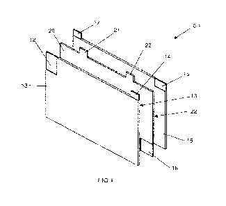
Referring firstly to Figures 1 to 3, a first embodiment of a cell according to
the present
invention is identified generally by reference sign 10.1. The cell 10.1
includes a first
electrode 12, a second electrode 15 and a porous separator 18 of an
electrically isolating
material, extending between the first and second electrodes.
5
CA 03174506 2022- 10-3
WO 2021/199010
PCT/1B2021/052809
In the embodiment of the invention illustrated in Figures 1 and 2, the first
and second
electrodes 12,15 are conventional lead acid battery plates, each comprising a
metal
substrate, typically of a lead alloy, and each of the substrates supporting an
electrochemically active material that is applied in a paste form and is
commonly referred
to as "paste" even if it loses its paste-like consistency after application.
For the sake of
brevity, the term "paste" is used in the detail description of the drawings,
to refer to such
a electrochemically active materials, the term "positive paste" is used for
electrochemically active materials that are electrochemically positive and are
suitable for
use on positive electrodes, and the term "negative paste" is used for
electrochemically
active materials that are electrochemically negative and are suitable for use
on negative
electrodes. By way of non-limiting example, in the case of a lead acid cell
10.1, a suitable
positive paste could comprise lead dioxide and a suitable negative paste could
comprise
sponge lead.
The first electrode 12 serves as a negative electrode and is pasted on both of
its opposing
sides with negative paste 13. The first or negative electrode 12 has a
protruding first tab
14 that extends from its lead alloy substrate and that is thus in conductive
contact with
the negative paste 13 and serves as a negative tab that can be connected to an
external
electrical circuit. Likewise, the second electrode 15 serves as a positive
electrode and is
pasted on both of is opposing sides with positive paste 16. The second or
positive
electrode 15 has a protruding second tab 17 that extends from its lead alloy
substrate
and that is thus in conductive contact with the positive paste 16 and serves
as a positive
tab that can be connected to an external electrical circuit.
The positive and negative electrodes 12,15 and separator 18 are immersed in a
suitable
electrolyte (such as sulfuric acid) that is contained inside a casing (not
shown). The
features of the cell 10.1 described thus far are similar to lead-acid
batteries of the prior
art. In other embodiments of the present invention, the cell 10.1 could be of
materials
suitable for a different type of chemical reaction, e.g. the first negative
and positive
6
CA 03174506 2022- 10-3
WO 2021/199010
PCT/1B2021/052809
electrodes 12,15 could be conventional lithium ion cell electrodes with their
respective
electrochemically negative paste 13 and electrochemically positive paste 16.
Similarly,
the cell 10.1 could be of another electrochemical type, such as Nickel metal
hydride.
The separator 18 has a first current collector 20 on a side of the separator
which faces
the first or negative electrode 12. The first current collector 20 is
preferably of a metal,
which in the illustrated example it is aluminium foil, and the first current
collector has a
protruding tab 21 that can be connected to an external electrical circuit. On
the opposing
side of the separator 18, a second current collector 22 is provided and it
faces the second
or positive electrode 15. The second current collector 22 is also preferably
of metal, which
in the illustrated example is copper foil, and the second current collector
has a protruding
tab 23 that can be connected to an external electrical circuit. In other
embodiments of
the invention, the first and second current collectors may be of the same or
different
conductive materials.
For illustrative purposes, in Figure 1, the top left corner of the negative
paste 13 is not
shown, to reveal the top left corner of the negative electrode 12. Similarly,
the bottom
right corner of the first current collector 20 is not shown, to reveal the
bottom right corner
of the separator 18 and the top right corner of the positive paste 16 is not
show, to reveal
the top right corner of the positive electrode 15. However, for the sake of
simplicity, the
separator 18 is shown as a solid plate (whereas it has multiple apertures
extending
through it) and similarly, the first current collector 20 is shown as a
continuous plate in
Figures 1 and 2, whereas its structure is more complex ¨ as described below
with
reference to Figure 3.
In other embodiments of the invention, conductive surfaces of the first and
second current
collectors 20,22 can be pasted with electrochemically active materials.
Referring to Figure 3, the separator 18 is shown, with the first current
collector 20 and its
tab 21. The second current collector 22 is identical to the first current
collector 21, but is
7
CA 03174506 2022- 10-3
WO 2021/199010
PCT/1B2021/052809
on the opposing side of the separator 18 and in Figure 3, only the tab 23 of
the second
current collector is visible. The separator 18 has a plurality of apertures
24, which are in
horizontal rows in the illustrated embodiment. The first current collector 20
extends from
its tab 21 and extends continuously to form a lateral border 26 along one edge
of the
separator 18, with horizontal ribs 28 extending from the border across the
surface of the
separator 18. The horizontal ribs 28 are spaced apart and define apertures
that are in
register with the apertures 24 of the separator18. The structures of the
separator 18 and
first current collector 20 can be varied in other embodiments of the
invention, but the
current collector should have a substantial outwardly facing surface (formed
in the
illustrated example by the surfaces of the border 26 and ribs 28) and should
not obstruct
the apertures 24 of the separator.
When the electrodes 12,15 and separator 18 are assembled the separator is
compressed
so that the faces of the current collectors 20,22 are in close abutting
contact with the
pastes 13,16 of the adjacent electrodes, to provide the assembled electrical
storage cell
as shown in Figure 2.
In the embodiment of the invention illustrated in Figures 1-3, the current
collectors 20,22
are supported by the separator 18, but in other embodiments, the current
collectors could
each be unsupported or could be supported on its adjacent electrode 12,15,
with the first
current collector 20 on the outside surface of the negative paste 13 and the
second
current collector 22 on the outside surface of the positive paste 16,
respectively.
However, the illustrated embodiment, with the current collectors 20,22
supported on the
separator 18 allows for convenient assembly of the cell 10.1. Irrespective of
the preferred
embodiment, there should be good electrical contact between the facing
surfaces of the
first current collector 20 and the adjacent negative paste 13 and good
electrical contact
between the facing surfaces of the second current collector 22 and the
adjacent positive
paste 16.
Referring to Figure 4, a second embodiment of a cell according to the present
invention
8
CA 03174506 2022- 10-3
WO 2021/199010
PCT/1B2021/052809
is identified generally by reference sign 10.2 and features that are common
between the
cells shown in Figures 1-3 and 4, respectively, are identified by the same
reference signs.
The cell 10.2 includes three negative electrodes, each of which is identical
to the negative
electrodes 12 shown in Figures 1-3, with its negative paste and its tab 14.
Between the
negative electrodes, the cell 10.1 includes two positive electrodes that are
identical to the
positive electrode 15 shown in Figures 1-3, each with its positive paste and
its tab 17.
Between each of the positive and negative electrodes in the cell 10.2, there
is a separator
18, each with two current collectors and their tabs 21,23 ¨ identical to the
separator shown
in Figures 1-3, wedged in close abutting relationship with its current
collectors pressed
against the adjacent paste of the adjacent electrodes.
Owing to the thin, plate-like structure of each of the electrodes, separators
and current
collectors, these elements are not easy to distinguish in Figure 4, but they
are all identical
to their counterparts in Figures 1-3 and are best identified in Figure 4 by
the positions of
their tabs 14,17,21,23.
The tabs 14 of the three negative electrodes in the cell 10.2 are connected by
a negative
strap 30 of conductive material and the tabs 17 of the two positive electrodes
are
connected by positive strap 32 of conductive material. Similarly, the four
tabs 21 of the
first current collectors are connected by a first collector strap and the tabs
23 of the
second collectors are connected by a second collector strap 36. Electrical
connections
can be made to the straps 30,32,34,36 to charge or discharge the cell 10.2.
Referring to Figure 5, one embodiment of a battery 38 according to the present
invention
is shown, which comprises of three of the cells 10.2 as shown in Figure 4 and
the three
cells are distinguished from each other in Figure 5 by a suffix. The two cells
10.2A and
10.2C that are on the outsides of the battery 38, have the same orientation as
shown in
Figure 4, but the cell 10.2B in the middle has been rotated through 180
degrees. The
negative straps 30, positive straps 32, first collector straps 34 and second
collector straps
36 of the three cells 10.2A to 10.2C are also identified by the suffices of
their respective
9
CA 03174506 2022- 10-3
WO 2021/199010
PCT/1B2021/052809
cells.
The three cells 10.2A, 10.2B and 10.2C are connected in series with bridges to
form the
battery 38 and the bridges include bridge 40 across positive strap 32A and
negative strap
30B, bridge 42 across first collector strap 34A and second collector strap
36B, bridge 42
across first collector strap 34B and second collector strap 360, and bridge 44
across
positive strap 32B and negative strap 300. The negative strap 30A is not
bridged and
forms the primary negative terminal 46 of the battery 38. Similarly, the
positive strap 32C
is not bridged and forms the primary positive terminal 48 of the battery 38.
The first
collector strap 340 forms the secondary positive terminal 50 and the second
collector
strap 36A forms the secondary negative terminal 52, of the battery 38.
The cells 10.2A ¨ 10.2C are each housed in a separate compartment in a battery
casing
and are immersed in an electrolyte in its compartment.
The battery 38 can be used in different modes of operation. In a first mode,
the power
can be drawn from the primary positive and negative terminals 46,48, while the
battery
38 is charged by providing power to the secondary positive and negative
terminals 50,52.
Inversely, in a second mode, power can be drawn from the secondary terminals
50,52,
while the battery 38 is charged by providing power to the primary terminals
46,48. In
either or both of these modes of operation, charging and discharging of the
battery 38
can occur simultaneously and/or intermittently and as a result, the battery
can be used
where charging power supply and power demand occur at unrelated times.
In another mode of operation, the battery 38 can be charged by supplying
current to the
primary terminals 46,48 and at the same time supplying current to the
secondary
terminals 50,52. This mode of operation has the effect of charging the battery
38 far more
rapidly than conventional batteries of the same capacity, without overheating,
gas
formation, or any other effects associated with overcharging.
10
CA 03174506 2022- 10-3
WO 2021/199010
PCT/1B2021/052809
Another mode of operation of the battery 38 includes drawing power from both
the primary
terminals 46,48 and the secondary terminals 50,52 at the same time and other
modes of
operation include drawing power from either the primary terminals or the
secondary
terminals, or charging the battery by supplying power either to the primary
terminals or to
the secondary terminals ¨ while the other terminals remain passive.
Referring to Figure 6, a third embodiment of a cell according to the present
invention is
identified generally by reference sign 10.3 and features that are common
between the
cells shown in Figures 1-3 and 6, respectively, are identified by the same
reference signs.
The cell 10.3 is a cylindrical cell and it comprises of the same layers as the
cell shown in
Figures 1-3, except that the layers are not in the form of rectangular plates,
but are
combined in a laminate 54 and are rolled to provide a cylindrical overall
shape and the
roll can be inserted into a cylindrical battery casing.
The layers of the laminate 54 as shown in Figure 6 include (starting from the
outside of
the laminate) a pasted negative electrode 12 with its tab 14, a first current
collector 20
with its tab 21, a porous separator 18, second current collector 22 with its
tab 23, pasted
positive electrode 15 with its tab 17, and on an inside, another separator 56
to isolate the
laminate from the immediately adjacent windings of the same laminate ¨ i.e. to
separate
the outer face of the pasted negative electrode 12 from the outer surface of
the pasted
positive electrode 15. The porous separator 18 is shown solid in Figure 6, but
is
perforated with multiple apertures. The first and second current collectors
20,22 are
shown as perforated layers and their perforations are aligned with the (un-
shown)
perforations of the separator 18.
Referring to all the drawings, the present invention holds the advantages of
substantially
reducing the time required to recharge the cell 10 or battery 38 without
significant heat
generation and extended battery life when compared to conventional batteries.
The
invention allows increased current flow to the positive and negative pastes
16,13, which
11
CA 03174506 2022- 10-3
WO 2021/199010
PCT/1B2021/052809
reduces dead sport in the pastes ¨ which reduces the likelihood of dendrite
growth and
sulphation on the outside faces of the pasted electrodes. The current
collectors 20,22 on
the separators 18 enhance electrolyte density which in turn improves Amp hour
capacity
per mass of the pastes 13,16. The invention also provides improved control of
recharge
or discharge currents and reduce the likelihood of thermal runaway during
increased
electron flow through the cell 10 or battery 38.
The invention can be implemented with relative ease in conventional cells and
batteries,
because the invention can work with the pasted positive and negative
electrodes of
conventional batteries, by replacing the conventional separators between
adjacent
electrodes, with the separator 18 of the present invention, and its first and
second current
collectors 20,22.
EXPERIMENTAL ASSESSMENTS
Two examples of storage devices according to the present invention were
subjected to
experiments to establish the recharge times using different connection
combinations of
their terminals. The experiments were conducted by the South African Bureau of
Standard at its laboratory in East London, South Africa in March 2020, at
temperatures
of 25 5 C and the equipment used was Computer Controlled Bitrode Test Units
and
Control Software LCN 25-48 Universal Battery Testers.
ASSESSMENT 1
A single lead acid cell according to the invention was tested. The cell had
primary positive
and negative electrodes and secondary positive and negative electrodes, but as
those
skilled in the art would appreciate, if the secondary electrodes were left
unconnected and
only the primary terminals were used, the cell performed exactly as could be
expected
with a conventional lead acid cell.
1.1 The cell was first subjected to a capacity test using the
following parameters:
Discharge: constant load of 5A applied to the primary terminals; the limit for
the
12
CA 03174506 2022- 10-3
WO 2021/199010
PCT/1B2021/052809
end of the discharge voltage was set at 1,75V;
The cell was then fully recharged at a constant current of 5A applied to the
primary terminals (cut-off at 2,6V);
1.2 The cell was subjected to a discharge-charge cycle test using the
following
parameters:
Discharge: constant load of 5A applied to the primary terminals; the limit for
the
end of discharge voltage was set at 1,75V;
Charge: constant current of 5A applied to the primary terminals to an end of
charge voltage of 2,6V;
1.3 The cell was subjected to a discharge-charge cycle using the following
parameters:
Discharge: constant load of 5A applied to the primary terminals to an end-
point
voltage of 1,75V;
Charge: constant current of 5A applied simultaneously, separatly to the
primary
terminals and to the secondary terminals to an end of charge voltage of 2,6V.
Results
Test Charge Discharge SG, kg/I
Temp
Ah t2,6y Ah t1,75V (after
charge) 3C
1.1 67,56 13h32 52,2 10h52 1,281 27
1.2 56,82 11h23 55,17 11h03 1,290 27
1.3 22,71 (primary terminals) 4h33 53,78 10h47 1,294 26
25,4 (secondary terminals)
The discharge performance of the cell was comparable between all three tests
and the
cell temperature did not deviate markedly from the ambient temperature ¨ from
which it
can be concluded that the cell operated within safe parameters and was not
damaged.
However, the time required to charge the cell when power was supplied to the
primary
and the secondary terminals, was less than half that required when only the
primary
terminals were used.
13
CA 03174506 2022- 10-3
WO 2021/199010
PCT/IB2021/052809
ASSESSMENT 2
A Lithium Ion battery pack according to the invention was tested. The battery
had primary
positive and negative electrodes and secondary positive and negative
electrodes, but as
those skilled in the art would appreciate, if the secondary electrodes were
left
unconnected and only the primary terminals were used, the battery performed
exactly as
could be expected with a conventional Lithium Ion battery.
2.1 With
the primary positive terminal and the secondary positive terminals connected
together and with the primary negative terminal and the secondary negative
terminal connected together, the battery was first subjected to a first
discharge and
charge cycle and a second discharge and charge cycle.
2.2 The
connections between the primary and secondary terminals were removed and
only the primary terminals were used (thus emulating a conventional battery)
to
discharge the battery and charge it.
2.3 With
the connections between the primary and secondary terminals removed, the
following were conducted":
a. discharge using only primary terminals; and
b. charge simultaneously applied separately to the primary terminals and to
the secondary terminals using two separate test circuits.
For all the tests in assessment 2, the battery was charged at 1A to an end-
point voltage
of 4.1V and discharged at 1.5A to an end-point voltage of 3V.
Results
Test Charge Discharge Temp
Ah T4,1V Ah T3,0v C
2.1 8,04 4h01 8,51 5h40 24
8,64 8h38 8,13 5h25
2.2 8,60 8h36 8,55 5h42 25
2.3 4,00 (primary terminals) 4h00 8,57 5h51 24
4,00 (secondary terminals) 4h00
14
CA 03174506 2022- 10-3
WO 2021/199010
PCT/1B2021/052809
Again, the discharge performance of the battery was comparable between all
tests and
the battery temperature did not deviate markedly from the ambient temperature
¨ from
which it can be concluded that the battery operated within safe parameters and
was not
damaged. However, the time required to charge the battery when power was
supplied to
the primary and the secondary terminals, was less than half that required when
only the
primary terminals were used.
CA 03174506 2022- 10-3