Note: Descriptions are shown in the official language in which they were submitted.
CA 03175142 2022-09-12
[DESCRIPTION]
[Invention Title]
COSMETIC MANUFACTURING METHOD CALCULATION SYSTEM AND METHOD
FOR OPERATING SAME
[Technical Field]
[0001] The present disclosure relates to a system for calculating a cosmetic
manufacturing method and a method of operation thereof.
[0002]
[Background Art]
[0003] Recently, not only the types of cosmetics have been diversified, but
also the
colors of the same cosmetics have been diversified. In particular, since the
skin color
and hair color of users are all different, the results may be different even
when the same
cosmetics are used.
[0004] Meanwhile, it is common for dyes that consumers purchase through online
and
offline have a fixed color. However, since these dyes are manufactured without
considering the user's current hair color, hair condition, etc., there is a
problem in that
they are not dyed with a predetermined color.
[0005] Accordingly, consumers frequently visit a hair shop and the like to dye
their hair
in a desired color and dye their hair through consultation with a hair
designer.
However, hair designers usually use dyes manufactured by mixing various dye
materials through experience and feeling. In addition, even when the hair
designer is
highly skilled, the type of dye desired by each user is different, and the
amount of the
dye to be manufactured varies according to the hair length and thickness of
the hair, and
there may be a limit to accurately manufacturing the dye each time.
1
Date Recue/Date Received 2022-09-12
CA 03175142 2022-09-12
[0006] Therefore, there may be a need for a system for calculating a cosmetic
manufacturing method capable of more accurately making a dye for dyeing a
user's
desired color according to the user's current hair condition.
[0007]
[Disclosure]
[Technical Problem]
[0008] The present disclosure is directed to providing a cosmetic
manufacturing
method calculation system capable of accurately manufacturing cosmetics, and
an
operating method thereof.
[0009] The present disclosure is directed to providing a cosmetic
manufacturing
method calculation system for calculating a dye manufacturing method in
consideration
of a current color and a target color, as well as a type of dye, a capacity of
a dye, and the
like, and an operating method thereof.
[00010] The present disclosure is directed to providing a system for
calculating a
manufacturing method of a cosmetics and an operating method thereof for
calculating a
manufacturing method of a dye that allows a user to dye more closely to a
color desired
by a user by calculating a dye manufacturing method for each hair zone.
[00011]
[Technical Solution]
[00012] A terminal according to the present disclosure may include a storage
unit for
storing data on a cosmetic manufacturing method, an input unit for receiving
an input of
a current color and a target color, and a control unit for calculating a
cosmetic
manufacturing method for developing from the current color to the target color
based on
the data, wherein the control unit may calculate a cosmetic manufacturing
method
2
Date Recue/Date Received 2022-09-12
CA 03175142 2022-09-12
including a cal _____ tlidge for discharging a cosmetic material and a
discharge amount of the
cosmetic material from each cartridge.
[00013] The data may include a table in which the cartridge for discharging
the cosmetic
material and the discharge amount of the cosmetic material from each cal
hidge are
mapped according to each of the current color and the target color.
[00014] The cosmetics may be a dye.
[00015] The input unit may further receive an input of a dyeing type, and the
control unit
may differently calculate the cosmetic manufacturing method according to the
dyeing
type.
[00016] When the current color and the target color are the same but the
dyeing type is
input differently, the control unit may differently calculate the cosmetic
manufacturing
method.
[00017] The control unit may differently calculate the cosmetic manufacturing
method
by adjusting at least one of the cartridge for discharging the cosmetic
material and the
discharge amount.
[00018] The control unit may differently calculate the cosmetic manufacturing
method
by determining a dyeing time using the cosmetics differently.
[00019] The input unit may further receive an input of a dye amount, and the
control unit
may differently calculate the cosmetic manufacturing method by adjusting the
discharge
amount according to the amount of the dye.
[00020] The input unit may further receive an input for adding at least one of
a thickener
and an oxidizer, and the control unit may modify the cosmetic manufacturing
method
when receiving the input for adding the thickener or the oxidizer.
[00021] The input unit may further receive an input for selecting a hair zone,
and the
control unit may calculate the cosmetic manufacturing method for each hair
zone.
[00022] The control unit may calculate the cosmetic manufacturing method so
that the
3
Date Recue/Date Received 2022-09-12
CA 03175142 2022-09-12
discharge amount of the dye material differs depending on the hair zone.
[00023] The control unit may calculate the cosmetic manufacturing method by
determining a dyeing time to be different depending on the hair zone.
[00024] The control unit may further calculate a recommended temperature when
the
dye is used.
[00025] The terminal may further include a communication unit for transmitting
the
cosmetic manufacturing method to a dispenser for manufacturing the cosmetics.
[00026] A dispenser according to an embodiment of the present disclosure
includes a
storage unit for storing data on a cosmetic manufacturing method, an input
unit for
receiving an input of a current color and a target color, and a control unit
for calculating
the cosmetic manufacturing method for developing from the current color to the
target
color based on the data, wherein the control unit may calculate a cosmetic
manufacturing method including a cal __ Li idge for discharging a cosmetic
material and a
discharge amount of the cosmetic material from each cartridge.
[00027] A cosmetic manufacturing method calculation system according to an
embodiment of the present disclosure may include a dispenser including at
least one
cal ________ tlidge for accommodating a cosmetic material and a terminal for
calculating a
cosmetic manufacturing method for developing from the current color to the
target
color based on data on the cosmetic manufacturing method when the current
color and
the target color are input, wherein the terminal may calculate the cosmetic
manufacturing method including a cal __ tlidge for discharging the cosmetic
material and a
discharge amount of the cosmetic material from each cal tlidge.
[00028] A cosmetic manufacturing method calculation system according to an
embodiment of the present disclosure may include a dispenser including at
least one
cal __ tlidge for accommodating a cosmetic material and storing data for code
interpretation and a terminal for generating a code for manufacturing
cosmetics and
4
Date Recue/Date Received 2022-09-12
CA 03175142 2022-09-12
transmitting the generated code to the dispenser when a current color and a
target color
are input, wherein the dispenser may acquire a cartridge for discharging the
cosmetic
material and a discharge amount of the cosmetic material from each cal
tfidge by
decoding the code.
[00029] A method of operating the cosmetic manufacturing method calculation
system
according to an embodiment of the present disclosure may include storing data
on a
cosmetic manufacturing method, receiving an input of a current color,
receiving an
input of a target color, and calculating a cosmetic manufacturing method for
developing
from the current color to the target color based on the data, wherein the
calculating of
the cosmetic manufacturing method may include calculating the cosmetic
manufacturing method including a cal _____________________________________
tfidge for discharging a cosmetic material and a
discharge amount of the cosmetic material from each cartridge.
[00030]
[Advantageous Effects]
[00031] According to an embodiment of the present disclosure, since a dye
manufacturing method is calculated based on data determined depending on a
hair
condition (current color, length, etc.) of a user, a target color to be dyed,
and the like,
there is an advantage that the objectivity of dye manufacturing is secured and
the
reliability is improved. That is, there is an advantage that it is possible to
minimize a
problem that a dyeing result differs depending on a skill level, condition,
and the like of
a hair designer, and to calculate a manufacturing method of a dye to be dyed
close to a
desired state of the user. In addition, there is an advantage that it is
possible to
minimize the hassle of the hair designer who have difficulties in the dye
manufacturing.
[00032] According to an embodiment of the present disclosure, since it is
possible to
manufacture a dye suitable for a state and characteristics of each region for
each hair
5
Date Recue/Date Received 2022-09-12
CA 03175142 2022-09-12
zone, there is an advantage that the quality of dyeing is improved and user
satisfaction
is increased. In particular, a degree of damage to a tip of hair may be
minimized and
the entire hair may be colored with the same or similar color by differently
calculating
the dye manufacturing method for each hair zone, and thus there is an
advantage that
the quality of dyeing is improved.
[00033]
[Description of Drawings]
[00034] FIG. 1 is a block diagram of a cosmetic manufacturing method
calculation
system according to an embodiment of the present disclosure.
[00035] FIG. 2 is a view illustrating a dispenser for providing a dye
according to an
embodiment of the present disclosure.
[00036] FIG. 3 is a control block diagram of a terminal according to an
embodiment of
the present disclosure.
[00037] FIG. 4 is a control block diagram of the dispenser according to an
embodiment
of the present disclosure.
[00038] FIG. 5 is a flowchart illustrating a method of operation the cosmetic
manufacturing method calculation system according to an embodiment of the
present
disclosure.
[00039] FIG. 6 is a flowchart illustrating a method for the terminal according
to the
embodiment of the present disclosure to calculate a dye manufacturing method.
[00040] FIG. 7 is a view illustrating an example of a method of determining
whether the
terminal according to the embodiment of the present disclosure has received a
command for manufacturing a dye for each hair zone.
[00041] FIG. 8 is a view illustrating an example of a method for the terminal
according
to the embodiment of the present disclosure to receive an input of a current
color or a
6
Date Recue/Date Received 2022-09-12
CA 03175142 2022-09-12
target color.
[00042] FIG. 9 is a view illustrating an example of a method for the terminal
according
to the embodiment of the present disclosure to receive an input of a dying
type.
[00043] FIG. 10 is a view illustrating an example of a method for the terminal
according
to the embodiment of the present disclosure to receive an input of a dye
amount, a
thickener option, an oxidizer option, and an additional color option.
[00044] FIG. 11 is a view illustrating an example of a method for the terminal
according
to the embodiment of the present disclosure to display a method of
manufacturing a
calculated dye.
[00045] FIG. 12 is a view illustrating an example of a method for the terminal
according
to the embodiment of the present disclosure to receive a command for selecting
the
number of hair zones.
[00046] FIGS. 13 to 14 are views illustrating an example of a method for the
terminal
according to the embodiment of the present disclosure to receive a command for
selecting a hair zone.
[00047] FIG. 15 is a view illustrating an example of a method for the terminal
according
to the embodiment of the present disclosure to receive a command for selecting
a
current color for each hair zone.
[00048] FIG. 16 is a view illustrating an example of a method for the terminal
according
to the embodiment of the present disclosure to receive a command for selecting
a target
color for each hair zone.
[00049] FIG. 17 is a view illustrating an example of a method for the terminal
according
to the embodiment of the present disclosure to receive an input of a dying
type for each
hair zone.
[00050] FIG. 18 is a view illustrating an example of a method for the terminal
according
to the embodiment of the present disclosure to display a simulation.
7
Date Recue/Date Received 2022-09-12
CA 03175142 2022-09-12
[00051] FIG. 19 is a view illustrating an example of a screen displayed when
the
dispenser according to the embodiment of the present disclosure receives a
method of
manufacturing a dye for each hair zone.
[00052]
[Modes of the present disclosure]
[00053] Hereinafter, embodiments will be described in detail with reference to
the
accompanying drawings, however, the same components are designated by the same
reference numerals, and redundant description thereof will be omitted.
[00054] Suffixes "module" and "part" for elements used in the
following descriptions are
given or used just for convenience in writing the specification, and do not
have
meanings or roles distinguishable between them.
[00055] In addition, in describing embodiments of the present disclosure, when
detailed
description of a known function is deemed to unnecessarily blur the gist of
the present
disclosure, the detailed description will be omitted. Further, accompanying
drawings
are only for easily understanding embodiments disclosed in the present
disclosure, and
the technical spirit disclosed in the present disclosure are not limited by
the
accompanying drawings, and it should be understood that the present disclosure
includes all modifications, equivalents, and alternatives falling within the
spirit and
scope of the claims.
[00056] It should be understood that, although the terms first, second, and
the like may
be used herein to describe various elements, these elements are not limited by
these
terms. The terms are only used to distinguish one element from another.
[00057] Elements referred to in singular may be number one or more, unless the
context
clearly indicates otherwise.
[00058] It should be further understood that the terms "comprises,"
"comprising,"
8
Date Recue/Date Received 2022-09-12
CA 03175142 2022-09-12
"includes," and/or "including," when used herein, specify the presence of
stated
features, integers, steps, operations, elements, and/or components, but do not
preclude
the presence or addition of one or more other features, integers, steps,
operations,
elements, components, and/or groups thereof.
[00059]
[00060] FIG. 1 is a block diagram of a cosmetic manufacturing method
calculation
system according to an embodiment of the present disclosure.
[00061] The cosmetic manufacturing method calculation system according
to the
embodiment of the present disclosure a may include a terminal 1 and a
dispenser 3.
[00062] The present disclosure includes the cosmetic manufacturing method
system
constituting the terminal 1 for calculating a cosmetic manufacturing method
and the
dispenser 3 for manufacturing cosmetics. Here, the cosmetics may include not
only
products used for a face and skin of a user, such as foundation, basic
cosmetics, and
color cosmetics but also products used for the user's nails and toenails, such
as
manicure and gel manicure, a dye used for the user's hair, and the like.
[00063] Meanwhile, in the present specification, for convenience of
description, it has
been described that the terminal 1 calculates a method of manufacturing the
cosmetics,
in particular, the dye, and the dispenser 3 manufactures the dye, but the
present
disclosure is not limited thereto.
[00064] The terminal 1 and the dispenser 3 may communicate with each other by
wire or
wirelessly.
[00065]
[00066] The terminal 1 may receive an input for controlling an operation of
the
dispenser 3, and in this case, the terminal 1 may transmit a signal for
controlling the
operation of the dispenser 3 according to input information to the dispenser
3.
[00067] Specifically, the terminal 1 may receive an input on dye-
related information and
9
Date Recue/Date Received 2022-09-12
CA 03175142 2022-09-12
calculate a dye manufacturing method based on the received dye-related
information.
The terminal 1 may transmit the calculated the dye manufacturing method to the
dispenser 3, and the dispenser 3 may manufacture the dye according to the dye
manufacturing method received from the terminal 1.
[00068]
[00069] The terminal 1 may display various screens for receiving an input on
the dye-
related information.
[00070] In addition, the terminal 1 may display operation information of the
dispenser 3.
For example, the terminal 1 may display a current state of the dispenser 3,
information
on the cosmetics to be provided from the dispenser 3, a simulation that is a
prediction
result when the cosmetics to be provided from the dispenser 3 are used, and
the like.
[00071] The terminal 1 may be a smart phone, but this is merely illustrative,
and may
include a wearable device such as a smart watch, a tablet PC, a laptop
computer, a
desktop, and the like.
[00072]
[00073] The dispenser 3 may be a device that provides a dye.
[00074] The dye described herein is manufactured to change a color of a hair,
and the
type thereof, such as a cream type, a foam type, and the like may be varied.
[00075] The dispenser 3 may provide the dye according to a signal received
from the
terminal 1. According to an embodiment, the dispenser 3 may be provided with a
plurality of dye materials and may manufacture the dye by discharging or
mixing the
provided dye materials to provide the dye. According to another embodiment,
the
dispenser 3 may be provided with a dye already manufactured for immediate use
and
may discharge the provided dye to provide the dye.
[00076] Hereinafter, it is assumed that the dispenser 3 provides the dye
manufactured by
discharging and/or mixing the plurality of dye materials, but this is merely
illustrative
Date Recue/Date Received 2022-09-12
CA 03175142 2022-09-12
for convenience of description, and thus it is reasonable that the present
disclosure is
not limited thereto.
[00077]
[00078] FIG. 2 is a view illustrating a dispenser for providing a dye
according to an
embodiment of the present disclosure.
[00079] The dispenser 3 may include a plurality of cal ______________________
it idges 3a including a dye material,
and a case 3b for accommodating the cal __ tlidges 3a. The dye material used
for
manufacturing the dye may be provided in each of the plurality of cal Li
idges 3a. In
addition, a door 3c through which the dye is provided may be formed in the
case 3b.
The dye manufactured in the dispenser 3 may be provided to the user through
the door
3c.
[00080] Meanwhile, the dispenser 3 shown in FIG. 2 is merely illustrative, and
the
dispenser 3 may include all devices capable of providing the dye.
[00081] The dye material may include raw materials, compositions, and the like
included
in the dye. That is, the dye material may include all raw materials and/or
compositions
used for manufacturing the dye. For example, the dye material may include a
colorant,
an oxidizer, a thickener, and the like.
[00082] The plurality of cal tlidges 3a may include a plurality of
cartridges
accommodating the colorant, a cal __ Li idge accommodating the oxidizer, a
cartridge
accommodating a thickener, and the like.
[00083]
[00084] FIG. 3 is a control block diagram of a terminal according to an
embodiment of
the present disclosure.
[00085] The terminal 1 may include at least some or all of a control
unit 11, an input unit
13, a communication unit 15, a display unit 17, and a storage unit 19.
[00086] The control unit 11 may control the overall operation of the terminal
1. The
11
Date Recue/Date Received 2022-09-12
CA 03175142 2022-09-12
control unit 11 may control each of the input unit 13, the communication unit
15, the
display unit 17, and the storage unit 19.
[00087] The input unit 13 may receive various information from the user. The
input
unit 13 may receive dye-related information.
[00088] The dye-related information may refer to information on a dye to be
manufactured. For example, the dye-related information may include information
on a
current color and a target color.
[00089] The current color may refer to a color of a region that the user
intends to dye.
[00090] The target color may refer to a color predicted to be developed
according to the
use of the dye.
[00091] In addition, the dye-related information may further include sub-
information in
addition to the current color and the target color. The sub-information may
refer to
information on various characteristics other than the color of the dye. For
example,
the sub-information may include information on a dyeing type, a dye amount, a
thickener, an oxidizer, and the like.
[00092] The input unit 13 may be formed of a touch screen or the like or may
include a
physical key button.
[00093] The communication unit 15 may communicate with an external device such
as
the dispenser 3. The communication unit 15 may transmit a dye manufacturing
method to the dispenser 3.
[00094] The communication unit 15 may include a mobile communication module
(not
shown), a short-range communication module (not shown) such as Bluetooth, and
the
like in order to transmit/receive signals to and from the external device such
as the
dispenser 3.
[00095] In addition, the communication unit 15 may communicate with an
external
server (not shown). The control unit 11 may control the communication unit 15
so as
12
Date Recue/Date Received 2022-09-12
CA 03175142 2022-09-12
to assign a globally unique identifier (GUID) to the calculated dye
manufacturing
method whenever the dye manufacturing method is calculated, and to transmit
the
assigned GUID to the external server (not shown).
[00096] The external server (not shown) may receive the GUID from the terminal
1 or
the dispenser 3 and store the received GUID. The external server (not shown)
may
confirm whether the dye is well discharged by matching the dye discharged from
the
dispenser 3 with the GUID.
[00097] In addition, the external server (not shown) may store a hair color
preferred by
the user, such as by store, region, age, member, and gender.
[00098] The display unit 17 may display a screen for receiving various
information input
from the user. For example, the display unit 17 may display a color table for
receiving
at least one of the current color and the target color. As another example,
the display
unit 17 may display a simulation that is a prediction result when the dye to
be
manufactured is used.
[00099] As described above, the display unit 17 may display information
related to an
operation of the terminal 1 and information related to an operation of the
dispenser 3.
[000100] The storage unit 19 may store various information related to the
operation of the
terminal 1.
[000101] For example, the storage unit 19 may store a code generation method.
Specifically, the storage unit 19 may store a code generation method for
generating a
code for manufacturing a dye corresponding to information input through the
input unit
13. In this case, the code indicates the dye manufacturing method, and may be
composed of a character indicating the current color, a character indicating a
target
color, a character indicating a dye amount, and a character indicating a dye
formulation.
For example, a code P2N8A2Y2 may be a code set to provide cosmetics which is a
manufacturing option of permanent, the current color is 2N, the target color
is 8A, the
13
Date Recue/Date Received 2022-09-12
CA 03175142 2022-09-12
cosmetic amount is 2oz, the thickener type is cream, and the oxidizer amount
is 20
volumes, but as each letter is changed, the current color, target color, dye
amount, dye
formulation, and the like may be changed.
[000102] In this case, the dispenser 3 may calculate the dye manufacturing
method by
decoding the code.
[000103] As another example, the storage unit 19 may store data on a dye
manufacturing
method.
[000104] The dye manufacturing method may include a cartridge for discharging
the dye
material and an amount of the dye material discharged from each cal tiidge.
In
addition, the dye manufacturing method may further include a dyeing time, a
recommended temperature when the dye is used, and the like in addition to the
cartridge
and the discharge amount.
[000105] The data on the dye manufacturing method may include an algorithm for
determining the dye material to be included in the dye as information related
to the dye
is input. Alternatively, the data on the dye manufacturing method may include
a table
in which the cartridge to be discharged of the dye material and the discharge
amount of
the dye material from each cartridge are mapped in advance according to each
of the
current color and the target color. In addition, the table may further map the
cartridge
from which the dye material is to be discharged and the discharge amount
thereof
according to sub-information in addition to the current color and the target
color.
[000106] When dye-related information is input, the control unit 11 may
calculate the dye
manufacturing method based on data on the dye manufacturing method.
[000107] Such data may be data generated and updated through
experiences of hair
designers. Alternatively, the data may be generated based on a previously
generated
dye manufacturing method and may be updated data as feedback according to a
dyeing
result is received. In this case, dye management, customer management, history
14
Date Recue/Date Received 2022-09-12
CA 03175142 2022-09-12
management, and big data may be formed.
[000108] Meanwhile, the data on the dye manufacturing method may include a
color table
indicating a plurality of colors. In such a color table, at least one of
discharge
information for each of a plurality of colors (e.g., FAO, C1C, 898, 514, 190,
etc.),
pantone colors (e.g., 1R02, 1Y02, 2Y02, 3Y03, 4Y02, etc.) that are the basis
of
simulation, and RGB values of the color (e.g., rgb (254, 233, 224), rgb (254,
242, 222),
etc.) represented in the color table may be mapped.
[000109] For example, when a color corresponding to a pantone color 1Y05 or
RGB
values 251, 200, and 162 is selected from the color table, the control unit 11
may
acquire a hexadecimal 7DB as discharge information mapped to the selected
color.
When 7DB which is a hexadecimal number is converted to a decimal number, it
may be
2011, which may refer to that it should be discharged by the cosmetic
composition of
cal ________ tiidge 1 is 2, the cosmetic composition of cal _______________ Li
idge 2 is 0, the cosmetic composition
of cal _______ hidge 3 is 1, the cosmetic composition of cal ______________
tlidge 4 is 1. Therefore, the control
unit 11 may interpret the discharge information of the hexadecimal number
mapped to
the color selected from the color table to acquire the call" idge from
which the dye
material is to be discharged and the discharge amount of the dye material from
each
cal ________ Li i dge.
[000110] In this case, although discharge information for each color included
in the color
table is included as a hexadecimal code, the type of cosmetic composition
included in
each cartridge may be protected.
[000111] Meanwhile, the components of the terminal 1 shown in FIG. 3 are
merely
illustrative, and some of the components shown in FIG. 3 may be omitted or
additional
components may be added in addition to the components shown in FIG. 3.
[000112]
[000113] FIG. 4 is a control block diagram of the dispenser according to an
embodiment
Date Recue/Date Received 2022-09-12
CA 03175142 2022-09-12
of the present disclosure.
[000114] The dispenser 3 may include at least some or all of a control unit
31, an input
unit 33, a communication unit 35, a driving unit 37, and a storage unit 39.
[000115] The control unit 31 may control the overall operation of the
dispenser 3. The
control unit 31 may control each of the input unit 33, the communication unit
35, the
driving unit 37, and the storage unit 39.
[000116] The input unit 33 may receive various information from the user. For
example,
the input unit 33 may receive the dye-related information, and in this case,
the dispenser
3 may manufacture the dye without receiving the dye manufacturing method from
the
terminal 1. That is, according to an embodiment, the dispenser 3 may directly
receive
the dye-related information to calculate the dye manufacturing method.
[000117] In addition, the input unit 33 may receive a dye manufacturing
command, a dye
manufacturing stop command, and the like.
[000118] The input unit 33 may be formed of a touch screen or the like, or may
include a
physical key button.
[000119] The communication unit 35 may communicate with an external device
such as
the terminal 1. The communication unit 35 may receive the dye manufacturing
method from the terminal 1. In addition, the communication unit 35 may receive
the
dye manufacturing command, the dye manufacturing stop command, and the like
from
the terminal 1.
[000120] The communication unit 35 may include a mobile communication module
(not
shown) and a short-range communication module (not shown) such as Bluetooth.
[000121] The control unit 31 may control the communication unit 35 so as to
assign a
GUID each time the dye is manufactured and to transmit the assigned GUID to an
external server (not shown).
[000122] The driving unit 37 may operate so as to provide the dye according to
the dye
16
Date Recue/Date Received 2022-09-12
CA 03175142 2022-09-12
manufacturing method. The driving unit 37 may discharge the dye material
accommodated in the at least one cal __ tiidge 3a so that the dye is provided
to the user.
For example, the driving unit 37 may include a cartridge rotation motor (not
shown), a
discharge motor (not shown), a container transfer motor (not shown), and the
like that
operate to discharge the dye material from the at least one emu idge 3a,
but this is
merely illustrative for the convenience of description.
[000123] The storage unit 39 may store dye manufacturing information. The dye
manufacturing information may include a method of driving the driving unit 37
so as to
manufacture the dye according to the dye manufacturing method.
[000124] In addition, the storage unit 39 may store data for code analysis.
For example,
the storage unit 39 may store a code interpretation table as data for code
analysis. The
code interpretation table may indicate the type of cartridge to discharge the
cosmetic
composition for each of the current color and the target color and the
discharge amount
from each cartridge.
[000125] For example, when receiving a code such as P5N8V2X2B1, based on the
code
interpretation table, the control unit 31 may control the driving unit 37 to
discharge 14 g
of a cosmetic composition from a fourth cartridge, 1 g of cosmetic composition
from a
fifth cartridge, 15 g of a cosmetic composition from an eighth cartridge, 15 g
of a
cosmetic composition from an eleventh cal _________________________________
tiidge, 15 g of a cosmetic composition from
a twelfth cal ti idge.
[000126] Therefore, when receiving the code from the terminal 1, the control
unit 31 may
interpret the code based on the code interpretation table and control the
driving unit 37
so as to manufacture the dye based on interpretation information of the code.
[000127]
[000128] Meanwhile, the components of the dispenser 3 shown in FIG. 4 are
merely
illustrative, and some of the components shown in FIG. 4 may be omitted, or
additional
17
Date Recue/Date Received 2022-09-12
CA 03175142 2022-09-12
components may be added in addition to the components shown in FIG. 4. For
example, the dispenser 3 may further include a display unit (not shown) for
displaying
operation information and the like of the dispenser 3.
[000129] In addition, although it has been described above that the terminal 1
calculates
the dye manufacturing method, the dispenser 3 may also calculate the dye
manufacturing method. Specifically, the storage unit 39 stores data on the dye
manufacturing method, the input unit 33 receives an input of the current color
and the
target color, and the control unit 31 may calculate the dye manufacturing
method for
dyeing hair from the current color to the target color based on the data
stored in the
storage unit 39.
[000130]
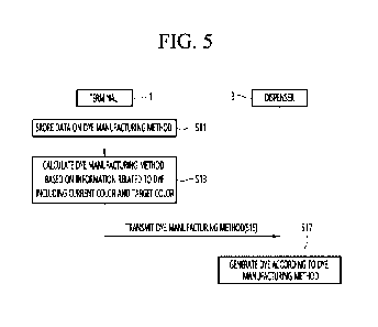
[000131] FIG. 5 is a flowchart illustrating a method of operating the cosmetic
manufacturing method calculation system according to an embodiment of the
present
disclosure.
[000132] The terminal 1 may store data on the dye manufacturing method in step
S11.
[000133] The terminal 1 may have previously stored data on the dye
manufacturing
method in the storage unit 19.
[000134] The terminal 1 may calculate the dye manufacturing method based on
dye-
related information including the current color and the target color in step
S13.
[000135] The terminal 1 receives the dye-related information including the
current color
and the target color through the input unit 13, and the control unit 11 may
calculate the
dye manufacturing method based on the dye-related information received through
the
input unit 13.
[000136] According to an embodiment, the terminal 1 may calculate the dye
manufacturing method by receiving dye-related information for manufacturing a
dye to
be used for the entire hair of the user.
18
Date Recue/Date Received 2022-09-12
CA 03175142 2022-09-12
[000137] According to another embodiment, the terminal 1 may divide the user's
hair into
a plurality of zones and receive dye-related information for manufacturing a
dye to be
used in each of the plurality of divided hair zones to calculate the dye
manufacturing
method in plural.
[000138] That is, the terminal 1 may provide a function of calculating the dye
manufacturing method for each hair zone. As described above, when the dye
manufacturing method is calculated for each hair zone, it is possible to
calculate
differently the dye manufacturing method for each hair zone, and accordingly,
it is
possible to manufacture a dye suitable for a state and characteristics of each
zone for
each hair zone, and thus there is an advantage that the quality of dying is
improved and
user satisfaction is increased. As a specific example, since the user's
previously dyed
hair has a different color and degree of damage between a zone close to the
scalp and a
zone close to the tip of the hair, when the entire hair is dyed with the same
dye, the case
of dyeing for each zone may be different. As another example, when there is a
user
who wants to dye two or more colors such as two-tone according to their taste,
it is
necessary to manufacture a different dye for each hair zone. In such a case,
there is an
advantage that the efficiency of manufacturing the dye is increased by
calculating the
dye manufacturing method for each hair zone.
[000139]
[000140] Next, with reference to FIG. 6, a method for a terminal according to
an
embodiment of the present disclosure to calculate a dye manufacturing method
will be
described.
[000141] FIG. 6 is a flowchart illustrating the method for the terminal
according to the
embodiment of the present disclosure to calculate the dye manufacturing
method. FIG.
6 may be a flowchart in which the step S13 of FIG. 5 is embodied.
[000142] The control unit 11 may determine whether a manufacturing command of
the
19
Date Recue/Date Received 2022-09-12
CA 03175142 2022-09-12
dye for each hair zone has been received in step S13.
[000143] The control unit 11 may receive an input from the user as to whether
to
manufacture or not to manufacture the dye for each hair zone and determine
whether to
manufacture or not to manufacture the dye for each hair zone according to the
received
input.
[000144]
[000145] FIG. 7 is a view illustrating an example of a method of determining
whether the
terminal according to the embodiment of the present disclosure has received a
command for manufacturing a dye for each hair zone.
[000146] The display unit 17 may display a screen for confirming whether to
manufacture
or not to manufacture the dye for each hair zone. For example, the display
unit 170
may display at least one of a message asking whether to manufacture or not to
manufacture the dye for each hair zone, a confirmation icon (e.g., `Yes'), and
a cancel
icon (e.g., `No').
[000147] The control unit 11 may determine whether the command for
manufacturing the
dye for each hair zone is received based on the input received through the
input unit 13
while the screen for confirming whether or not to manufacture the dye for each
hair
zone is displayed. For example, when receiving a command for selecting the
confirmation icon while being displayed on the screen as shown in FIG. 7, the
control
unit 11 may determine that the command for manufacturing the dye for each hair
zone
has been received, and when receiving the command for selecting the cancel
icon, the
control unit 11 may determine that the command for manufacturing the dye for
each
hair zone has not been received.
[000148] FIG. 6 will be described again.
[000149] When the command for manufacturing the dye for each hair zone is not
received,
the control unit 11 may receive an input of the current color in step S22 and
an input of
Date Recue/Date Received 2022-09-12
CA 03175142 2022-09-12
the target color in step S23.
[000150]
[000151] FIG. 8 is a view illustrating an example of a method for the terminal
according
to the embodiment of the present disclosure to receive an input of a current
color or a
target color.
[000152] As shown in FIG. 8, the control unit 11 may control the display unit
17 to
display a plurality of colors and receive the input of the current color or
the target color
through the command for selecting any one of the plurality of colors displayed
on the
display unit 17.
[000153] Meanwhile, according to an embodiment, the cosmetic manufacturing
method
calculation system may further include a scanner (not shown) and may receive
the input
of the current color through the scanner (not shown). The scanner (not shown)
may be
a device capable of measuring the color of hair. The scanner (not shown) may
be a
part of the terminal 1.
[000154] FIG. 6 will be described again.
[000155] When receiving the input of the current color and the target color,
the control
unit 11 may receive an input of sub-information including at least one of a
dyeing type,
a dye amount, a thickener, and an oxidizer in step S24.
[000156] The control unit 11 may or may not receive the input of the sub-
information.
That is, the user may or may not input the sub-information.
[000157] When the input of the sub-information is not received, the control
unit 11 may
calculate the dye manufacturing method for dyeing hair from the current color
to the
target color based on the data on the dye manufacturing method stored in the
storage
unit 19.
[000158] For example, when the current color is 4N and the target color is 5N,
the control
unit 11 may calculate the dye manufacturing method through a table as shown in
an
21
Date Recue/Date Received 2022-09-12
CA 03175142 2022-09-12
example of Table 1 below.
[000159] [Table 11
Dye cal u idge number
Starting Color Desired Color
1 2 3 4 5 6 7 8 9 10
4N 5N 10 20 30
[000160] Examples of sub-information include, but are not limited to, a dying
type, a dye
amount, a thickener option, and an oxidizer option, and the like.
[000161]
[000162] FIG. 9 is a view illustrating an example of a method for the terminal
according
to the embodiment of the present disclosure to receive an input of a dying
type, and FIG.
is a view illustrating an example of a method for the terminal according to
the
10 embodiment of the present disclosure to receive an input of a dye
amount, a thickener
option, an oxidizer option, and additional color option.
[000163] Referring to FIG. 9, the display unit 17 may display a plurality of
dyeing types,
and the control unit 11 may receive an input of a dyeing type through a
command for
selecting any one of the plurality of dyeing types.
[000164] Examples of dyeing types may include permanent color, combination
permanent
color & highlight, first demi-permanent color, second semi-permanent color,
gray
coverage, and chroma shine dying, but this is merely illustrative, and thus
the present
disclosure is not limited thereto.
[000165] That is, the input unit 13 may further receive an input of the dyeing
type, and
the control unit 11 may differently calculate the dye manufacturing method
according to
the dyeing type. When the current color and the target color are the same but
the
dyeing type is input differently, the control unit 11 may differently
calculate the dye
22
Date Recue/Date Received 2022-09-12
CA 03175142 2022-09-12
manufacturing method. For example, when the current color is 4N and the target
color
is 5N, which is the same for each type of dyeing, but the types of dyeing are
respectively different for the permanent color, the first demi-permanent
color, and the
second semi-permanent color, the control unit 11 may calculate the dye
manufacturing
method so that the dye material, the dyeing time, or the like is different as
shown in the
example of Table 2 below.
[000166] [Table 21
Type of Starting Desired Dye cal tlidge number
Total Timing
dyeing Color Color 1 2 3 4 5 6 7 8 9 10
Permanent
4N 5N 10 20 30 60 60min
Color
Demi-
Permanent 4N 5N 6.67 13.33 20 20 60 45min
Color
Semi-
Permanent 4N 5N 6.67 13.33 20 20 60 30min
Color
[000167] That is, when the current color and the target color are the same but
the dyeing
type is input differently, the control unit 11 may differently calculate the
dye
manufacturing method by adjusting at least one of the cartridge for
discharging the dye
material and the discharge amount, or may differently calculate the dye
manufacturing
method by determining the dyeing time using the dye.
[000168] Referring to FIG. 10, the display unit 17 may display 2 oz, 3 oz, 4
oz, 5 oz, and
6 oz, etc. as the dye amount (QUANTITY), and the control unit 170 may receive
an
23
Date Recue/Date Received 2022-09-12
CA 03175142 2022-09-12
input of the dye amount through a command for selecting any one of the
displayed 2 oz,
3 oz, 4 oz, 5 oz, 6 oz, etc.
[000169] That is, the input unit 13 may further receive an input of the dye
amount, and
the control unit 11 may differently calculate the dye manufacturing method by
adjusting
the discharge amount according to the dye amount. For example, when the
current
color is 4N and the target color is 5N, which is the same for each type of
dyeing, but the
dye amount is 2oz, 3oz, 4oz, 5oz, and 6oz, respectively, the control unit 11
may
differently calculate the dye manufacturing method as shown in the example in
Table 3
below.
[000170] [Table 31
Dye Starting Desired Dye cartridge number
Total Timing
amount Color Color 1 2 3 4 5 6 7 8 9 10
2oz 4N 5N 10 20 30 60
60min
3oz 4N 5N 15 30 45 90
60min
4oz 4N 5N 20 40 60
120 60min
5oz 4N 5N 25 50 75
150 60min
6oz 4N 5N 30 60 90
180 60min
[000171] In addition, the input unit 13 may further receive an input for
adding at least one
of a thickener and an oxidizer, and the control unit 11 may modify the dye
manufacturing method when receiving the input for adding the thickener or the
oxidizer.
That is, the control unit 11 may modify the dye manufacturing method so that
the
thickener or the oxidizer is added to the dye manufacturing method calculated
based on
the current color and the target color.
[000172]
24
Date Recue/Date Received 2022-09-12
CA 03175142 2022-09-12
[000173] As an example, the display unit 17 may display GEL and CREAM as a
thickener type, and the control unit 11 may receive an input of a thickener
option
through a command for selecting any one of the displayed GEL and CREAM. In
addition, when the thickener type is selected, the control unit 11 may
determine that the
input for adding the thickener is received. In this case, the control unit 11
may modify
the dye manufacturing method so that the thickener is added as shown in Table
4 below.
[000174] [Table 41
Dye cartridge number
Starting Desired Thi
Total Timing
Color Color 1 2 3 4 5 6 7
8 9 10 cke
ner
4N 5N 10 20 30 60
60min
add
thickene 4N 5N 10 20 30 3
63 60min
r
[000175] As another example, the display unit 17 may display 10, 20, 30
and 40 as the
oxidizer amount (VOLUME), and the control unit 11 may receive an input of an
oxidizer
option through a command for selecting any one of the displayed 10, 20, 30 and
40, etc.
When the oxidizer option is selected, the control unit 11 may determine that
an input for
adding an oxidizer is received. In this case, the control unit 11 may modify
the dye
manufacturing method so that the oxidizer is added as shown in Table 5 below.
In
addition, according to the embodiment, the type of the oxidizer may be two or
more.
[000176] [Table 51
Date Recue/Date Received 2022-09-12
CA 03175142 2022-09-12
Oxidizer Starting Desired
Oxidiz Oxidiz Total Timing
option Color Color 1 2 3 4 5 6 7 8 9 10
en 1 er 2
4N 5N 10 20 5 25 60 60min
4N 5N 10 20 15 15 60 60min
4N 5N 10 20 20 10 60 60min
4N 5N 10 20 30 0 60 60min
[000177] In addition, the control unit 11 may receive an option of
additional colors
(ADDITIVES). The display unit 17 may display an additional color option icon
(+
ADD ADDITIVES) through which an additional color may be input, and according
to a
5 command for selecting the additional color option icon, the control unit
11 may add a
dye material to develop a different color in addition to the dye material
included based
on the current color and the target color. Through this, there is an advantage
that the
hair designer may more easily manufacture the dye by easily adding other dye
materials
in addition to the dye materials automatically selected according to the
individual's
10 know-how.
[000178]
[000179] Meanwhile, since FIG. 10 is merely illustrative, it is
appropriate that the present
disclosure is not limited thereto.
[000180] FIG. 6 will be described again.
15 [000181] The control unit 11 may calculate the dye manufacturing method
based on at
least one of the current color, the target color, and the sub-information in
step S26.
[000182] The control unit 11 may calculate the dye manufacturing method
corresponding
to the input current color, target color, and the sub-information based on the
data on the
26
Date Recue/Date Received 2022-09-12
CA 03175142 2022-09-12
dye manufacturing method. Since the calculation method of the dye
manufacturing
method has been described through Table 1 to Table 5, a redundant description
will be
omitted.
[000183] However, the above Table 1 to Table 5 are also merely illustrative,
and the
control unit 11 may calculate the dye manufacturing method based on at least
one of the
current color, target color, and the sub-information in various ways.
[000184] When the control unit 11 calculates the dye manufacturing method, the
control
unit 11 may display the dye manufacturing method as shown in FIG. 11.
[000185] FIG. 11 is a view illustrating an example of a method for the
terminal according
to the embodiment of the present disclosure to display a method of
manufacturing a
calculated dye.
[000186] The display unit 15 may display the calculated dye manufacturing
method.
Referring to the example of FIG. 11, the display unit 15 may display the type
and
discharge amount (3/4 oz 4RV + 1/4 oz 4RR + 1 oz 20 volume) of the dye
material, and
a recommended temperature when the dye is used. The recommended temperature
may include a temperature (room temp) and time information of a space where
the
dyeing is made, whether or not to heat with additional heat (with low heat),
and time
information.
[000187]
[000188] Meanwhile, in step S20, when receiving the command for manufacturing
the
dye for each hair zone, the control unit 11 may receive the current color, the
target color,
and the sub-information for each hair zone.
[000189]
[000190] Meanwhile, the control unit 11 may receive at least one of an input
for selecting
the number of hair zones and an input for selecting a hair zone before
receiving the dye
related information.
27
Date Recue/Date Received 2022-09-12
CA 03175142 2022-09-12
[000191] The hair zone may refer to each zone in the hair that is divided so
that different
dyes are used.
[000192] The number of hair zones may refer to the number of zones in the hair
divided
so that different dyes are used.
[000193] The hair zone and the number of hair zones may be preset or may be
set by the
user.
[000194]
[000195] First, a method of receiving an input for selecting the hair zone
will be described.
[000196] FIG. 12 is a view illustrating an example of a method for the
terminal according
to the embodiment of the present disclosure to receive a command for selecting
the
number of hair zones.
[000197] The display unit 17 may display a screen for selecting the number of
hair zones
as shown in FIG. 12. The control unit 11 may set the number of hair zones to 2
when
receiving a command for selecting 2 on the screen and set the number of hair
zones to 4
when receiving a command for selecting 4 on the screen. Meanwhile, the example
of
FIG. 12 illustrates that the display unit 17 displays that the number of hair
zones is
selected as any one of 1 to 4, but this is merely illustrative for convenience
of
description, and thus the present disclosure is not limited thereto. That is,
the number
of hair zones to which the control unit 11 may receive input may vary.
[000198] As described above, the control unit 11 may set the number of hair
zones by
receiving the command for selecting the number of hair zones.
[000199]
[000200] The control unit 11 may receive an input for selecting a hair zone
after setting
the number of hair zones.
[000201] According to a first embodiment, the display unit 17 may display an
image
including hair, and the control unit 11 may receive an input for selecting a
hair zone
28
Date Recue/Date Received 2022-09-12
CA 03175142 2022-09-12
through the image displayed on the display unit 17.
[000202] FIGS. 13 to 14 are views illustrating an example of a method for a
terminal
according to an embodiment of the present disclosure to receive a command for
selecting a hair zone.
[000203] The display unit 17 may display an image including hair. In this
case, the
image may be an image previously stored in the storage unit 19 or an image
received
from the outside through the communication unit 15. Alternatively, the image
may be
an image of a user captured through a camera (not shown) provided in the
terminal 1.
[000204] The control unit 11 may display at least one dividing line for
dividing the hair
zone together with the image. The dividing line may be a straight line as
shown in
FIG. 13 or FIG. 14, but this is merely illustrative. That is, the dividing
line may be a
curved line unlike FIG. 13 or FIG. 14, and in this case, the user may more
freely select
the hair zone. In FIGS. 13 and 14, it is assumed that the dividing line is a
straight line.
[000205] The control unit 11 may control the display unit 17 to display
horizontal
dividing lines 41 and 42 on the image as shown in FIG. 13 or to display
vertical
dividing lines 51 and 52 on the image as shown in FIG. 14.
[000206] The control unit 11 may control the display unit 17 to further
display a line
change icon 40 when displaying the horizontal dividing lines 41 and 42 on the
image.
When receiving a command for selecting the line change icon 40, the control
unit 11
may change the horizontal dividing lines 41 and 42 displayed on the image to
the
vertical dividing lines 51 and 52.
[000207] In addition, the control unit 11 may receive a command for dragging
and
dropping in one direction by selecting any one of the horizontal dividing
lines 41 and 42.
Accordingly, the control unit 11 may change a position of the selected
horizontal
dividing line to a dropped position. When the positions of the horizontal
dividing lines
41 and 42 are determined, the control unit 11 may set the hair zone based on
the
29
Date Recue/Date Received 2022-09-12
CA 03175142 2022-09-12
horizontal dividing lines 41 and 42.
[000208] Similarly, the control unit 11 may control the display unit 17
to further display a
line change icon 50 when displaying the vertical dividing lines 51 and 52 on
the image.
When receiving a command for selecting the line change icon 50, the control
unit 11
may change the vertical dividing lines 51 and 52 displayed on the image to the
horizontal dividing lines 41 and 42.
[000209] In addition, the control unit 11 may receive a command for dragging
and
dropping in one direction by selecting any one of the vertical dividing lines
51 and 52.
Accordingly, the control unit 11 may change a position of the selected
vertical dividing
line to a dropped position. When the positions of the vertical dividing lines
51 and 52
are determined, the control unit 11 may set the hair zone based on the
vertical dividing
lines 51 and 52.
[000210] As described above, according to the first embodiment, there is an
advantage
that the user may easily select the hair zone with only the drag and drop
command of
the dividing line displayed on the display unit 17.
[000211] Meanwhile, when calculating a cosmetic manufacturing method other
than a dye,
the terminal 1 may display a dividing line for dividing a face other than the
hair zone
into a plurality of face zones. That is, the terminal 1 may set the number of
face zones,
display the dividing line to classify the face zones according to the set
number of face
zones, and classify the face zones by adjusting the position of the dividing
line.
[000212] According to this, the terminal 1 may differently calculate the
cosmetic
manufacturing method for each face zone. Therefore, the terminal 1 may
differently
calculate a foundation manufacturing method for each face zone, and in this
case, there
is an advantage that cosmetics having different colors and textures may be
manufactured for each face zone. In addition, the terminal 1 may differently
calculate
a manufacturing method of basic cosmetics for each face zone, and in this
case, there is
Date Recue/Date Received 2022-09-12
CA 03175142 2022-09-12
an advantage that cosmetics having different functional ingredients may be
manufactured for each face zone. That is, there is an advantage that the user
may
easily receive necessary cosmetics according to a state of each face zone.
[000213]
[000214] According to a second embodiment, the display unit 17 may display a
plurality
of previously divided hair zones, and the control unit 11 may receive an input
for
selecting the hair zone through a command for selecting at least one of the
plurality of
hair zones.
[000215] Meanwhile, the control unit 11 may receive an input for selecting the
hair zone
through various methods other than the above-described embodiments. In
addition,
according to an embodiment, since the hair zones are predetermined, an input
for
separately selecting the hair zone may not be received even when a command for
manufacturing the dye for each hair zone is received.
[000216]
[000217] When the hair zone is determined, the control unit 11 may receive an
input of
the current color for each hair zone in step S32 and may receive an input of
the target
color for each hair zone in step S33.
[000218] FIG. 15 is a view illustrating an example of a method for the
terminal according
to the embodiment of the present disclosure to receive a command for selecting
a
current color for each hair zone, and FIG. 16 is a view illustrating an
example of a
method for the terminal according to the embodiment of the present disclosure
to
receive a command for selecting a target color for each hair zone.
[000219] As shown in FIGS. 15 and 16, the control unit 11 may control the
display unit
17 to display a screen for receiving the command for selecting the current
color and the
command for selecting the target color for each hair zone. For example, the
control
unit 11 may set the number of hair zones to three, and when three hair zones
are set, the
31
Date Recue/Date Received 2022-09-12
CA 03175142 2022-09-12
control unit 11 may receive the command for selecting the current color and
the
command for selecting the target color for each of the three hair zones.
[000220] A method of receiving the command for selecting the current color and
the
command for selecting the target color is the same as described in steps S22
and S23,
and thus a redundant description will be omitted.
[000221]
[000222] In addition, the control unit 11 may receive an input of sub-
information
including at least one of a dying type, a dye amount, a thickener option, an
oxidizer
option, and an additional color option for each hair zone (S34).
[000223] FIG. 17 is a view illustrating an example of a method for the
terminal according
to the embodiment of the present disclosure to receive an input of a dying
type for each
hair zone.
[000224] As shown in FIG. 17, the control unit 11 may control the display unit
17 to
display a plurality of hair zones ZONE 1, ZONE 2, and ZONE 4 and may receive
an
input of a dying type for each of the plurality of hair zones.
[000225] Similarly, although not shown in the drawings, the control
unit 11 may receive
an input of a dye amount, a thickener option, an oxidizer option, or an
additional color
option for each of the plurality of hair zones. Specifically, as shown in FIG.
10, the
control unit 11 may receive an input of sub-information for each hair zone by
displaying
a screen for receiving the input of the dye amount, the thickener option, the
oxidizer
option, and the additional color option for each hair zone.
[000226] As described above, the control unit 11 may select the dying type,
the dye
amount, the thickening option, the oxidizer option, and the additional color
option for
each hair zone.
[000227]
[000228] The control unit 11 may calculate the dye manufacturing method based
on at
32
Date Recue/Date Received 2022-09-12
CA 03175142 2022-09-12
least one of the current color, the target color, and the sub-information for
each hair
zone in step S36.
[000229] For example, when calculating the dye manufacturing method for each
hair zone,
the control unit 11 may calculate the dye manufacturing method so that the
discharge
amount of the dye material is different depending on the hair zone or may
differently
calculate the dye manufacturing method by differently determining a dyeing
time
depending on the hair zone.
[000230] For example, the control unit 11 may calculate a dye manufacturing
method in
which the oxidizer amount is a first amount and the dyeing time is a first
time for a dye
to be used in a first hair zone close to the scalp and may calculate a dye
manufacturing
method in which the oxidizer amount is a second amount less than the first
amount and
the dyeing time is a second time shorter than the first time for a dye to be
used in a
second hair zone close to the tip of the hair. In this case, since the
oxidizer is less
added to the zone close to the tip of the hair which is relatively thin and
severely
damaged than the zone close to the scalp, and the dye manufacturing method is
calculated so that the dyeing time is short, there is an advantage that a
color developed
throughout the hair is similar and the dye may be calculated for each zone so
that the
degree of damage to the tip of the hair is minimized.
[000231] In addition, since the control unit 11 calculates the dye
manufacturing method
for each hair zone when receiving the command for manufacturing the dye for
each hair
zone, the display unit 17 may display the calculated dye manufacturing method
in plural
unlike FIG. 11.
[000232] In addition, the method of calculating the dye manufacturing method
for each
hair zone is slightly different from that of step S26 in that it is calculated
and displayed
for each hair zone and the rest are the same, and thus a redundant description
will be
omitted.
33
Date Recue/Date Received 2022-09-12
CA 03175142 2022-09-12
[000233]
[000234] According to an embodiment, when the dye manufacturing method is
calculated,
the control unit 11 may control the display unit 17 to display a simulation
based on the
calculated dye manufacturing method. The simulation may be a prediction result
when a dye manufactured according to the calculated dye manufacturing method
is used.
[000235] FIG. 18 is a view illustrating an example of a method for the
terminal according
to the embodiment of the present disclosure to display a simulation.
[000236] The control unit 11 may control the display unit 17 to display the
simulation
according to the calculated dye manufacturing method.
[000237] According to an embodiment, the control unit 11 may control the
display unit 17
to display the simulation after the current color, the target color, and the
sub-
information are all selected.
[000238] According to another embodiment, the control unit 11 may control the
display
unit 17 to display the simulation after the current color and the target color
are selected
and before the sub-information is selected. In this case, the user may correct
the target
color after confirming the simulation and select the sub-information based on
the
simulation even when selecting the sub-information, and thus there is an
advantage that
the selection of the sub-information is easy.
[000239] According to still another embodiment, the control unit 11 may
control the
display unit 17 to primarily display the simulation after the current color
and the target
color are selected, and to secondarily display the simulation after the sub-
information is
selected.
[000240] In addition, the control unit 11 may control the display unit
17 to display the
simulation regardless of whether or not the dye for each hair zone is
manufactured.
That is, the control unit 11 may control the display unit 17 to display all
simulations
when calculating the dye manufacturing method without dividing the hair zone
and
34
Date Recue/Date Received 2022-09-12
CA 03175142 2022-09-12
when calculating the dye manufacturing method by dividing the hair zone.
[000241]
[000242] FIG. 5 will be described again.
[000243] When the dye manufacturing method is calculated, the control unit 11
may
transmit the calculated dye manufacturing method to the dispenser 3 in step
S15.
[000244] The dispenser 3 may receive the dye manufacturing method from the
terminal 1
and may generate the dye according to the received dye manufacturing method in
step
S17.
[000245] When the dispenser 3 receives the dye manufacturing method from the
terminal
1, the dispenser 3 may generate the dye according to the received dye
manufacturing
method.
[000246] When the dispenser 3 receives the dye manufacturing method in plural
from the
terminal 1, the dispenser 3 may manufacture the dye according to each of the
plurality
of dye manufacturing methods. That is, in this case, the dispenser 3 may
manufacture
the dye for each hair zone.
[000247] FIG. 19 is a view illustrating an example of a screen displayed when
the
dispenser according to an embodiment of the present disclosure receives a
method of
manufacturing a dye for each hair zone.
[000248] The dispenser 3 may control the display unit (not shown) to display
the dye
manufacturing method received from the terminal 1. For example, when the
dispenser
3 receives the dye manufacturing method in plural from the terminal 1, the
dispenser 3
may control the display unit (not shown) to display the plurality of dye
manufacturing
methods.
[000249] The screen of FIG. 19 may be an example of a screen on which the
dispenser 3
displays the plurality of dye manufacturing methods. As shown in the screen of
FIG.
19, the display unit (not shown) of the dispenser 3 may respectively display
the dye
Date Recue/Date Received 2022-09-12
CA 03175142 2022-09-12
manufacturing method calculated for each hair zone. Referring to the example
of FIG.
19, the display unit (not shown) of the dispenser 3 may display each of a
method of
manufacturing a first dye for manufacturing 2 oz of a dye for dyeing a hair of
a first hair
zone (ZONE 1) from color 7A to color 9B, a method of manufacturing a second
dye for
manufacturing 2 oz of a dye for dyeing a hair of a second hair zone (ZONE 2)
from
color 7A to color 11B, and a method of manufacturing a third dye for
manufacturing 2
oz of a dye for dyeing a hair of a third hair zone (ZONE3) from 6B color to 8C
color.
The control unit 31 may generate a dye according to a method of manufacturing
the
selected dye when receiving a discharge command (a command for selecting a
'DISPENSE' icon) after any one of a plurality of displayed dye manufacturing
methods
is selected. For example, when the control unit 31 receives a discharge
command for
all of the three dyeing methods shown in FIG. 19, the control unit 31 may
drive the
driving unit 37 to discharge the three dyes to each container (not shown).
[000250]
[000251] The present disclosure described above may be implemented as computer-
readable codes in a medium on which a program is recorded. The computer-
readable
medium includes all kinds of recording devices in which data readable by a
computer
system is stored. Examples of the computer-readable medium include a hard disk
drive (HDD), a solid state disk (SSD), a silicon disk drive (SDD), a ROM, a
RAM, a
CD-ROM, a magnetic tape, a floppy disk, and an optical data storage, etc. In
addition,
the computer may include the control unit of the terminal 1 or the control
unit 31 of the
dispenser 3. Therefore, the above detailed description should not be construed
in a
limiting sense in all respects, and should be considered as examples. The
scope of the
present invention should be determined by rational interpretation of the
appended
claims, and encompasses all alterations falling within the equivalent scope of
the
appended claims.
36
Date Recue/Date Received 2022-09-12
CA 03175142 2022-09-12
[000252] The above description is merely illustrative of the technical
spirit of the present
invention, and various modifications and variations will be possible without
departing
from the essential characteristics of the present invention by those skilled
in the art to
which the present invention pertains.
[000253] Therefore, the embodiments disclosed in the present invention are not
intended
to limit the technical spirit of the present invention, but to explain, and
the scope of the
technical spirit of the present invention is not limited by these embodiments.
[000254] The protection scope of the present invention should be construed by
the
following claims, and all technical ideas within the equivalent range should
be
construed as being included in the scope of the present invention.
[000255]
[000256]
20
37
Date Recue/Date Received 2022-09-12