Note: Descriptions are shown in the official language in which they were submitted.
CA 03175735 2022-09-16
WO 2021/074039
PCT/EP2020/078477
MOTOR FLUID TRANSFER SYSTEM AND METHOD
BACKGROUND
[0001] Many motors use one or more fluids for their operation. Such fluids are
often liquids.
During operation, fluids may be circulated through a motor to impart various
benefits. Often, to
ensure that sufficient fluid is available to continuously cycle the fluid
through the motor, the
fluid is continuously returned to a fluid receptacle of the motor, from which
it can be drawn for
further circulation.
[0002] Fluids circulated through a motor may require periodic changing. Such
fluid change
may involve draining the fluid from the motor, which may involve time
consuming and costly
maintenance.
OVERVIEW
[0003] Disclosed herein are methods and systems for regulating fluid in a
fluid receptacle.
Beneficially, the methods and systems use a fluid container to receive fluid
from the fluid
receptacle and to return the fluid to the fluid receptacle.
[0004] Thus, in a first aspect, the present disclosure provides a method for
controlling a fluid
drain interval in a motor, the method comprising:
containing a first volume of fluid in a reservoir of a fluid container that is
in fluid
communication with a fluid receptacle of a motor;
containing a second volume of fluid in the fluid receptacle;
transferring a first quantity of fluid from the fluid receptacle to the
reservoir of the fluid
container so as to mix the first quantity of fluid from the fluid receptacle
with the
volume of fluid in the reservoir of the fluid container; and
1
CA 03175735 2022-09-16
WO 2021/074039 PCT/EP2020/078477
transferring a second quantity of fluid from the reservoir back to the fluid
receptacle.
[0005] In another embodiment of the method for controlling a fluid drain
interval, the fluid is a
lubricant.
[0006] In another embodiment of the method for controlling a fluid drain
interval, the method
further includes:
receiving information indicative of a duration of operation of the motor since
transferring the second quantity of fluid from the reservoir back to the fluid
receptacle, and
in response to the duration of operation of the motor reaching a predetermined
threshold duration, transferring a third quantity of fluid from the fluid
receptacle to the reservoir
of the fluid container so as to mix the third quantity of fluid from the fluid
receptacle with fluid
in the reservoir of the fluid container, and transferring a fourth quantity of
fluid from the
reservoir back to the fluid receptacle.
[0007] In another embodiment of the method for controlling a fluid drain
interval, the method
further includes:
receiving information indicative of a duration of operation of the motor since
a previous
fluid change, and
in response to the duration of operation of the motor being below a
predetermined
threshold duration, transferring a third quantity of fluid from the fluid
receptacle to the reservoir
of the replaceable fluid container so as to mix the third quantity of fluid
from the fluid receptacle
with fluid in the reservoir of the replaceable fluid container, and
transferring a fourth quantity of
fluid from the reservoir back to the fluid receptacle.
2
CA 03175735 2022-09-16
WO 2021/074039 PCT/EP2020/078477
[0008] In another embodiment of the method for controlling a fluid drain
interval, the
information indicative of a duration of operation of the motor includes at
least one of an ignition
key position and a battery voltage being above a predetermined threshold
voltage.
[0009] In another embodiment of the method for controlling a fluid drain
interval, the method
further includes: in response to receiving an input from a user, initiating
the transferring the first
quantity of fluid from the fluid receptacle to the reservoir of the fluid
container.
[0010] In another embodiment of the method for controlling a fluid drain
interval, the first
quantity of fluid and the second quantity of fluid are transferred using a
transfer pump.
[0011] In another embodiment of the method for controlling a fluid drain
interval, transferring
the first quantity of fluid includes operating the transfer pump according to
a predetermined
control trajectory.
[0012] In another embodiment of the method for controlling a fluid drain
interval, the
predetermined control trajectory includes a predetermined number of pump
revolutions.
[0013] In another embodiment of the method for controlling a fluid drain
interval, the method
further includes receiving information indicative of an orientation of the
fluid receptacle, and
wherein the transferring the first quantity of fluid from the fluid receptacle
to the reservoir is
carried out in response to the orientation of the fluid receptacle being
substantially level.
[0014] In another embodiment of the method for controlling a fluid drain
interval, the first
quantity of fluid and the second quantity of fluid have the same volume.
[0015] In another embodiment of the method for controlling a fluid drain
interval, the first
quantity of fluid has a greater volume than the second quantity of fluid.
3
CA 03175735 2022-09-16
WO 2021/074039 PCT/EP2020/078477
[0016] In another embodiment of the method for controlling a fluid drain
interval, a volume of
the first quantity of fluid is in a range from 10% to 50% of the volume of the
fluid receptacle.
[0017] In a second aspect, the present disclosure provides a non-transitory
computer readable
medium, having stored thereon, instructions that when executed by a computing
device, cause a
computing device to perform operations comprising the steps of the method of
controlling a fluid
drain interval in a motor according to the disclosure.
[0018] In a third aspect, the present disclosure provides a fluid transfer
system for controlling a
fluid drain interval of a motor comprising:
a replaceable fluid container housing a fluid reservoir;
a fluid line configured to provide fluid communication between the fluid
reservoir and a
fluid receptacle of the motor;
a transfer pump configured to pump fluid through the fluid line between the
fluid
reservoir of the replaceable fluid container and the fluid receptacle; and
a controller configured to perform operations comprising the steps of the
method of
controlling a fluid drain interval in a motor according to the disclosure.
[0019] In another embodiment of the fluid transfer system for controlling a
fluid drain interval,
the controller comprises at least one memory and at least one processor,
wherein the at least one
processor executes instructions stored in the at least one memory so as to
carry out the
operations.
[0020] In another embodiment of the fluid transfer system for controlling a
fluid drain interval,
the controller comprises at least one of: an application-specific integrated
circuit (ASIC) or a
field-programmable gate array (FPGA).
4
CA 03175735 2022-09-16
WO 2021/074039 PCT/EP2020/078477
[0021] In another embodiment of the fluid transfer system for controlling a
fluid drain interval,
the transfer pump is a bidirectional transfer pump.
[0022] In another embodiment of the fluid transfer system for controlling a
fluid drain interval,
the system further comprises the motor including the fluid receptacle.
[0023] In another embodiment of the fluid transfer system for controlling a
fluid drain interval,
the motor does not include a level sensor for measuring a level of fluid in
the fluid receptacle.
[0024] In a fourth aspect, the present disclosure provides a method for
controlling the volume
of fluid in a fluid receptacle, the method comprising:
containing a first volume of fluid in a fluid receptacle of a motor;
transferring fluid from the fluid receptacle to a reservoir of a fluid
container so as to
evacuate the fluid receptacle; and
transferring a predetermined quantity of fluid from the reservoir back to the
fluid
receptacle.
[0025] In another embodiment of the method for controlling the volume of fluid
in the fluid
receptacle, the fluid is a lubricant.
[0026] In another embodiment of the method for controlling the volume of fluid
in the fluid
receptacle, the method further includes:
receiving information indicative of a duration of operation of the motor since
transferring
the predetermined quantity of fluid from the reservoir back to the fluid
receptacle, and
in response to the duration of operation of the motor reaching a predetermined
threshold duration, transferring fluid from the fluid receptacle of the motor
to the reservoir of the
CA 03175735 2022-09-16
WO 2021/074039 PCT/EP2020/078477
replaceable fluid container so as to again evacuate the fluid receptacle, and
transferring another
predetermined quantity of fluid from the reservoir back to the fluid
receptacle.
[0027] In another embodiment of the method for controlling the volume of fluid
in the fluid
receptacle, the information indicative of a duration of operation of the motor
includes at least one
of an ignition key position and a battery voltage being above a predetermined
threshold voltage.
[0028] In another embodiment of the method for controlling the volume of fluid
in the fluid
receptacle, the fluid is transferred using a transfer pump.
[0029] In another embodiment of the method for controlling the volume of fluid
in the fluid
receptacle, the transferring the predetermined quantity of fluid from the
reservoir back to the
fluid receptacle includes operating the transfer pump according to a
predetermined control
trajectory.
[0030] In another embodiment of the method for controlling the volume of fluid
in the fluid
receptacle, the predetermined control trajectory includes a predetermined
number of pump
revolutions.
[0031] In another embodiment of the method for controlling the volume of fluid
in the fluid
receptacle, the method further comprises receiving information indicative of
an orientation of the
fluid receptacle, and wherein the transferring the fluid from the fluid
receptacle to the reservoir
so as to evacuate the fluid receptacle is carried out in response to the
orientation of the fluid
receptacle being substantially level.
[0032] In a fifth aspect, the present disclosure provides a non-transitory
computer readable
medium, having stored thereon, instructions that when executed by a computing
device, cause
6
CA 03175735 2022-09-16
WO 2021/074039 PCT/EP2020/078477
the computing device to perform operations comprising the steps of the method
for controlling
the volume of fluid in the fluid receptacle of the disclosure.
[0033] In a sixth aspect, the present disclosure provides a fluid transfer
system for controlling
the volume of fluid in a fluid receptacle comprising:
a replaceable fluid container housing a fluid reservoir;
a fluid line configured to provide fluid communication between the fluid
reservoir and a
fluid receptacle of the motor;
a transfer pump configured to pump fluid through the fluid line between the
fluid
reservoir of the replaceable fluid container and the fluid receptacle; and
a controller configured to perform operations comprising the steps of the
method for
controlling the volume of fluid in a fluid receptacle of the disclosure.
[0034] In another embodiment of the fluid transfer system for controlling the
volume of fluid
in the fluid receptacle, the controller comprises at least one memory and at
least one processor,
wherein the at least one processor executes instructions stored in the at
least one memory so as to
carry out the operations.
[0035] In another embodiment of the fluid transfer system for controlling the
volume of fluid
in the fluid receptacle, the controller comprises at least one of: an
application-specific integrated
circuit (ASIC) or a field-programmable gate array (FPGA).
[0036] In another embodiment of the fluid transfer system for controlling the
volume of fluid
in the fluid receptacle, the transfer pump is a bidirectional transfer pump.
7
CA 03175735 2022-09-16
WO 2021/074039 PCT/EP2020/078477
[0037] In another embodiment of the fluid transfer system for controlling the
volume of fluid
in the fluid receptacle, the fluid transfer system further comprises the motor
including the fluid
receptacle.
[0038] In another embodiment of the fluid transfer system for controlling the
volume of fluid
in the fluid receptacle, the motor does not include a level sensor for
measuring a level of fluid in
the fluid receptacle.
[0039] These as well as other aspects, advantages, and alternatives, will
become apparent to
those of ordinary skill in the art by reading the following detailed
description.
BRIEF DESCRIPTION OF THE DRAWINGS
[0040] The accompanying drawings are included to provide a further
understanding of the
methods and devices of the disclosure, and are incorporated in and constitute
a part of this
specification. The drawings are not necessarily to scale, and sizes of various
elements may be
distorted for clarity. The drawings illustrate one or more embodiment(s) of
the disclosure, and
together with the description serve to explain the principles and operation of
the disclosure. In
the drawings, similar symbols typically identify similar components, unless
context dictates
otherwise.
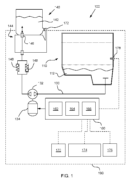
[0041] FIG. 1 is a schematic perspective view of a fluid system including a
motor according to
an example embodiment;
[0042] FIG. 2 is a flow chart illustrating a method according to an example
embodiment; and
[0043] FIG. 3 is a flow chart illustrating a method according to another
example embodiment.
8
CA 03175735 2022-09-16
WO 2021/074039 PCT/EP2020/078477
DETAILED DESCRIPTION
[0044] Example and systems are described herein. It should be understood that
the words
"example" and "exemplary" are used herein to mean "serving as an example,
instance, or
illustration." Any embodiment or feature described herein as being an
"example" or
"exemplary" is not necessarily to be construed as preferred or advantageous
over other
embodiments or features. Other embodiments may be utilized, and other changes
may be made,
without departing from the scope of the subject matter presented herein.
[0045] The example embodiments described herein are not meant to be limiting.
It will be
readily understood that the aspects of the present disclosure, as generally
described herein, and
illustrated in the figures, can be arranged, substituted, combined, separated,
and designed in a
wide variety of different configurations, all of which are explicitly
contemplated herein.
[0046] As used herein, with respect to measurements, "about" means +/- 5 %.
[0047] Unless otherwise indicated, the terms "first," "second," etc. are used
herein merely as
labels, and are not intended to impose ordinal, positional, or hierarchical
requirements on the
items to which these terms refer. Moreover, reference to, e.g., a "second"
item does not require
or preclude the existence of, e.g., a "first" or lower-numbered item, and/or,
e.g., a "third" or
higher-numbered item.
[0048] Reference herein to "one embodiment" or "one example" means that one or
more
feature, structure, or characteristic described in connection with the example
is included in at
least one implementation. The phrases "one embodiment" or "one example" in
various places in
the specification may or may not be referring to the same example.
9
CA 03175735 2022-09-16
WO 2021/074039 PCT/EP2020/078477
[0049] As used herein, a system, apparatus, device, structure, article,
element, component, or
hardware "configured to" perform a specified function is indeed capable of
performing the
specified function without any alteration, rather than merely having potential
to perform the
specified function after further modification. In other words, the system,
apparatus, structure,
article, element, component, or hardware "configured to" perform a specified
function is
specifically selected, created, implemented, utilized, programmed, and/or
designed for the
purpose of performing the specified function. As used herein, "configured to"
denotes existing
characteristics of a system, apparatus, structure, article, element,
component, or hardware which
enable the system, apparatus, structure, article, element, component, or
hardware to perform the
specified function without further modification. For purposes of this
disclosure, a system,
apparatus, structure, article, element, component, or hardware described as
being "configured to"
perform a particular function may additionally or alternatively be described
as being "adapted
to" and/or as being "operative to" perform that function.
[0050] In the following description, numerous specific details are set forth
to provide a
thorough understanding of the disclosed concepts, which may be practiced
without some or all of
these particulars. In other instances, details of known devices and/or
processes have been
omitted to avoid unnecessarily obscuring the disclosure. While some concepts
will be described
in conjunction with specific examples, it will be understood that these
examples are not intended
to be limiting.
[0051] The methods and systems described herein are adapted for transferring
fluid from a
fluid receptacle of a motor to a reservoir of a fluid container that is in
fluid communication with
the fluid receptacle. The methods and systems further include returning the
fluid to the fluid
receptacle from the reservoir of the fluid container.
CA 03175735 2022-09-16
WO 2021/074039
PCT/EP2020/078477
[0052] In some embodiments, the motor may be an internal combustion engine and
the fluid
receptacle may a sump of the engine. Accordingly, in some embodiments the
fluid may be a
lubricant that is configured to lubricate moving parts of the motor. For
example, the fluid may
be an engine lubricant. In other embodiments, the motor may be an electric
motor and the fluid
receptacle may contain fluid used with the electric motor. For example, the
fluid may be a
coolant or a lubricant used in the electric motor. Moreover, methods of the
invention may also
be applicable to other fluids used in other machinery, such as coolants used
with batteries.
[0053] With reference to the Figures, FIG. 1 shows a fluid transfer system 100
for moving
fluid between a fluid receptacle of a motor and a reservoir of a fluid
container. Fluid transfer
system 100 includes a motor 110 with a fluid receptacle 112 and a reservoir
142 of a fluid
container 140. The fluid receptacle 112 is in fluid communication with the
reservoir 142 via
fluid line 130. A fluid pump 132 may be disposed in the fluid line 130 that is
operable to
transfer the fluid from the fluid receptacle 112 of the motor 110 to the
reservoir 142 in the fluid
container 140 and from the reservoir 142 back to the fluid receptacle 112.
[0054] In some embodiments, the fluid may be a lubricant in the form of a
lubricating oil that
includes at least one base stock and at least one lubricating oil additive.
Suitable base stocks
include bio-derived base stocks, mineral oil derived base stocks, synthetic
base stocks, and semi
synthetic base stocks. Suitable lubricating oil additives, for example motor
lubricating oil
additives, may be organic and/or inorganic compounds. In some embodiments, the
lubricating
oil includes a range of 60% to 90% by weight base stock and 40% to 10% by
weight additives.
The lubricating oils may be mono-viscosity grade or multi-viscosity grade
motor lubricating oil.
Examples of suitable lubricating oil include single purpose lubricating oil
and multipurpose
lubricating oil.
11
CA 03175735 2022-09-16
WO 2021/074039 PCT/EP2020/078477
[0055] The methods and systems of the disclosure may be used in or with a wide
variety of
different machines that utilize a motor, and the fluid transfer system may be
part of or associated
with the machine. For example, in the fluid transfer system 100 shown in FIG.
1, the motor 112
is part of a machine 190. The machine 190 may have any of a variety of
different forms. For
example, the machine 190 may be a small or mid-sized apparatus or tool that is
powered by an
engine or electric motor, such as a lawnmower, a generator, or a compressor.
In some
embodiments, the machine 190 may be a hand tool, such as a chainsaw, hedge
trimmer, or leaf
blower. Further, the machine 190 may be a vehicle, such as a car, a boat, a
motorcycle, a train or
an airplane, for example. The foregoing machines are merely examples, and the
methods and
systems described herein can also be used with a variety of other machines.
[0056] In some embodiments, the motor 110 may be a small engine or an engine
that might not
have various electronic systems, including sensors and communication
interfaces. For example,
the motor might not have a fluid level sensor associated with the fluid
receptacle 112.
[0057] In some embodiments, the fluid container 140 may be a replaceable fluid
container that
is adapted to be coupled to the motor 110 via a dock 144 or other temporary
fluid coupling
configuration. The dock 144 may be a part of the machine 190 so that the fluid
container 140
can be connected with and disconnected with the fluid receptacle 112 and other
parts of the
machine 190 by inserting and removing the fluid container 140 from the dock
144. The dock
144 may include one or more fluid port couplings 146 that are configured to
receive
corresponding fluid port couplings of the fluid container 140 that are in
fluid communication
with the reservoir 140.
[0058] In some embodiments, the fluid container 140 is an oil cell that is
adapted for providing
fresh oil to the motor 110 during an oil change and removing spent oil from
the motor after it has
12
CA 03175735 2022-09-16
WO 2021/074039 PCT/EP2020/078477
been used. Accordingly, the fluid reservoir 142 may hold lubricating oil, for
example, motor
lubricating oil. In particular, a new oil cell 140 can provide fresh,
refreshed or unused
lubricating oil which may conveniently replace a fluid container holding used
or spent
lubricating oil. During such an oil change operation, the reservoir 142 of the
fluid container 140
may retain a reserve quantity of fluid for use in the methods described
herein.
[0059] In some embodiments, the fluid pump 132 may be a rotary pump. For
example, the
fluid pump may be a gear pump, trochoid pump, or vane pump. In some
embodiments, the fluid
pump 132 may include a bidirectional fluid pump that is configured to pump the
fluid in either
direction. In other embodiments, the fluid transfer system 100 may include two
pumps that
respectively pump the fluid from the fluid receptacle 112 to the reservoir 142
and from the
reservoir 142 to the fluid receptacle 112. Still, in some embodiments, the
fluid line 130 between
the fluid receptacle 112 and the reservoir 142 may include valve arrangements
to reroute the
flow path so that the fluid pump 132 can transfer the fluid in either
direction. The term pump, as
used herein, includes any device that uses energy to move a fluid. For
example, the pump can be
formed by any actuator or mechanism that moves fluid, such as rotary, piston
or other pumps.
[0060] FIG. 2 shows an example embodiment of a method 200 of transferring
fluid between a
fluid receptacle of a motor and a reservoir of a fluid container. As shown by
block 202, the
method 200 may involve containing a first volume of fluid in a reservoir of a
fluid container that
is in fluid communication with a fluid receptacle of a motor. Further, the
method may involve,
as shown by block 204, containing a second volume of fluid in the fluid
receptacle. As shown by
block 206, the method may also involve transferring a first quantity of fluid
from the fluid
receptacle to the reservoir of the fluid container so as to mix the first
quantity of fluid from the
fluid receptacle with the first volume of fluid in the reservoir. Further, as
shown by block 208,
13
CA 03175735 2022-09-16
WO 2021/074039
PCT/EP2020/078477
the method may involve transferring a second quantity of fluid from the
reservoir back to the
fluid receptacle.
[0061] In embodiments of the disclosure, the method 200 may be carried out in
the order
described above. For example, the method begins with fluid contained in both
the reservoir and
the fluid receptacle as set forth in blocks 202 and 204. From this state, the
method includes
transferring the first quantity of fluid from the fluid receptacle to the
reservoir in block 206.
Subsequently, in block 208, the second quantity of fluid is transferred from
the reservoir back to
the fluid receptacle.
[0062] With reference to the fluid transfer system 100 shown in FIG. 1, method
200 begins
with a first volume of fluid contained in the reservoir 142 of fluid container
140 and a second
volume of fluid contained in the fluid receptacle 112 of the motor 110. Using
the transfer pump
132, a first quantity of fluid is transferred through fluid line 130 from the
fluid receptacle 112 to
the reservoir 142. Once in the reservoir 142, the first quantity of fluid
transferred from the fluid
receptacle 112 mixes with the first volume of fluid in the reservoir 142. A
portion of the mixed
fluid in the reservoir 142 is then transferred back to the fluid receptacle
112 using the transfer
pump 132. In particular, a second quantity of fluid is transferred from the
reservoir 142 back to
the fluid receptacle 112.
[0063] The methods and systems of the disclosure may use any of a variety of
different
strategies to promote mixing of the first quantity of fluid that is
transferred to the reservoir 142
with the first volume of fluid previously contained in the reservoir 142. For
example, the
transfer pump 132 may be operated to pump the first quantity of fluid at an
increased speed so
as to promote mixing of the first quantity of fluid with the first volume of
fluid. As another
example, valves or couplings in the fluid line 130 may be operated to
partially close so as to
14
CA 03175735 2022-09-16
WO 2021/074039 PCT/EP2020/078477
promote mixing of the first quantity of fluid with the first volume of fluid.
As another example,
the fluid container 140 may include one or more baffles, and the first
quantity of fluid may be
directed through the baffles so as to promote mixing of the first quantity of
fluid with the first
volume of fluid. As yet another example, the fluid container 140 may include
an agitator, and
the agitator may be operated so as to promote mixing of the first quantity of
fluid with the first
volume of fluid.
[0064] In some embodiments, the first volume of fluid contained in the
reservoir 142, the first
quantity of fluid transferred from the fluid receptacle 112 to the reservoir
142, and the second
quantity of fluid transferred from the reservoir 142 to the fluid receptacle
112 may be in different
states. For example, in some embodiments, the first volume of fluid in the
reservoir 142 may be
in a first state and the first quantity of fluid transferred from fluid
receptacle 112 to the reservoir
142 may be in a second state. Differences in the states of the fluid may
result from the use of the
fluid by the motor 110.
[0065] For example, in the case of a lubricant, the first volume of fluid in
the reservoir 142
may be a fresh lubricant while the first quantity of fluid transferred from
the fluid receptacle 112
to the reservoir 142 may be a used or spent lubricant. Accordingly, the second
state of the
lubricant that is transferred to the reservoir 142 from the fluid receptacle
112 may have
characteristics associated with lubricant used in the motor 110, while the
first state of the
lubricant contained in the reservoir 142 may have characteristics associated
with fresh lubricant.
For example, the first state of the lubricant contained in the reservoir 142
may have a higher
concentration of consumable additives, such as antioxidants, than the
lubricant that is transferred
from the fluid receptacle 112 to the reservoir 142. Likewise, the second state
of the lubricant
CA 03175735 2022-09-16
WO 2021/074039 PCT/EP2020/078477
that is transferred from the fluid receptacle 112 to the reservoir 142 may
have a higher
concentration of contaminants than the first volume of fluid contained in the
reservoir 142.
[0066] After the first quantity of fluid transferred from the fluid receptacle
112 mixes with the
first volume of fluid contained in the reservoir 142, the mixed fluid may be
in a third state, and
the fluid in the third state may be transferred back to the fluid receptacle
112 for use in the motor
110. For example, again in the case of a lubricant, the second quantity of
fluid that is transferred
back to fluid receptacle 112 may include a higher concentration of consumable
additives than the
first quantity of fluid that was transferred from the fluid receptacle 112,
but a lower
concentration of consumable additives than the first volume of fluid in the
reservoir 142 prior to
mixing with the transferred first quantity of fluid. Likewise, the second
quantity of fluid that is
transferred back to fluid receptacle 112 may include a lower concentration of
contaminants than
the first quantity of fluid that was transferred from the fluid receptacle
112, but a higher
concentration the first volume of fluid originally contained in the reservoir
142.
[0067] The process of removing fluid from the fluid receptacle 112, mixing the
removed fluid
from the fluid receptacle 112 with the volume of fluid in the reservoir 142,
and returning the
mixed fluid to the fluid receptacle 112 provides a way to add constituents of
the fluid from the
reservoir 142 into the fluid that is being circulated through the motor 110.
Accordingly, in
embodiments where the steps of removing fluid from the fluid receptacle and
returning the
mixed fluid to the fluid receptacle are carried out periodically, the
reservoir 142 of the fluid
container 140 effectively acts as an additional volume of the fluid receptacle
112. By
periodically mixing fluid from the fluid receptacle 112 with fluid in the
reservoir 142, a greater
volume of fluid can be used with the motor 110, which in turn provides a way
for a greater
16
CA 03175735 2022-09-16
WO 2021/074039
PCT/EP2020/078477
volume of fresh fluid or fluid with a higher concentration of desirable
constituents to circulate
through the motor 110.
[0068] Beneficially, the process of removing fluid from the fluid receptacle
112, mixing the
removed fluid from the fluid receptacle 112 with the volume of fluid in the
reservoir 142, and
returning the mixed fluid to the fluid receptacle 112 provides a way to
increase the fluid drain
interval of the motor 110. The term fluid drain interval, as used herein,
refers to a time period
between fluid changes of the motor 110. In some embodiments in which the fluid
is an engine
lubricant, the fluid drain interval refers to a time period between oil
changes.
[0069] Method 200 provides a way to control the fluid drain interval of a
motor. In some
embodiments, method 200 may increase the fluid drain interval of the motor 110
and thereby
reduce the frequency of replacement of the fluid of the motor 110. For
example, method 200
may increase the fluid drain interval of the motor 110 by many hours
including, for example, 50
to 200 hours. Thus, for example, method 200 may increase the fluid drain
interval of the motor
from 100 hours to 200 hours.
[0070] In some embodiments, the first quantity of fluid is the same as the
second quantity of
fluid. In particular, in some embodiments, the first quantity of fluid that is
transferred from the
fluid receptacle 112 of the motor 110 to the reservoir 142 of the fluid
container 140 is the same
as the second quantity of fluid that is transferred from the reservoir 142
back to the fluid
receptacle 112. Accordingly, in such embodiments, the fluid transfer does not
impact the
volume of fluid in the fluid receptacle 112 after the method 200 is completed.
In other
embodiments, the second quantity of fluid has a greater volume than the first
quantity of fluid.
For example, in some embodiments, up to 10% greater, or up to 5% greater
volume of fluid is
transferred from the reservoir 142 back to the fluid receptacle 112 than was
originally removed
17
CA 03175735 2022-09-16
WO 2021/074039 PCT/EP2020/078477
from the fluid receptacle 112 to the reservoir 142. This additional fluid that
is transferred back to
the fluid receptacle 112 can accommodate fluid that is lost during operation
of the motor 110.
For example, in embodiments in which the fluid is an engine lubricant, a
portion of the lubricant
may be consumed during operation. By transferring a greater volume of fluid
back into the fluid
receptacle than was removed from the fluid receptacle, the lubricant can be
replenished and kept
at an adequate operating volume.
[0071] In some embodiments the method 200 includes transferring less than a
majority of the
fluid in the fluid receptacle 112 of the motor 110 to the reservoir 142 of the
fluid container 140.
For example, in some embodiments, the first quantity of fluid is in a range
from 10% to 50% of
the volume of fluid in the fluid receptacle 112. Alternatively, in other
embodiments all, or nearly
all, of the fluid in the fluid receptacle 112 may be transferred to the
reservoir 142 as explained in
more detail below.
[0072] FIG. 3 shows another example embodiment of a method 300 of transferring
fluid
between a fluid receptacle of a motor and a reservoir of a fluid container. As
shown by block
302, the method 300 may involve containing a first volume of fluid in a
receptacle of a motor. As
shown by block 304, the method may also involve transferring fluid from the
fluid receptacle to
a reservoir of a fluid container so as to evacuate the fluid receptacle.
Further, as shown by block
306, the method may also involve transferring a predetermined quantity of
fluid from the
reservoir back to the fluid receptacle.
[0073] In embodiments of the disclosure, the method 300 may be carried out in
the order
described above. For example, the method begins with fluid contained in the
fluid receptacle as
set forth in block 302. From this state, the method includes transferring
fluid from the fluid
18
CA 03175735 2022-09-16
WO 2021/074039 PCT/EP2020/078477
receptacle to the reservoir in block 304. Subsequently, in block 306, a
predetermined quantity of
fluid is transferred from the reservoir back to the fluid receptacle.
[0074] With reference to the fluid transfer system 100 shown in FIG. 1, method
300 begins
with a first volume of fluid contained in the fluid receptacle 112 of the
motor 110. Using the
transfer pump 132, fluid may be transferred through fluid line 130 from the
fluid receptacle 112
to the reservoir 142 until the fluid receptacle 112 has been evacuated.
Subsequently, the transfer
pump 132 may be reversed and a predetermined quantity of fluid may be
transferred from the
reservoir 142 back to the fluid receptacle 112.
[0075] The term evacuate, as used herein, refers to removal of substantially
all of the fluid in
the fluid receptacle. For example, the fluid pump 132 may remove all of the
fluid in the fluid
receptacle that is capable of being removed by the fluid pump 132 in a single
operation, but
without waiting for the fluid to drain from the inner surface of the fluid
receptacle and without
cleaning the fluid receptacle 112. For example, in some embodiments, at least
95% of the fluid
may be transferred from the fluid receptacle 112 so as to evacuate the fluid
receptacle 112. In
other embodiments, at least 99% of the fluid may be transferred from the fluid
receptacle 112 so
as to evacuate the fluid receptacle 112.
[0076] Motors typically have a target fluid quantity within a range of working
control limits
for the fluid receptacle. Beneficially, transferring fluid to the reservoir
142 until the fluid
receptacle 112 has been evacuated and subsequently transferring a
predetermined quantity of
fluid from the reservoir 142 back to the fluid receptacle 112 provides a way
to maintain the fluid
within a range of working control limits for the fluid receptacle 112.
19
CA 03175735 2022-09-16
WO 2021/074039 PCT/EP2020/078477
[0077] Method 300 may be used to control a volume of fluid in the fluid
receptacle. In some
embodiments, method 300 may maintain the fluid within a range of working
control limits for
the fluid receptacle 112 and thereby improve operation of the motor 110. In
some embodiments,
method 300 may reduce maintenance of the motor 110.
[0078] In some embodiments, the fluid transfer system 100 may include a pump
motor 134,
such as an electric motor, coupled to the fluid pump 132 and configured to
drive the fluid pump
132. In some embodiments, the fluid pump 132 and the pump motor 134 may be
provided as
separate elements that are connected by a shaft or other coupling. In other
embodiments, the
fluid pump 132 and the pump motor 134 may be provided in a single housing.
[0079] Embodiments of the system of the disclosure may include a controller
and the methods
of the disclosure may be carried out by the controller. FIG. 1 includes a
schematic representation
of a controller 160 included in the fluid transfer system 100. The controller
160 includes a non-
transitory computer-readable medium with program instructions stored thereon
for performing
the method of the disclosure. In some embodiments, the controller 160 may
include at least one
memory 162, at least one processor 164, and/or a network interface 166.
Additionally or
alternatively, in other embodiments, the controller 160 may include a
different type of computing
device operable to carry out the program instructions. For example, in some
embodiments, the
controller may include an application-specific integrated circuit (ASIC) that
performs processor
operations, or a field-programmable gate array (FPGA).
[0080] While the controller 160 of the fluid transfer system 100 may be
included in a single
unit and/or provided in a distinct housing, as shown in FIG. 1, in other
embodiments, at least
some portion of the controller 160 may be separate from the housing. For
example, in some
embodiments, one or more parts of the controller 160 may be part of a
smartphone, tablet,
CA 03175735 2022-09-16
WO 2021/074039 PCT/EP2020/078477
notebook computer, or wearable device. Further, in some embodiments, the
controller 160 may
be a client device, i.e., a device actively operated by the user, while in
other embodiments, the
controller 160 may be a server device, e.g., a device that provides
computational services to a
client device. Moreover, other types of computational platforms are also
possible in
embodiments of the disclosure.
[0081] The memory 162 is a computer-usable memory, such as random access
memory
(RAM), read-only memory (ROM), non-volatile memory such as flash memory, a
solid state
drive, a hard-disk drive, an optical memory device, and/or a magnetic storage
device.
[0082] The processor 164 of the controller 160 includes computer processing
elements, e.g., a
central processing unit (CPU), a digital signal processor (DSP), or a network
processor. In some
embodiments, the processor 164 may include register memory that temporarily
stores
instructions being executed and corresponding data and/or cache memory that
temporarily stores
performed instructions. In certain embodiments, the memory 162 stores program
instructions
that are executable by the processor 164 for carrying out the methods and
operations of the
disclosure, as described herein.
[0083] The network interface 166 provides a communications medium, such as,
but not limited
to, a digital and/or an analog communication medium, between the controller
160 and other
computing systems or devices. In some embodiments, the network interface may
operate via a
wireless connection, such as IEEE 802.11 or BLUETOOTH, while in other
embodiments, the
network interface 166 may operate via a physical wired connection, such as an
Ethernet
connection. Still in other embodiments, the network interface 166 may
communicate using
another convention.
21
CA 03175735 2022-09-16
WO 2021/074039 PCT/EP2020/078477
[0084] In embodiments of the methods of the disclosure, steps of the methods
may be carried
out by the controller 160. For example, the controller 160 may send a control
signal to the
transfer pump 132 or the pump motor 134 in order to control the transfer pump
132 so as to
transfer the fluid according to a particular control trajectory. For example,
the controller 160
may send a control signal in order to operate the transfer pump 132 for a
certain number of
revolutions, at a particular speed, for a particular duration, or combinations
thereof in order to
transfer the desired quantity of fluid.
[0085] In some embodiments, the steps of transferring fluid from the fluid
receptacle 112 of
the motor 110 to the reservoir 142 of the fluid container 140 and then
transferring fluid back to
the fluid receptacle 112 of the motor 110 may be carried out in a short
duration of time, such as
less than 10 minutes, less than 5 minutes, or even less than 1 minute. For
example, in some
embodiments, the transfer pump 132 may be controlled to transfer fluid from
the fluid receptacle
112 to the reservoir 140 for 10 seconds, to wait 10 seconds as the transferred
fluid mixes with the
volume of fluid in the reservoir, and then transfer fluid back to the
receptacle 112 for 10 seconds.
Accordingly, the entire process may take about half of a minute. In other
embodiments, the steps
may be carried out over a longer time frame. For example, in some embodiments,
the fluid may
be transferred from the fluid receptacle 112 of the motor 110 to the reservoir
140 in incremented
pulses over a longer period of time in order to enhance mixing. Further, in
some embodiments,
the controller 160 may wait for a longer duration, such as minutes or hours,
before returning the
fluid from the reservoir 140 to the fluid receptacle 112 of the motor.
[0086] In some embodiments, the controller 160 initiates the methods of the
disclosure in
response to certain criteria. For example, in some embodiments, the controller
160 may initiate
the transfer of fluid from the fluid receptacle 112 to the reservoir 142 in
response to receiving
22
CA 03175735 2022-09-16
WO 2021/074039 PCT/EP2020/078477
certain data signals that are indicative of appropriate conditions of the
system. Various different
signals may be used to determine whether the conditions are appropriate for
initiating the fluid
transfer. For example, in some embodiments, the controller 160 initiates the
transfer of fluid
from the fluid receptacle 112 to the reservoir 142 only if the motor is level.
Accordingly, the
controller 160 may receive a signal from an orientation sensor 176, or the
controller 176 may
include an orientation sensor, and the controller 160 may initiate the
transfer of fluid in response
to the signal from the orientation sensor indicating that the motor 110 is
substantially level. For
example, the controller 160 may initiate the transfer of fluid in response to
the signal from the
orientation sensor indicating that the motor is oriented at an angle of less
than 20 degrees from
level, less than 10 degrees from level, or less than 5 degrees from level. In
some embodiments,
the orientation sensor 176 is an accelerometer.
[0087] Likewise, in some embodiments, the controller 160 initiates the
transfer of fluid from
the fluid receptacle 112 to the reservoir 142 only if the motor 110 is not in
operation. Thus, the
controller 160 may receive a signal from a central motor control unit that
indicates the operating
state of the motor 110 and initiate the transfer of fluid from the fluid
receptacle 112 in response
to the signal from the central motor control unit indicating that the motor
110 is not in operation.
Alternatively, the controller 160 may receive a signal from the ignition key
170 indicating the
ignition key position and proceed to initiate the transfer of fluid from the
fluid receptacle in
response to the signal from the ignition key 170 indicating that the ignition
key 170 is in an off
position. Accordingly, the controller 160 provides a safety check to ensure
that the fluid is not
entirely removed from the motor 110 while the motor 110 is operating.
[0088] Further, in some embodiments, the controller 160 initiates the transfer
of fluid only if
the fluid container 140 is situated on the dock 144. For example, in some
embodiments the
23
CA 03175735 2022-09-16
WO 2021/074039 PCT/EP2020/078477
controller 160 may receive a signal from a sensor 172 of the dock 144 that is
indicative of
whether the fluid container 140 is situated in the dock 144, and the
controller 160 may initiate
the transfer of fluid from the fluid receptacle 112 to the reservoir 142 in
response to the signal
from the sensor 172 indicating that the fluid container 140 is located on the
dock 144.
[0089] Further, in some embodiments, the controller 160 may receive a signal
from a battery
174 indicative of a voltage of the battery 174. The controller 160 may
initiate the transfer of
fluid from the fluid receptacle 112 to the reservoir 142 in response to the
signal from the battery
174 indicating that the battery voltage is above a threshold voltage value. In
some embodiments,
the threshold voltage value is 11 volts. Accordingly, the controller 160
provides a safety check
to ensure a method of the disclosure is not initiated at a time when there is
insufficient power to
complete the method, or when there is insufficient power to subsequently start
the motor 110.
[0090] Further, in some embodiments, the controller 160 may receive a signal
from a
temperature sensor 178 indicative of a temperature of the motor 110. The
controller 160 may
initiate the transfer of fluid from the fluid receptacle 112 to the reservoir
142 in response to the
signal from the temperature sensor 178 indicating that the temperature of the
motor 110 is below
threshold temperature value. In some embodiments, the threshold temperature
value is ambient
temperature. Accordingly, the controller 160 provides a safety check to ensure
that the fluid is
not entirely removed from the motor 110 while the motor 110 is hot.
[0091] In some embodiments, the controller 160 initiates the methods of the
disclosure in
response to the duration of motor 110 operation since a previous event. For
example, in some
embodiments, the controller 160 initiates the methods of the disclosure only
in response to
information indicative of the duration of operation of the motor 110 since a
previous fluid
change being below a predetermine threshold. For example, in some embodiments,
the
24
CA 03175735 2022-09-16
WO 2021/074039 PCT/EP2020/078477
controller 160 receives information indicative of the accumulated duration of
operation of the
motor 100 since a previous fluid change, and initiates the method in response
to the duration
being below the predetermined threshold. In some embodiments, the controller
160 does not
initiate the method if the duration is above the predetermined threshold.
Further, in some
embodiments, the controller 160 may send a signal to a user that the fluid
should be changed
rather in response to receiving information indicative of the duration of
operation of the engine
being above the predetermined threshold.
[0092] Further, in some embodiments, the controller 160 initiates the methods
of the disclosure
in response to receiving information that is indicative of the duration of
operation of the motor
110 since a previous cycle of the method being greater than a threshold. For
example, in some
embodiments, the controller 160 is configured to carry out a method of the
disclosure at certain
intervals of motor operation, such as after a certain numbers of hours of
operation, e.g., 4 hours,
6 hours, 8 hours or 10 hours of operation.
[0093] In some embodiments, the information that is indicative of the duration
of operation of
the motor 110 is a signal from a central motor controller that calculates
motor operation duration,
and sends a duration signal to the controller 160. In other embodiments, the
controller 160
calculates the duration of operation of the motor 110 based on other signals.
For example, in
some embodiments, the controller 160 calculates an estimate of the duration of
operation of the
motor 110 based on the position of the ignition key 170. In other embodiments,
the controller
160 calculates an estimate of the duration of operation of the motor 110 based
on the voltage of a
battery 174. For example, the controller 160 may estimate that the motor 110
is being operated
when the battery voltage is high. Still, in other embodiments, the controller
160 may estimate
that the motor 110 is being operated based on the ignition key 170 position
and the battery 174
CA 03175735 2022-09-16
WO 2021/074039 PCT/EP2020/078477
voltage. For example, the controller 160 may estimate that the motor 110 is in
operation when
the battery voltage is high and the ignition key 170 is in the on position.
Thus, the controller 160
may measure the duration that these two criteria are met to estimate the
overall duration of
operation of the motor 110, and initiate the methods of the disclosure based
on this calculation,
as explained above.
[0094] In some embodiments, the controller 160 operates the transfer pump 132
according to a
particular control trajectory in order to transfer fluid between the reservoir
142 of the fluid
container 140 and the receptacle 112 of the motor 110. For example, in some
embodiments, the
controller 160 may send a control signal to pump motor 134 to operate the
transfer pump 132
through a certain number of cycles in order to transfer the desired quantity
of fluid. Further, in
some embodiments, the controller 160 may send a control signal to pump motor
134 to operate
the transfer pump 132 at a specific speed for a specific duration in order
transfer the desired
quantity of fluid.
[0095] Further, in some embodiments, the controller 160 may monitor the
operation of the
transfer pump 132 and modify the control signal based on signals from the
transfer pump 132.
For example, in some embodiments, the controller 160 may monitor the speed of
the pump
motor 134 using a sensor in order to determine operation of the transfer pump
132. The
controller may then modify the control trajectory based on the identified
speed in order to
transfer the desired amount of fluid. Similarly, in some embodiments, the
controller 160 may
monitor the current drawn by the pump motor 134 and modify the control
trajectory based on the
current drawn by the pump motor 134. For example, the controller 160 may use
the current
drawn by the pump motor 134 to determine that the fluid receptacle 112 of the
motor 110 is
evacuated. The controller 160 may thus conclude the signal to drive the pump
motor 134 when
26
CA 03175735 2022-09-16
WO 2021/074039 PCT/EP2020/078477
the current draw diminishes, as the controller 160 may determine that the drop
in current is an
indication that the fluid has been evacuated.
[0096] Further, in some embodiments, the controller 160 may initiate the
transfer of fluid from
the fluid receptacle 112 to the reservoir 142 in response to receiving an
input from a user. In
some embodiments, the machine 190 may include a button, and the user may
provide the input to
the controller 160 by depressing the button.
[0097] The fluid port couplings of the fluid system 100, for example the
couplings 146
between the dock 144 and the fluid container 140, provides a fluid connection
when the
components of the coupling 146 are attached. In some embodiments, the fluid
port coupling
connection is configured to allow fluid flow in a single direction. For
example, the connected
fluid port couplings may provide a fluid connection for a single fluid path
and the fluid coupling
may include a check valve allowing flow in only a single direction. In other
embodiments, the
fluid port coupling connection may provide fluid flow in two directions. For
example, the fluid
port coupling connection may form a single fluid path with unrestricted flow
in both directions.
Alternatively, in some embodiments, the fluid port coupling connection may
form more than one
fluid path, such that liquid may flow in one direction through one fluid path
of the connection
and in the opposite direction through a second fluid path of the fluid port
coupling connection.
In this case, both paths may include check valves without preventing flow in
either direction. In
other embodiments, the fluid line 130 may include one or more valves for
controlling fluid flow
through fluid line 130. For example, fluid line 130 in FIG. 1 includes a pair
of opposing check
valves 148 that limit unintended movement of fluid through the fluid line 130.
[0098] In some embodiments of the methods described herein, fluid that is
transferred between
the reservoir 142 of the fluid container 140 and the fluid receptacle 112 of
the motor 110 may be
27
CA 03175735 2022-09-16
WO 2021/074039 PCT/EP2020/078477
passed through a filter before returning to the fluid receptacle of the motor.
For example, the
fluid container 140 may include a filter, and the fluid from the fluid
receptacle 112 may be
directed through the filter as it enters or leaves the reservoir 142. Likewise
a filter may be
included in the fluid line 130 between the motor and the fluid container so
that the fluid is
filtered as it passes from one element to the other.
[0099] The above detailed description describes various features and functions
of the disclosed
systems, devices, and methods with reference to the accompanying Figures. In
the Figures,
similar symbols typically identify similar components, unless context dictates
otherwise. The
illustrative embodiments described in the detailed description, Figures, and
claims are not meant
to be limiting. Other embodiments can be utilized, and other changes can be
made, without
departing from the scope of the subject matter presented herein. It will be
readily understood
that the aspects of the present disclosure, as generally described herein, and
illustrated in the
Figures, can be arranged, substituted, combined, separated, and designed in a
wide variety of
different configurations, all of which are explicitly contemplated herein.
[0100] While various aspects and embodiments have been disclosed herein, other
aspects and
embodiments will be apparent to those skilled in the art. The various aspects
and embodiments
disclosed herein are for purposes of illustration and are not intended to be
limiting, with the true
scope being indicated by the following claims.
EMBODIMENTS
Embodiment 1. A method for controlling a fluid drain interval in a
motor, the
method comprising:
28
CA 03175735 2022-09-16
WO 2021/074039 PCT/EP2020/078477
containing a first volume of fluid in a reservoir of a fluid container that is
in fluid
communication with a fluid receptacle of a motor;
containing a second volume of fluid in the fluid receptacle;
transferring a first quantity of fluid from the fluid receptacle to the
reservoir of the fluid
container so as to mix the first quantity of fluid from the fluid receptacle
with the first volume of
fluid in the reservoir of the fluid container; and
transferring a second quantity of fluid from the reservoir back to the fluid
receptacle.
Embodiment 2. The method according to embodiment 1, wherein the fluid
is a
lubricant.
Embodiment 3. The method according to embodiment 1, further
comprising:
receiving information indicative of a duration of operation of the motor since
transferring
the second quantity of fluid from the reservoir back to the fluid receptacle,
and
in response to the duration of operation of the motor reaching a predetermined
threshold
duration, transferring a third quantity of fluid from the fluid receptacle to
the reservoir of the
fluid container so as to mix the third quantity of fluid from the fluid
receptacle with fluid in the
reservoir of the fluid container, and transferring a fourth quantity of fluid
from the reservoir back
to the fluid receptacle.
Embodiment 4. The method according to embodiment 1, further
comprising:
receiving information indicative of a duration of operation of the motor since
a previous
fluid change, and
in response to the duration of operation of the motor being below a
predetermined
threshold duration, transferring a third quantity of fluid from the fluid
receptacle to the reservoir
29
CA 03175735 2022-09-16
WO 2021/074039 PCT/EP2020/078477
of the replaceable fluid container so as to mix the third quantity of fluid
from the fluid receptacle
with fluid in the reservoir of the replaceable fluid container, and
transferring a fourth quantity of
fluid from the reservoir back to the fluid receptacle.
Embodiment 5. The method according to embodiment 3 or embodiment 4,
wherein
the information indicative of a duration of operation of the motor includes at
least one of an
ignition key position and a battery voltage being above a predetermined
threshold voltage.
Embodiment 6. The method according to embodiment 1, further
comprising in
response to receiving an input from a user, initiating the transferring the
first quantity of fluid
from the fluid receptacle to the reservoir of the fluid container.
Embodiment 7. The method according to embodiment 1, wherein the first
quantity
of fluid and the second quantity of fluid are transferred using a transfer
pump.
Embodiment 8. The method according to embodiment 7, wherein
transferring the
first quantity of fluid includes operating the transfer pump according to a
predetermined control
trajectory.
Embodiment 9. The method according to embodiment 8, wherein the
predetermined control trajectory includes a predetermined number of pump
revolutions.
Embodiment 10. The method according to embodiment 1, further
comprising
receiving information indicative of an orientation of the fluid receptacle,
and wherein the
transferring the first quantity of fluid from the fluid receptacle to the
reservoir is carried out in
response to the orientation of the fluid receptacle being substantially level.
CA 03175735 2022-09-16
WO 2021/074039 PCT/EP2020/078477
Embodiment 11. The method according to embodiment 1, wherein the first
quantity
of fluid and the second quantity of fluid have the same volume.
Embodiment 12. The method according to embodiment 1, wherein the
second
quantity of fluid has a greater volume than the first quantity of fluid.
Embodiment 13. The method according to embodiment 1, wherein a volume
of the
first quantity of fluid is in a range from 10% to 50% of the volume of fluid
in the fluid
receptacle.
Embodiment 14. A non-transitory computer readable medium, having
stored
thereon, instructions that when executed by a computing device, cause a
computing device to
perform operations comprising the steps of the method as embodimented in any
of embodiments
1 to 13.
Embodiment 15. A fluid transfer system for a motor comprising:
a replaceable fluid container housing a fluid reservoir;
a fluid line configured to provide fluid communication between the fluid
reservoir and a
fluid receptacle of the motor;
a transfer pump configured to pump fluid through the fluid line between the
fluid
reservoir of the replaceable fluid container and the fluid receptacle; and
a controller configured to perform operations comprising the steps of the
method as
embodimented in any of embodiments 1 to 13.
Embodiment 16. The fluid transfer system according to embodiment 15,
wherein the
controller comprises at least one memory and at least one processor, and
wherein the at least one
31
CA 03175735 2022-09-16
WO 2021/074039 PCT/EP2020/078477
processor executes instructions stored in the at least one memory so as to
carry out the
operations.
Embodiment 17. The fluid transfer system according to embodiment 15,
wherein the
controller comprises at least one of: an application-specific integrated
circuit (ASIC) or a field-
programmable gate array (FPGA).
Embodiment 18. The fluid transfer system according to embodiment 15,
wherein the
transfer pump is a bidirectional transfer pump.
Embodiment 19. The fluid transfer system according to embodiment 15,
further
comprising the motor including the fluid receptacle.
Embodiment 20. The fluid transfer system according to embodiment 19,
wherein the
motor does not include a level sensor for measuring a level of fluid in the
fluid receptacle.
Embodiment 21. A method for controlling the volume of fluid in a fluid
receptacle,
the method comprising:
containing a first volume of fluid in a fluid receptacle of a motor;
transferring fluid from the fluid receptacle to a reservoir of a fluid
container so as to
evacuate the fluid receptacle; and
transferring a predetermined quantity of fluid from the reservoir back to the
fluid
receptacle.
Embodiment 22. The method according to embodiment 21, wherein the
fluid is a
lubricant.
32
CA 03175735 2022-09-16
WO 2021/074039 PCT/EP2020/078477
Embodiment 23. The method according to embodiment 21, further
comprising:
receiving information indicative of a duration of operation of the motor since
transferring
the predetermined quantity of fluid from the reservoir back to the fluid
receptacle, and
in response to the duration of operation of the motor reaching a predetermined
threshold
duration, transferring fluid from the fluid receptacle of the motor to the
reservoir of the
replaceable fluid container so as to again evacuate the fluid receptacle, and
transferring another
predetermined quantity of fluid from the reservoir back to the fluid
receptacle.
Embodiment 24. The method according to embodiment 23, wherein the
information
indicative of a duration of operation of the motor includes at least one of an
ignition key position
and a battery voltage being above a predetermined threshold voltage.
Embodiment 25. The method according to embodiment 1, further
comprising
initiating the transferring fluid from the fluid receptacle to the reservoir
so as to evacuate the
fluid receptacle in response to receiving input from a user.
Embodiment 26. The method according to embodiment 21, wherein the
fluid is
transferred using a transfer pump.
Embodiment 27. The method according to embodiment 26, wherein the
transferring
the predetermined quantity of fluid from the reservoir back to the fluid
receptacle includes
operating the transfer pump according to a predetermined control trajectory.
Embodiment 28. The method according to embodiment 27, wherein the
predetermined control trajectory includes a predetermined number of pump
revolutions.
33
CA 03175735 2022-09-16
WO 2021/074039 PCT/EP2020/078477
Embodiment 29. The method according to embodiment 21, further
comprising
receiving information indicative of an orientation of the fluid receptacle,
and wherein the
transferring the fluid from the fluid receptacle to the reservoir so as to
evacuate the fluid
receptacle is carried out in response to the orientation of the fluid
receptacle being substantially
level.
Embodiment 30. A non-transitory computer readable medium, having
stored
thereon, instructions that when executed by a computing device, cause the
computing device to
perform operations comprising the steps of the method as embodimented in any
of embodiments
21 to 29.
Embodiment 31. A fluid transfer system for a motor comprising:
a replaceable fluid container housing a fluid reservoir;
a fluid line configured to provide fluid communication between the fluid
reservoir and a
fluid receptacle of the motor;
a transfer pump configured to pump fluid through the fluid line between the
fluid
reservoir of the replaceable fluid container and the fluid receptacle; and
a controller configured to perform operations comprising the steps of the
method as
embodimented in any of embodiments 21 to 29.
Embodiment 32. The fluid transfer system according to embodiment 31,
wherein the
controller comprises at least one memory and at least one processor, wherein
the at least one
processor executes instructions stored in the at least one memory so as to
carry out the
operations.
34
CA 03175735 2022-09-16
WO 2021/074039 PCT/EP2020/078477
Embodiment 33. The fluid transfer system according to embodiment 31,
wherein the
controller comprises at least one of: an application-specific integrated
circuit (ASIC) or a field-
programmable gate array (FPGA).
Embodiment 34. The fluid transfer system according to embodiment 31,
wherein the
transfer pump is a bidirectional transfer pump.
Embodiment 35. The fluid transfer system according to embodiment 31,
further
comprising the motor including the fluid receptacle.
Embodiment 36. The fluid transfer system according to embodiment 35,
wherein the
motor does not include a level sensor for measuring a level of fluid in the
fluid receptacle.